TOYOTA LAND CRUISER 1996 J80 Workshop Manual
Manufacturer: TOYOTA, Model Year: 1996, Model line: LAND CRUISER, Model: TOYOTA LAND CRUISER 1996 J80Pages: 1399, PDF Size: 41.35 MB
Page 1211 of 1399
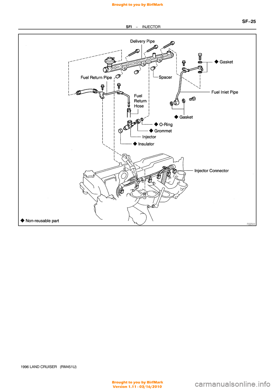
−
SFI INJECTOR
SF−25
1996 LAND CRUISER (RM451U)
Brought to you by BirfMark
Brought to you by BirfMark
Version 1.11 - 03/16/2010
Page 1212 of 1399
SF1EN−01
SF−26
−
SFI INJECTOR
1996 LAND CRUISER (RM451U)
REMOVAL
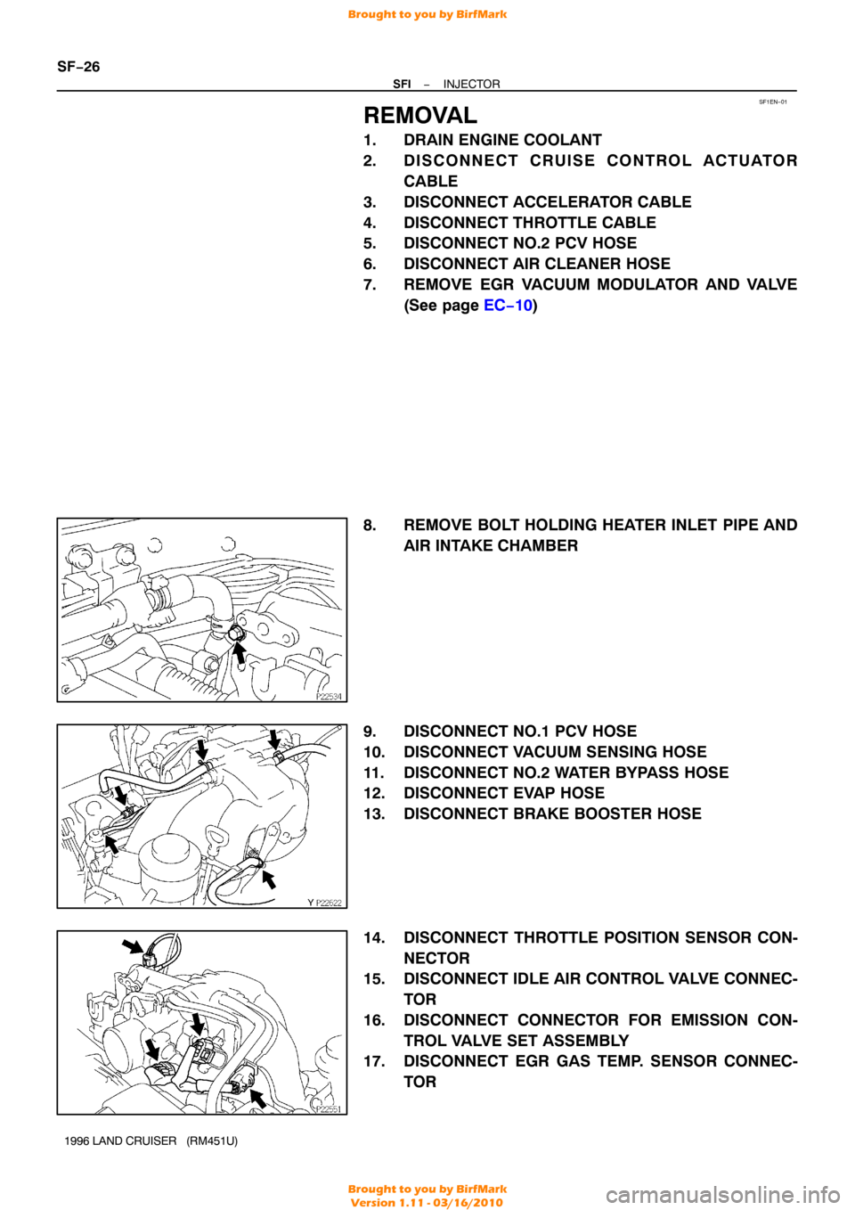
1. DRAIN ENGINE COOLANT
2. DISCONNECT CRUISE CONTROL ACTUATOR CABLE
3. DISCONNECT ACCELERATOR CABLE
4. DISCONNECT THROTTLE CABLE
5. DISCONNECT NO.2 PCV HOSE
6. DISCONNECT AIR CLEANER HOSE
7. REMOVE EGR VACUUM MODULATOR AND VALVE (See page EC−10 )
8. REMOVE BOLT HOLDING HEATER INLET PIPE AND AIR INTAKE CHAMBER
9. DISCONNECT NO.1 PCV HOSE
10. DISCONNECT VACUUM SENSING HOSE
11. DISCONNECT NO.2 WATER BYPASS HOSE
12. DISCONNECT EVAP HOSE
13. DISCONNECT BRAKE BOOSTER HOSE
14. DISCONNECT THROTTLE POSITION SENSOR CON- NECTOR
15. DISCONNECT IDLE AIR CONTROL VALVE CONNEC-
TOR
16. DISCONNECT CONNECTOR FOR EMISSION CON- TROL VALVE SET ASSEMBLY
17. DISCONNECT EGR GAS TEMP. SENSOR CONNEC-
TOR
Brought to you by BirfMark
Brought to you by BirfMark
Version 1.11 - 03/16/2010
Page 1213 of 1399
−
SFI INJECTOR
SF−27
1996 LAND CRUISER (RM451U)
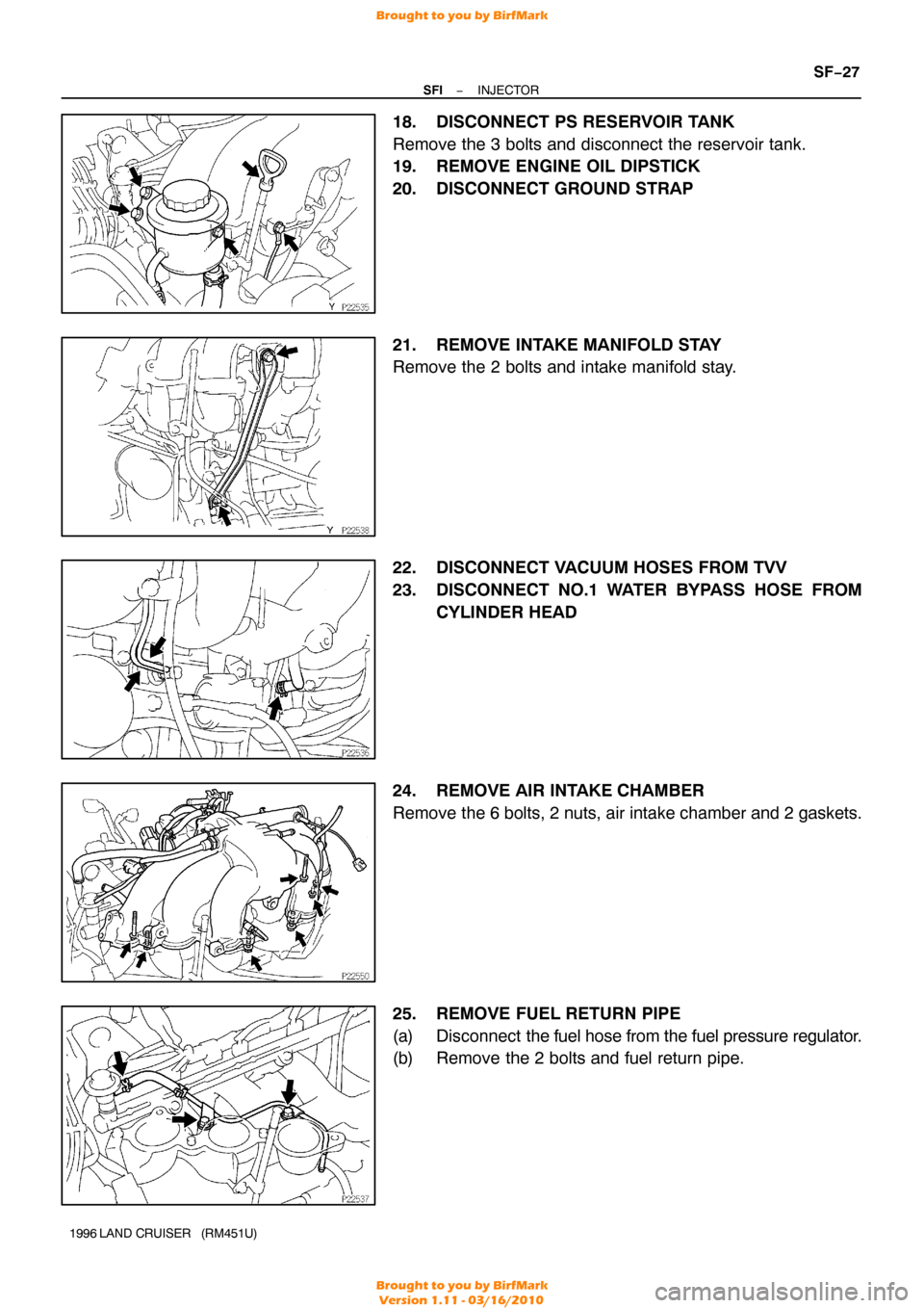
18. DISCONNECT PS RESERVOIR TANK
Remove the 3 bolts and disconnect the reservoir tank.
19. REMOVE ENGINE OIL DIPSTICK
20. DISCONNECT GROUND STRAP
21. REMOVE INTAKE MANIFOLD STAY
Remove the 2 bolts and intake manifold stay.
22. DISCONNECT VACUUM HOSES FROM TVV
23. DISCONNECT NO.1 WATER BYPASS HOSE FROM
CYLINDER HEAD
24. REMOVE AIR INTAKE CHAMBER
Remove the 6 bolts, 2 nuts, air intake chamber and 2 gaskets.
25. REMOVE FUEL RETURN PIPE
(a) Disconnect the fuel hose from the fuel pressure regulator.
(b) Remove the 2 bolts and fuel return pipe.
Brought to you by BirfMark
Brought to you by BirfMark
Version 1.11 - 03/16/2010
Page 1214 of 1399
SF−28
−
SFI INJECTOR
1996 LAND CRUISER (RM451U)
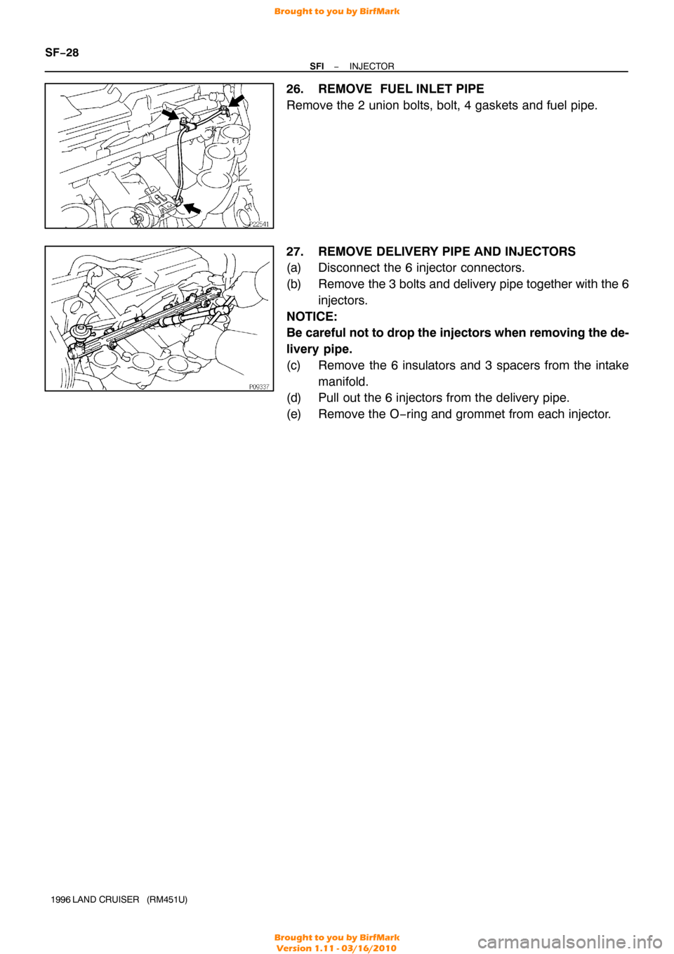
26. REMOVE FUEL INLET PIPE
Remove the 2 union bolts, bolt, 4 gaskets and fuel pipe.
27. REMOVE DELIVERY PIPE AND INJECTORS
(a) Disconnect the 6 injector connectors.
(b) Remove the 3 bolts and delivery pipe together with the 6
injectors.
NOTICE:
Be careful not to drop the injectors when removing the de-
livery pipe.
(c) Remove the 6 insulators and 3 spacers from the intake manifold.
(d) Pull out the 6 injectors from the delivery pipe.
(e) Remove the O−ring and grommet from each injector.
Brought to you by BirfMark
Brought to you by BirfMark
Version 1.11 - 03/16/2010
Page 1215 of 1399
SF1EO−03
−
SFI INJECTOR
SF−29
1996 LAND CRUISER (RM451U)
INSPECTION
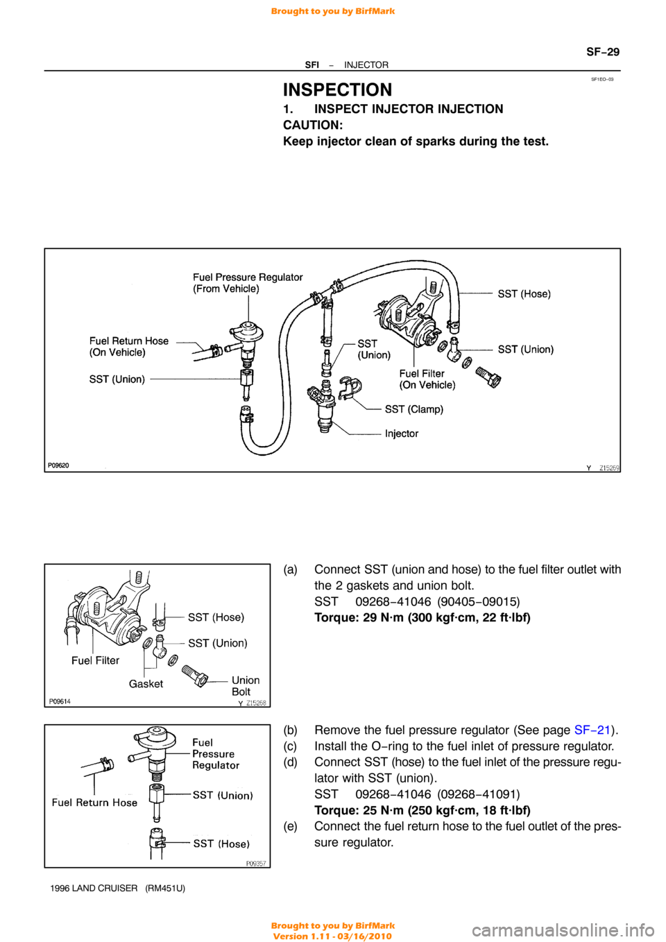
1. INSPECT INJECTOR INJECTION
CAUTION:
Keep injector clean of sparks during the test.
(a) Connect SST (union and hose) to the fuel filter outlet with
the 2 gaskets and union bolt.
SST 09268−41046 (90405 −09015)
Torque: 29 N·m (300 kgf·cm, 22 ft·lbf)
(b) Remove the fuel pressure regulator (See page SF−21).
(c) Install the O−ring to the fuel inlet of pressure regulator.
(d) Connect SST (hose) to the fuel inlet of the pressure regu-
lator with SST (union).
SST 09268−41046 (09268 −41091)
Torque: 25 N·m (250 kgf·cm, 18 ft·lbf)
(e) Connect the fuel return hose to the fuel outlet of the pres-
sure regulator.
Brought to you by BirfMark
Brought to you by BirfMark
Version 1.11 - 03/16/2010
Page 1216 of 1399
FI4848
FI4849
SF−30
−
SFI INJECTOR
1996 LAND CRUISER (RM451U)
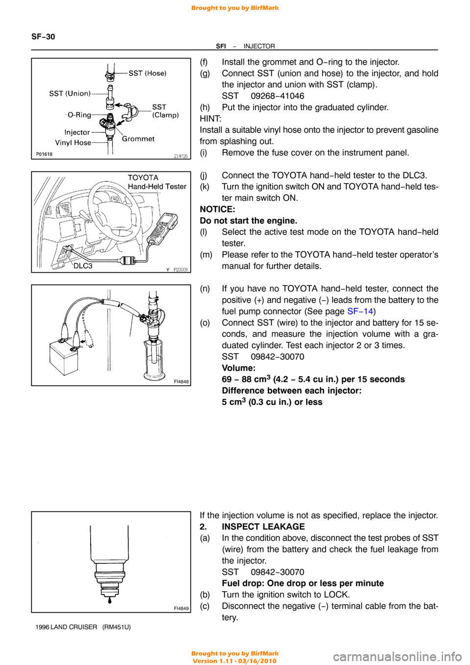
(f) Install the grommet and O−ring to the injector.
(g) Connect SST (union and hose) to the injector, and hold
the injector and union with SST (clamp).
SST 09268−41046
(h) Put the injector into the graduated cylinder.
HINT:
Install a suitable vinyl hose onto the injector to prevent gasoline
from splashing out.
(i) Remove the fuse cover on the instrument panel.
(j) Connect the TOYOTA hand−held tester to the DLC3.
(k) Turn the ignition switch ON and TOYOTA hand−held tes-
ter main switch ON.
NOTICE:
Do not start the engine.
(l) Select the active test mode on the TOYOTA hand −held
tester.
(m) Please refer to the TOYOTA hand −held tester operator’s
manual for further details.
(n) If you have no TOYOTA hand−held tester, connect the positive (+) and negative (−) leads from the battery to the
fuel pump connector (See page SF−14)
(o) Connect SST (wire) to the injector and battery for 15 se- conds, and measure the injection volume with a gra-
duated cylinder. Test each injector 2 or 3 times.
SST 09842−30070
Volume:
69 − 88 cm
3 (4.2 − 5.4 cu in.) per 15 seconds
Difference between each injector:
5 cm
3 (0.3 cu in.) or less
If the injection volume is not as specified, replace the injector.
2. INSPECT LEAKAGE
(a) In the condition above, disconnect the test probes of SST (wire) from the battery and check the fuel leakage from
the injector.
SST 09842−30070
Fuel drop: One drop or less per minute
(b) Turn the ignition switch to LOCK.
(c) Disconnect the negative ( −) terminal cable from the bat-
tery.
Brought to you by BirfMark
Brought to you by BirfMark
Version 1.11 - 03/16/2010
Page 1217 of 1399
−
SFI INJECTOR
SF−31
1996 LAND CRUISER (RM451U)
(d) Remove SST.
SST 09268−41045
(e) Reinstall the fuel pressure regulator to the delivery pipe
(See page SF−22 ).
(f) Disconnect the TOYOTA hand− held tester from the
DLC3.
(g) Reinstall the fuse cover on the instrument panel.
Brought to you by BirfMark
Brought to you by BirfMark
Version 1.11 - 03/16/2010
Page 1218 of 1399
SF1EP−01
FI6429
SF−32
−
SFI INJECTOR
1996 LAND CRUISER (RM451U)
INSTALLATION
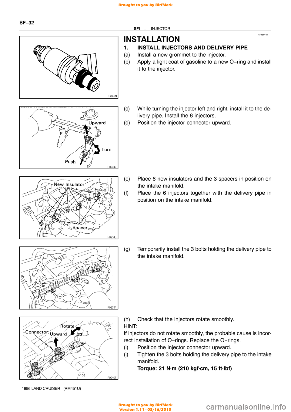
1. INSTALL INJECTORS AND DELIVERY PIPE
(a) Install a new grommet to the injector.
(b) Apply a light coat of gasoline to a new O −ring and install
it to the injector.
(c) While turning the injector left and right, install it to the de-
livery pipe. Install the 6 injectors.
(d) Position the injector connector upward.
(e) Place 6 new insulators and the 3 spacers in position on the intake manifold.
(f) Place the 6 injectors together with the delivery pipe in position on the intake manifold.
(g) Temporarily install the 3 bolts holding the delivery pipe to
the intake manifold.
(h) Check that the injectors rotate smoothly.
HINT:
If injectors do not rotate smoothly, the probable cause is incor-
rect installation of O−rings. Replace the O −rings.
(i) Position the injector connector upward.
(j) Tighten the 3 bolts holding the delivery pipe to the intake manifold.
Torque: 21 N·m (210 kgf·cm, 15 ft·lbf)
Brought to you by BirfMark
Brought to you by BirfMark
Version 1.11 - 03/16/2010
Page 1219 of 1399
−
SFI INJECTOR
SF−33
1996 LAND CRUISER (RM451U)
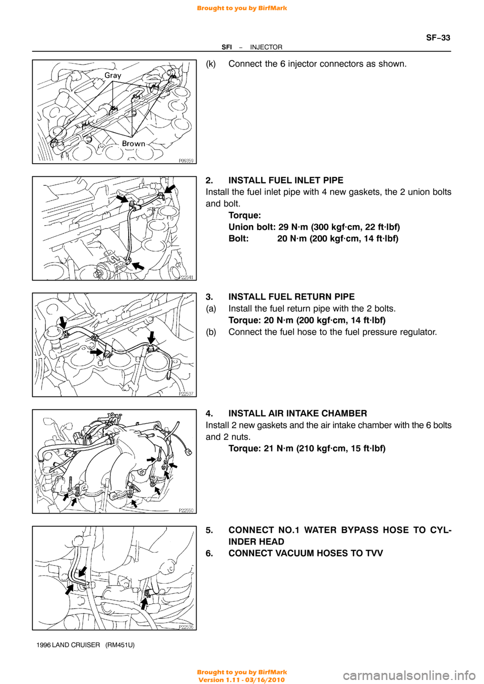
(k) Connect the 6 injector connectors as shown.
2. INSTALL FUEL INLET PIPE
Install the fuel inlet pipe with 4 new gaskets, the 2 union bolts
and bolt.
Torque:
Union bolt: 29 N·m (300 kgf·cm, 22 ft·lbf)
Bolt: 20 N·m (200 kgf·cm, 14 ft·lbf)
3. INSTALL FUEL RETURN PIPE
(a) Install the fuel return pipe with the 2 bolts. Torque: 20 N·m (200 kgf·cm, 14 ft·lbf)
(b) Connect the fuel hose to the fuel pressure regulator.
4. INSTALL AIR INTAKE CHAMBER
Install 2 new gaskets and the air intake chamber with the 6 bolts
and 2 nuts. Torque: 21 N·m (210 kgf·cm, 15 ft·lbf)
5. CONNECT NO.1 WATER BYPASS HOSE TO CYL- INDER HEAD
6. CONNECT VACUUM HOSES TO TVV
Brought to you by BirfMark
Brought to you by BirfMark
Version 1.11 - 03/16/2010
Page 1220 of 1399
SF−34
−
SFI INJECTOR
1996 LAND CRUISER (RM451U)
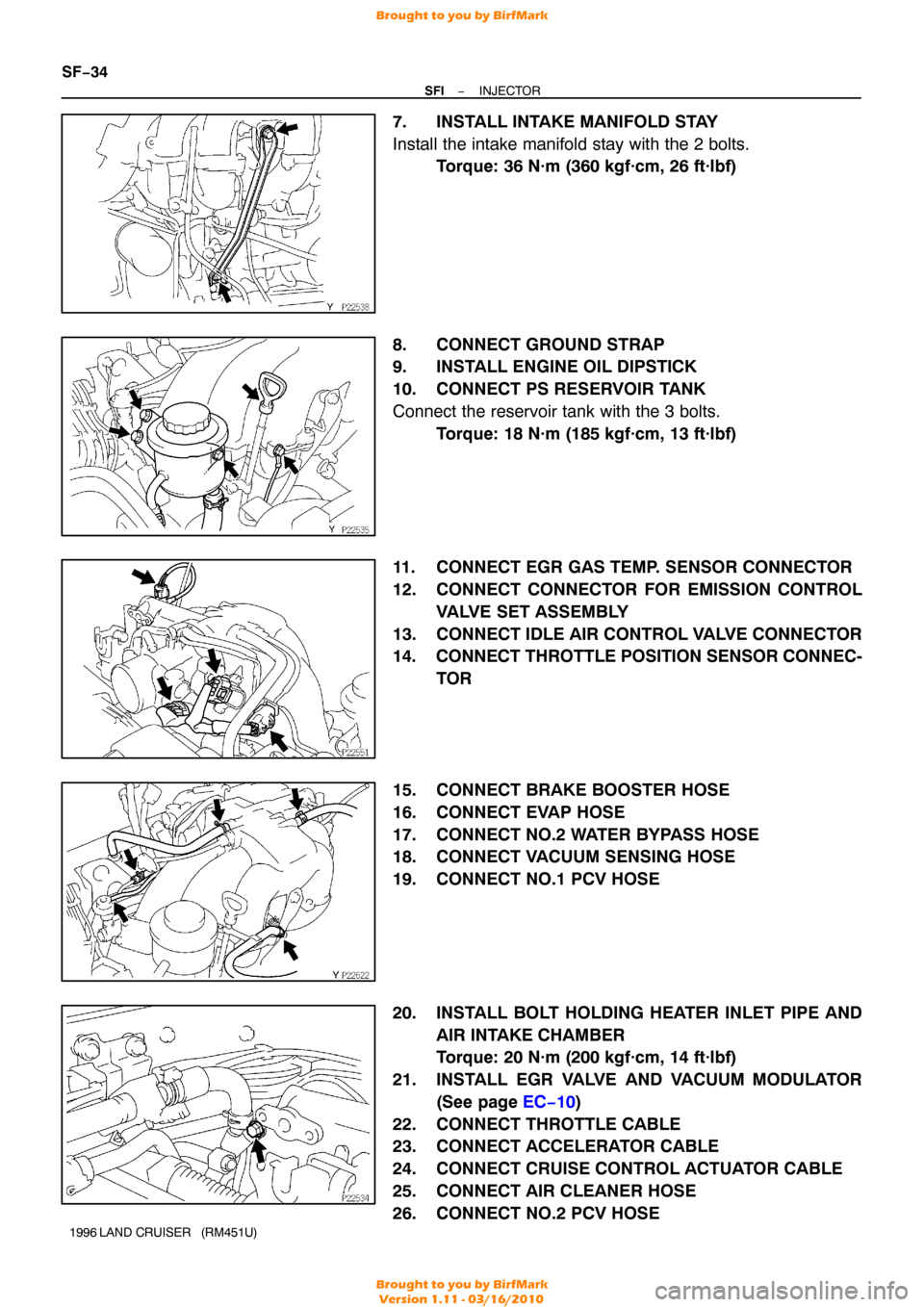
7. INSTALL INTAKE MANIFOLD STAY
Install the intake manifold stay with the 2 bolts.
Torque: 36 N·m (360 kgf·cm, 26 ft·lbf)
8. CONNECT GROUND STRAP
9. INSTALL ENGINE OIL DIPSTICK
10. CONNECT PS RESERVOIR TANK
Connect the reservoir tank with the 3 bolts. Torque: 18 N·m (185 kgf·cm, 13 ft·lbf)
11. CONNECT EGR GAS TEMP. SENSOR CONNECTOR
12. CONNECT CONNECTOR FOR EMISSION CONTROL VALVE SET ASSEMBLY
13. CONNECT IDLE AIR CONTROL VALVE CONNECTOR
14. CONNECT THROTTLE POSITION SENSOR CONNEC- TOR
15. CONNECT BRAKE BOOSTER HOSE
16. CONNECT EVAP HOSE
17. CONNECT NO.2 WATER BYPASS HOSE
18. CONNECT VACUUM SENSING HOSE
19. CONNECT NO.1 PCV HOSE
20. INSTALL BOLT HOLDING HEATER INLET PIPE AND AIR INTAKE CHAMBER
Torque: 20 N·m (200 kgf·cm, 14 ft·lbf)
21. INSTALL EGR VALVE AND VACUUM MODULATOR (See page EC−10 )
22. CONNECT THROTTLE CABLE
23. CONNECT ACCELERATOR CABLE
24. CONNECT CRUISE CONTROL ACTUATOR CABLE
25. CONNECT AIR CLEANER HOSE
26. CONNECT NO.2 PCV HOSE
Brought to you by BirfMark
Brought to you by BirfMark
Version 1.11 - 03/16/2010