valve clearance TOYOTA RAV4 1996 Service Repair Manual
[x] Cancel search | Manufacturer: TOYOTA, Model Year: 1996, Model line: RAV4, Model: TOYOTA RAV4 1996Pages: 1632, PDF Size: 41.64 MB
Page 134 of 1632
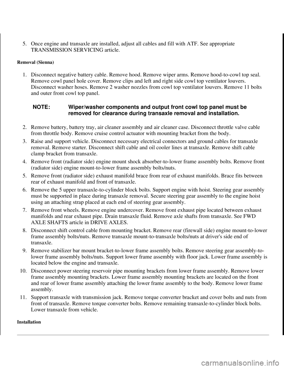
5. Once engine and transaxle are installed, adjust all cables and fill with ATF. See appropriate
TRANSMISSION SERVICING article.
Removal (Sienna)
1. Disconnect negative battery cable. Remove hood. Remove wiper arms. Remove hood-to-cowl top seal.
Remove cowl panel hole cover. Remove clips and left and right side cowl top ventilator louvers.
Disconnect washer hoses. Remove 2 washer nozzles from cowl top ventilator louvers. Remove 11 bolts
and outer front cowl top panel.
2. Remove battery, battery tray, air cleaner assembly and air cleaner case. Disconnect throttle valve cable
from throttle body. Remove cruise control actuator with mounting bracket from the body.
3. Raise and support vehicle. Disconnect necessary electrical connectors and ground cables for transaxle
removal. Remove starter. Disconnect shift cable and oil cooler lines at transaxle. Remove shift cable
clamp bracket from transaxle.
4. Remove front (radiator side) engine mount shock absorber-to-lower frame assembly bolts. Remove front
(radiator side) engine mount-to-lower frame assembly bolts/nuts.
5. Remove front (radiator side) exhaust manifold brace from rear of exhaust manifolds. Brace fits between
rear of exhaust manifold and front of transaxle.
6. Remove the 5 upper transaxle-to-cylinder block bolts. Support engine with hoist. Steering gear assembly
must be supported in place during transaxle removal. Secure steering gear assembly to the engine hoist
using an attaching strap placed at each end of steering gear assembly.
7. Remove front wheels. Remove engine undercover. Remove front exhaust pipe located between exhaust
manifolds and rear exhaust pipe. Drain transaxle fluid. Remove axle shafts from transaxle. See FWD
AXLE SHAFTS article in DRIVE AXLES.
8. Disconnect shift control cable from mounting bracket. Remove rear (firewall side) engine mount-to-lower
frame assembly bolts/nuts. Remove transaxle mount-to-transaxle bolts/nuts at driver's side end of
transaxle.
9. Remove stabilizer bar mount bracket-to-lower frame assembly bolts. Remove steering gear assembly-to-
lower frame assembly bolts/nuts. Support lower frame assembly with floor jack. Lower frame assembly is
located below the engine and transaxle.
10. Disconnect power steering reservoir pipe mounting brackets from lower frame assembly. Remove lower
frame assembly mounting brackets. Lower frame assembly mounting brackets are located on the front
and rear of lower frame assembly attaching the lower frame assembly to the body. Remove lower frame
assembly.
11. Support transaxle with transmission jack. Remove torque converter bracket and cover bolts and nuts from
front of transaxle. Remove torque converter bolts. Remove remaining transaxle-to-cylinder block bolts.
Lower transaxle from vehicle.
Installation
NOTE: Wiper/washer components and output front cowl top panel must be
removed for clearance during transaxle removal and installation.
1998 Toyota Avalon XLS
TRANSMISSION SERVICING - A/T 1997-98 TRANSMISSION SERVICING Toyota - Transmission Removal &
Installation
Helpmelearn
November-03-08 10:30:29 AMPage 22 © 2005 Mitchell Repair Information Company, LLC.
Page 177 of 1632
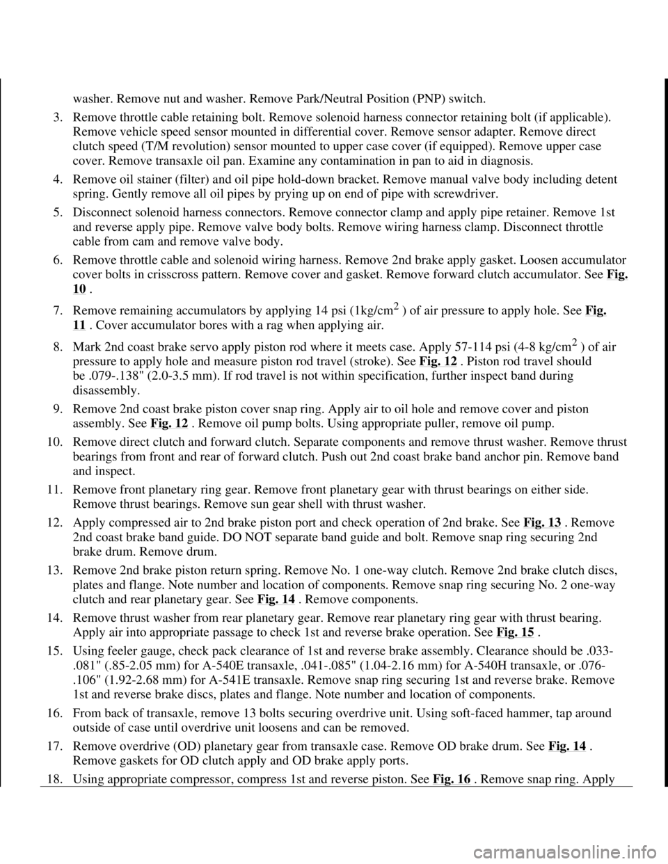
washer. Remove nut and washer. Remove Park/Neutral Position (PNP) switch.
3. Remove throttle cable retaining bolt. Remove solenoid harness connector retaining bolt (if applicable).
Remove vehicle speed sensor mounted in differential cover. Remove sensor adapter. Remove direct
clutch speed (T/M revolution) sensor mounted to upper case cover (if equipped). Remove upper case
cover. Remove transaxle oil pan. Examine any contamination in pan to aid in diagnosis.
4. Remove oil stainer (filter) and oil pipe hold-down bracket. Remove manual valve body including detent
spring. Gently remove all oil pipes by prying up on end of pipe with screwdriver.
5. Disconnect solenoid harness connectors. Remove connector clamp and apply pipe retainer. Remove 1st
and reverse apply pipe. Remove valve body bolts. Remove wiring harness clamp. Disconnect throttle
cable from cam and remove valve body.
6. Remove throttle cable and solenoid wiring harness. Remove 2nd brake apply gasket. Loosen accumulator
cover bolts in crisscross pattern. Remove cover and gasket. Remove forward clutch accumulator. See Fi
g.
10 .
7. Remove remaining accumulators by applying 14 psi (1kg/cm
2 ) of air pressure to apply hole. See Fig.
11 . Cover accumulator bores with a rag when applying air.
8. Mark 2nd coast brake servo apply piston rod where it meets case. Apply 57-114 psi (4-8 kg/cm
2 ) of air
pressure to apply hole and measure piston rod travel (stroke). See Fig. 12
. Piston rod travel should
be .079-.138" (2.0-3.5 mm). If rod travel is not within specification, further inspect band during
disassembly.
9. Remove 2nd coast brake piston cover snap ring. Apply air to oil hole and remove cover and piston
assembly. See Fig. 12
. Remove oil pump bolts. Using appropriate puller, remove oil pump.
10. Remove direct clutch and forward clutch. Separate components and remove thrust washer. Remove thrust
bearings from front and rear of forward clutch. Push out 2nd coast brake band anchor pin. Remove band
and inspect.
11. Remove front planetary ring gear. Remove front planetary gear with thrust bearings on either side.
Remove thrust bearings. Remove sun gear shell with thrust washer.
12. Apply compressed air to 2nd brake piston port and check operation of 2nd brake. See Fig. 13
. Remove
2nd coast brake band guide. DO NOT separate band guide and bolt. Remove snap ring securing 2nd
brake drum. Remove drum.
13. Remove 2nd brake piston return spring. Remove No. 1 one-way clutch. Remove 2nd brake clutch discs,
plates and flange. Note number and location of components. Remove snap ring securing No. 2 one-way
clutch and rear planetary gear. See Fig. 14
. Remove components.
14. Remove thrust washer from rear planetary gear. Remove rear planetary ring gear with thrust bearing.
Apply air into appropriate passage to check 1st and reverse brake operation. See Fig. 15
.
15. Using feeler gauge, check pack clearance of 1st and reverse brake assembly. Clearance should be .033-
.081" (.85-2.05 mm) for A-540E transaxle, .041-.085" (1.04-2.16 mm) for A-540H transaxle, or .076-
.106" (1.92-2.68 mm) for A-541E transaxle. Remove snap ring securing 1st and reverse brake. Remove
1st and reverse brake discs, plates and flange. Note number and location of components.
16. From back of transaxle, remove 13 bolts securing overdrive unit. Using soft-faced hammer, tap around
outside of case until overdrive unit loosens and can be removed.
17. Remove overdrive (OD) planetary gear from transaxle case. Remove OD brake drum. See Fig. 14
.
Remove gaskets for OD clutch apply and OD brake apply ports.
18. Usin
g appropriate compressor, compress 1st and reverse piston. See Fig. 16 . Remove snap ring. Apply
1998 Toyota Avalon XLS
1997-99 AUTOMATIC TRANSMISSIONS Toyota A-540E, A-540H & A-541E Overhaul
Helpmelearn
November-03-08 10:28:17 AMPage 23 © 2005 Mitchell Repair Information Company, LLC.
Page 255 of 1632
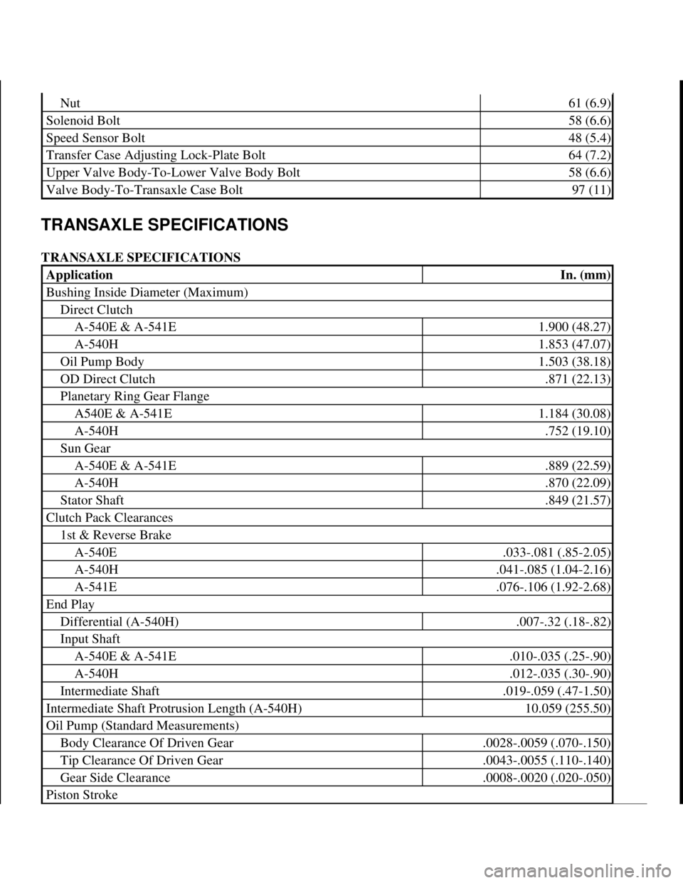
TRANSAXLE SPECIFICATIONS
TRANSAXLE SPECIFICATIONS
Nut61 (6.9)
Solenoid Bolt58 (6.6)
Speed Sensor Bolt48 (5.4)
Transfer Case Adjusting Lock-Plate Bolt64 (7.2)
Upper Valve Body-To-Lower Valve Body Bolt58 (6.6)
Valve Body-To-Transaxle Case Bolt97 (11)
ApplicationIn. (mm)
Bushing Inside Diameter (Maximum)
Direct Clutch
A-540E & A-541E1.900 (48.27)
A-540H1.853 (47.07)
Oil Pump Body1.503 (38.18)
OD Direct Clutch.871 (22.13)
Planetary Ring Gear Flange
A540E & A-541E1.184 (30.08)
A-540H.752 (19.10)
Sun Gear
A-540E & A-541E.889 (22.59)
A-540H.870 (22.09)
Stator Shaft.849 (21.57)
Clutch Pack Clearances
1st & Reverse Brake
A-540E.033-.081 (.85-2.05)
A-540H.041-.085 (1.04-2.16)
A-541E.076-.106 (1.92-2.68)
End Play
Differential (A-540H).007-.32 (.18-.82)
Input Shaft
A-540E & A-541E.010-.035 (.25-.90)
A-540H.012-.035 (.30-.90)
Intermediate Shaft.019-.059 (.47-1.50)
Intermediate Shaft Protrusion Length (A-540H)10.059 (255.50)
Oil Pump (Standard Measurements)
Body Clearance Of Driven Gear.0028-.0059 (.070-.150)
Tip Clearance Of Driven Gear.0043-.0055 (.110-.140)
Gear Side Clearance.0008-.0020 (.020-.050)
Piston Stroke
1998 Toyota Avalon XLS
1997-99 AUTOMATIC TRANSMISSIONS Toyota A-540E, A-540H & A-541E Overhaul
Helpmelearn
November-03-08 10:28:20 AMPage 101 © 2005 Mitchell Repair Information Company, LLC.
Page 370 of 1632
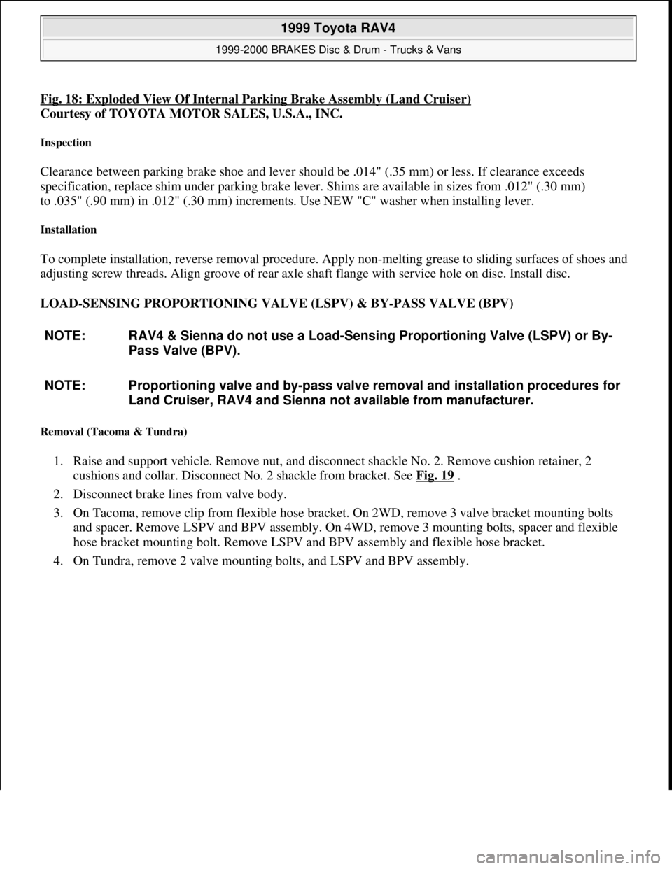
Fig. 18: Exploded View Of Internal Parking Brake Assembly (Land Cruiser)
Courtesy of TOYOTA MOTOR SALES, U.S.A., INC.
Inspection
Clearance between parking brake shoe and lever should be .014" (.35 mm) or less. If clearance exceeds
specification, replace shim under parking brake lever. Shims are available in sizes from .012" (.30 mm)
to .035" (.90 mm) in .012" (.30 mm) increments. Use NEW "C" washer when installing lever.
Installation
To complete installation, reverse removal procedure. Apply non-melting grease to sliding surfaces of shoes and
adjusting screw threads. Align groove of rear axle shaft flange with service hole on disc. Install disc.
LOAD-SENSING PROPORTIONING VALVE (LSPV) & BY-PASS VALVE (BPV)
Removal (Tacoma & Tundra)
1. Raise and support vehicle. Remove nut, and disconnect shackle No. 2. Remove cushion retainer, 2
cushions and collar. Disconnect No. 2 shackle from bracket. See Fig. 19
.
2. Disconnect brake lines from valve body.
3. On Tacoma, remove clip from flexible hose bracket. On 2WD, remove 3 valve bracket mounting bolts
and spacer. Remove LSPV and BPV assembly. On 4WD, remove 3 mounting bolts, spacer and flexible
hose bracket mounting bolt. Remove LSPV and BPV assembly and flexible hose bracket.
4. On Tundra, remove 2 valve mountin
g bolts, and LSPV and BPV assembly. NOTE: RAV4 & Sienna do not use a Load-Sensing Proportioning Valve (LSPV) or By-
Pass Valve (BPV).
NOTE: Proportioning valve and by-pass valve removal and installation procedures for
Land Cruiser, RAV4 and Sienna not available from manufacturer.
1999 Toyota RAV4
1999-2000 BRAKES Disc & Drum - Trucks & Vans
Microsoft
Sunday, November 22, 2009 10:07:28 AMPage 31 © 2005 Mitchell Repair Information Company, LLC.
Page 685 of 1632
VALVE CLEARANCE ADJUSTMENT
1. Disconnect power steering fluid reservoir, PCV hoses, cable brackets and control cables for access to
valve cover. Disconnect spark plug wires from spark plugs.
2. Disconnect engine wiring harness protector at rear of timing belt cover for access to valve cover. When
disconnecting engine wiring harness protector, remove bolt on intake manifold side of engine first, and
then bolt on exhaust manifold side of engine.
3. Remove nuts, grommets, valve cover and gasket. Note location of grommets for reassembly reference, as
grommets must be installed in original location.
4. Rotate crankshaft clockwise, as viewed from timing belt end of engine, so cylinder No. 1 is at TDC on
compression stroke, and timing mark on crankshaft pulley aligns with "0" mark on timing belt cover.
Cylinder No. 1 is front cylinder at timing belt end of engine.
5. Ensure valve lifters are loose on cylinder No. 1 and tight on cylinder No. 4. If conditions are not as
described, rotate crankshaft clockwise one complete revolution (360 degrees).
6. With cylinder No. 1 at TDC on compression stroke, check valve clearance on specified valves. Perform
STEP 1 in illustration. See Fig. 2
. Using feeler gauge, measure and record valve clearance between valve
lifter and camshaft. NOTE: Adjust valve clearance with engine cold.
1999 Toyota RAV4
1999-2000 ENGINES 2.0L 4-Cylinder
Microsoft
Sunday, November 22, 2009 10:22:26 AMPage 2 © 2005 Mitchell Repair Information Company, LLC.
Page 686 of 1632
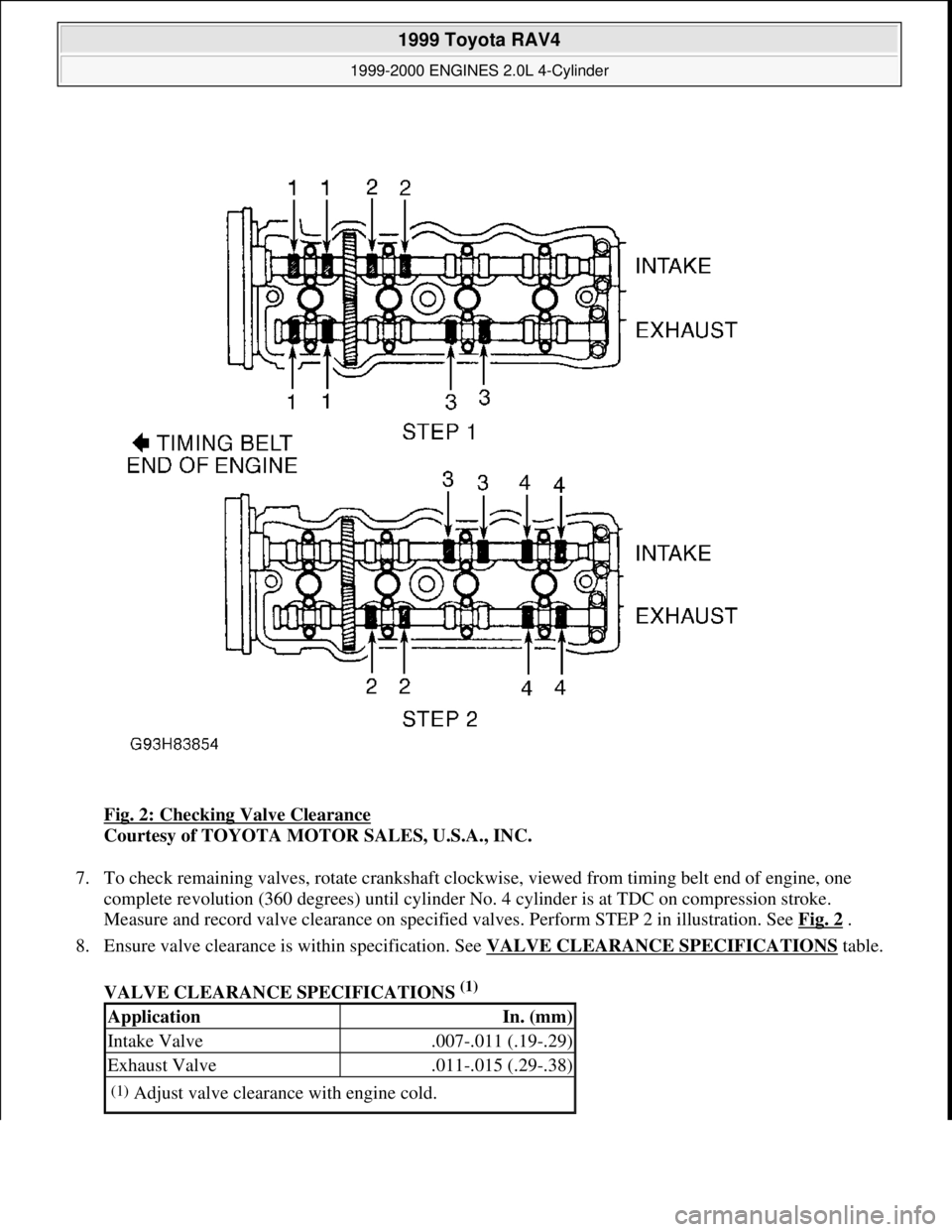
Fig. 2: Checking Valve Clearance
Courtesy of TOYOTA MOTOR SALES, U.S.A., INC.
7. To check remaining valves, rotate crankshaft clockwise, viewed from timing belt end of engine, one
complete revolution (360 degrees) until cylinder No. 4 cylinder is at TDC on compression stroke.
Measure and record valve clearance on specified valves. Perform STEP 2 in illustration. See Fig. 2
.
8. Ensure valve clearance is within specification. See VALVE CLEARANCE SPECIFICATIONS
table.
VALVE CLEARANCE SPECIFICATIONS
(1)
ApplicationIn. (mm)
Intake Valve.007-.011 (.19-.29)
Exhaust Valve.011-.015 (.29-.38)
(1)Adjust valve clearance with engine cold.
1999 Toyota RAV4
1999-2000 ENGINES 2.0L 4-Cylinder
Microsoft
Sunday, November 22, 2009 10:22:26 AMPage 3 © 2005 Mitchell Repair Information Company, LLC.
Page 687 of 1632
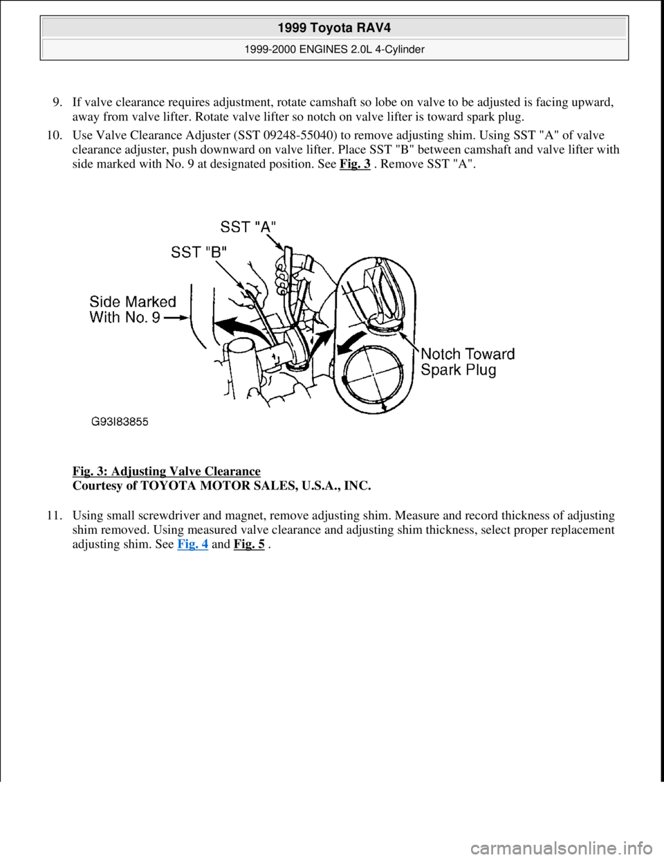
9. If valve clearance requires adjustment, rotate camshaft so lobe on valve to be adjusted is facing upward,
away from valve lifter. Rotate valve lifter so notch on valve lifter is toward spark plug.
10. Use Valve Clearance Adjuster (SST 09248-55040) to remove adjusting shim. Using SST "A" of valve
clearance adjuster, push downward on valve lifter. Place SST "B" between camshaft and valve lifter with
side marked with No. 9 at designated position. See Fig. 3
. Remove SST "A".
Fig. 3: Adjusting Valve Clearance
Courtesy of TOYOTA MOTOR SALES, U.S.A., INC.
11. Using small screwdriver and magnet, remove adjusting shim. Measure and record thickness of adjusting
shim removed. Using measured valve clearance and adjusting shim thickness, select proper replacement
adjusting shim. See Fig. 4
and Fig. 5 .
1999 Toyota RAV4
1999-2000 ENGINES 2.0L 4-Cylinder
Microsoft
Sunday, November 22, 2009 10:22:26 AMPage 4 © 2005 Mitchell Repair Information Company, LLC.
Page 691 of 1632
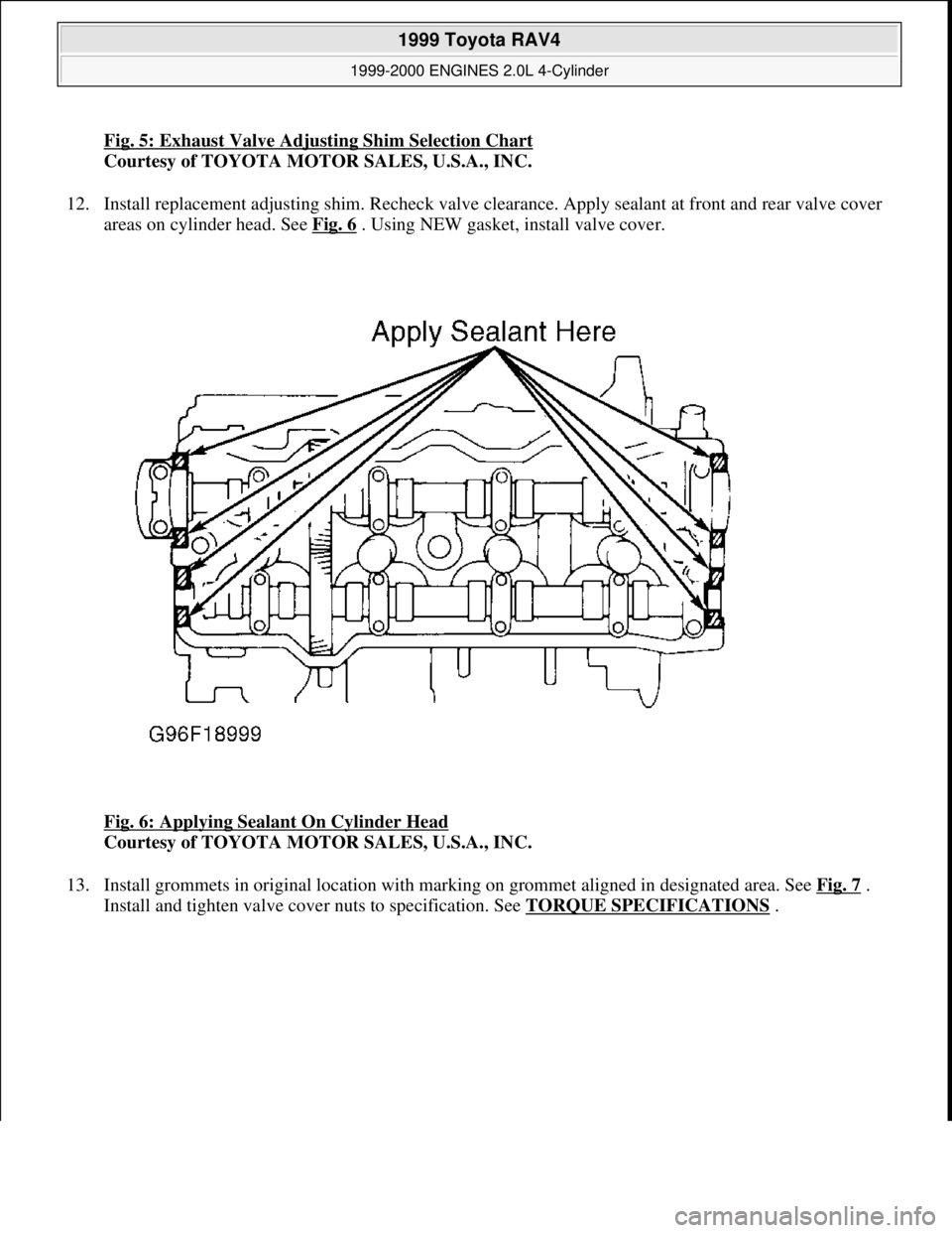
Fig. 5: Exhaust Valve Adjusting Shim Selection Chart
Courtesy of TOYOTA MOTOR SALES, U.S.A., INC.
12. Install replacement adjusting shim. Recheck valve clearance. Apply sealant at front and rear valve cover
areas on cylinder head. See Fig. 6
. Using NEW gasket, install valve cover.
Fig. 6: Applying Sealant On Cylinder Head
Courtesy of TOYOTA MOTOR SALES, U.S.A., INC.
13. Install grommets in original location with marking on grommet aligned in designated area. See Fig. 7
.
Install and ti
ghten valve cover nuts to specification. See TORQUE SPECIFICATIONS.
1999 Toyota RAV4
1999-2000 ENGINES 2.0L 4-Cylinder
Microsoft
Sunday, November 22, 2009 10:22:26 AMPage 8 © 2005 Mitchell Repair Information Company, LLC.
Page 704 of 1632
Inspection
1. Inspect cylinder head warpage at cylinder block, exhaust manifold and intake manifold surfaces. Replace
cylinder head if warpage exceeds specification. See CYLINDER HEAD
table under ENGINE
SPECIFICATIONS.
2. Inspect cylinder block deck surface for warpage. Replace cylinder block if deck surface warpage exceeds
specification. See CYLINDER BLOCK
table under ENGINE SPECIFICATIONS.
3. Inspect intake and exhaust manifold machined surfaces for warpage. Replace component if warpage
exceeds .0118" (.300 mm). Inspect camshaft and components. See CAMSHAFT
.
4. Measure valve lifter diameter and bore diameter. Ensure oil clearance is within specification. Replace
components if not within specification. See VALVE LIFTERS
table under ENGINE
SPECIFICATIONS.
Installation
1. Apply adhesive to 2 or 3 threads of oil pressure switch, and install switch. Install NEW insulator at
bottom of fuel injector and NEW grommet on top of fuel injector. Coat NEW "O" rings with gasoline and
install on fuel injector.
2. Install 2 spacers on cylinder head. Install fuel injectors on cylinder head. Install fuel delivery pipe on fuel
injectors. Using twisting motion, push fuel injectors into fuel delivery pipe.
3. Install and slightly tighten fuel delivery pipe-to-cylinder head bolts. Ensure all fuel injectors rotate
smoothly. If fuel injector fails to rotate smoothly, check for improperly installed or damaged "O" rings.
4. Position electrical connector on fuel injector facing toward top of engine. Tighten fuel delivery pipe-to-
cylinder head bolts to specification. See TORQUE SPECIFICATIONS
.
5. Using NEW gasket, install intake manifold. Install and tighten bolts/nuts to specification. See TORQUE
SPECIFICATIONS . Install air tube on side of intake manifold.
6. Install adjusting shims and valve lifters in original location on cylinder head (if removed). Ensure valve
lifters rotate smoothly in cylinder head.
7. Install NEW gasket for cylinder head on cylinder block. Ensure all holes in gasket align with holes in
cylinder block.
8. Install cylinder head. Coat threads and bolt-to-cylinder contact surfaces on cylinder head bolts with
engine oil. Install and tighten cylinder head bolts in several steps, to specification in sequence. See Fig.
15 . See TORQUE SPECIFICATIONS .
9. If removed, install spark plug tubes. Install camshafts using proper procedure. See CAMSHAFT
. Install
No. 3 timing belt cover. Install and tighten bolts to specification. See TORQUE SPECIFICATIONS
.
10. To install remaining components, reverse removal procedure. If camshaft or cylinder head components
are serviced, adjust valve clearance. See VALVE CLEARANCE ADJUSTMENT
under
ADJUSTMENTS.
11. Before installing gasket and valve cover, apply sealant at front and rear valve cover areas on cylinder
head. See Fig. 6
. Using NEW gasket, install valve cover.
12. Install grommets in original location with marking on grommet aligned in designated area. See Fig. 7
.
Install and tighten valve cover nuts to specification. See TORQUE SPECIFICATIONS
.
13. Install VSV for EGR. Connect ground cable to intake manifold with bolt. Connect knock sensor
connector. Connect power steerin
g idle-up air hoses to air tube. On A/T models, connect A/T throttle
1999 Toyota RAV4
1999-2000 ENGINES 2.0L 4-Cylinder
Microsoft
Sunday, November 22, 2009 10:22:26 AMPage 21 © 2005 Mitchell Repair Information Company, LLC.
Page 711 of 1632
VALVE LIFTER
Removal
Remove camshaft. See CAMSHAFT . Note location of adjusting shims and valve lifters for reassembly
reference. Remove adjusting shims and valve lifters from cylinder head.
Inspection
Inspect components for damage. Measure valve lifter diameter and bore diameter. Ensure oil clearance is within
specification. Replace components if not within specification. See VALVE LIFTERS
table under ENGINE
SPECIFICATIONS.
Installation
To install, reverse removal procedure. Ensure components are installed in original location and valve lifters
rotate smoothly in cylinder head. If camshaft, adjusting shims or valve lifters are replaced, check valve
clearance. See VALVE CLEARANCE ADJUSTMENT
under ADJUSTMENTS.
CAMSHAFT
Removal (Exhaust Side)
1. Remove timing belt and camshaft sprocket. See TIMING BELT . Remove No. 3 timing belt cover. See
Fig. 14
.
2. Disconnect power steering fluid reservoir, PCV hoses, cable brackets and control cables for access to
valve cover. Disconnect spark plug wires from spark plugs. Remove nuts, grommets, valve cover and
gasket. Note location of grommets for reassembly reference, as grommets must be installed in original
location.
3. For servicing of exhaust camshaft, rotate intake camshaft so knock pin is 10-45 degrees from vertical
position. See Fig. 19
. This aids in exhaust camshaft removal by using camshaft lobes on cylinders No. 2
and 4 to push on valve lifters. CAUTION: Camshafts must be properly positioned to lift camshaft straight from
cylinder head to prevent damage to cylinder head and camshaft. DO
NOT pry or force camshafts from cylinder head or component
damage will result.
1999 Toyota RAV4
1999-2000 ENGINES 2.0L 4-Cylinder
Microsoft
Sunday, November 22, 2009 10:22:26 AMPage 28 © 2005 Mitchell Repair Information Company, LLC.