cruise control TOYOTA RAV4 1996 Service User Guide
[x] Cancel search | Manufacturer: TOYOTA, Model Year: 1996, Model line: RAV4, Model: TOYOTA RAV4 1996Pages: 1632, PDF Size: 41.64 MB
Page 274 of 1632
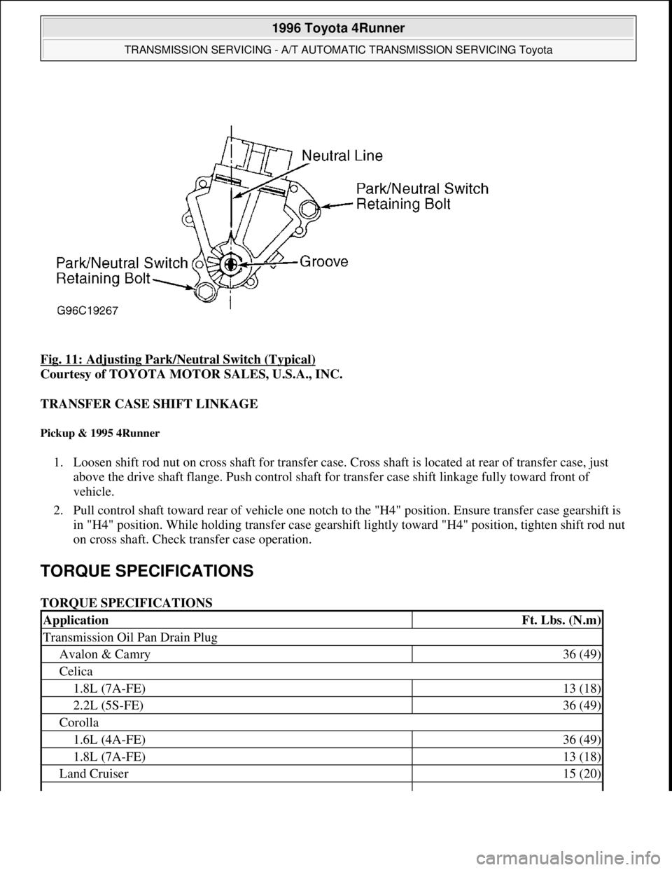
Fig. 11: Adjusting Park/Neutral Switch (Typical)
Courtesy of TOYOTA MOTOR SALES, U.S.A., INC.
TRANSFER CASE SHIFT LINKAGE
Pickup & 1995 4Runner
1. Loosen shift rod nut on cross shaft for transfer case. Cross shaft is located at rear of transfer case, just
above the drive shaft flange. Push control shaft for transfer case shift linkage fully toward front of
vehicle.
2. Pull control shaft toward rear of vehicle one notch to the "H4" position. Ensure transfer case gearshift is
in "H4" position. While holding transfer case gearshift lightly toward "H4" position, tighten shift rod nut
on cross shaft. Check transfer case operation.
TORQUE SPECIFICATIONS
TORQUE SPECIFICATIONS
ApplicationFt. Lbs. (N.m)
Transmission Oil Pan Drain Plug
Avalon & Camry36 (49)
Celica
1.8L (7A-FE)13 (18)
2.2L (5S-FE)36 (49)
Corolla
1.6L (4A-FE)36 (49)
1.8L (7A-FE)13 (18)
Land Cruiser15 (20)
1996 Toyota 4Runner
TRANSMISSION SERVICING - A/T AUTOMATIC TRANSMISSION SERVICING Toyota
Microsoft
Tuesday, August 18, 2009 7:18:46 PMPage 18 © 2005 Mitchell Repair Information Company, LLC.
Page 281 of 1632
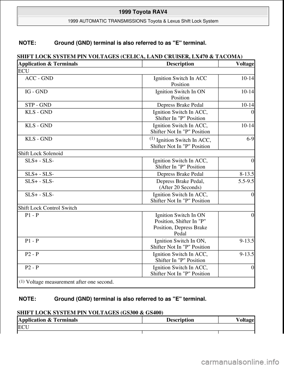
SHIFT LOCK SYSTEM PIN VOLTAGES (CELICA, LAND CRUISER, LX470 & TACOMA)
SHIFT LOCK SYSTEM PIN VOLTAGES (GS300 & GS400) NOTE: Ground (GND) terminal is also referred to as "E" terminal.
Application & TerminalsDescriptionVoltage
ECU
ACC - GNDIgnition Switch In ACC
Position10-14
IG - GNDIgnition Switch In ON
Position10-14
STP - GNDDepress Brake Pedal10-14
KLS - GNDIgnition Switch In ACC,
Shifter In "P" Position0
KLS - GNDIgnition Switch In ACC,
Shifter Not In "P" Position10-14
KLS - GND(1) Ignition Switch In ACC,
Shifter Not In "P" Position6-9
Shift Lock Solenoid
SLS+ - SLS-Ignition Switch In ACC,
Shifter In "P" Position0
SLS+ - SLS-Depress Brake Pedal8-13.5
SLS+ - SLS-Depress Brake Pedal,
(After 20 Seconds)5.5-9.5
SLS+ - SLS-Ignition Switch In ACC,
Shifter Not In "P" Position0
Shift Lock Control Switch
P1 - PIgnition Switch In ON
Position, Shifter In "P"
Position, Depress Brake
Pedal0
P1 - PIgnition Switch In ON,
Shifter Not In "P" Position9-13.5
P2 - PIgnition Switch In ACC,
Shifter In "P" Position9-13.5
P2 - PIgnition Switch In ACC,
Shifter Not In "P" Position0
(1)Voltage measurement after one second.
NOTE: Ground (GND) terminal is also referred to as "E" terminal.
Application & TerminalsDescriptionVoltage
ECU
1999 Toyota RAV4
1999 AUTOMATIC TRANSMISSIONS Toyota & Lexus Shift Lock System
Microsoft
Sunday, November 22, 2009 10:46:00 AMPage 4 © 2005 Mitchell Repair Information Company, LLC.
Page 286 of 1632
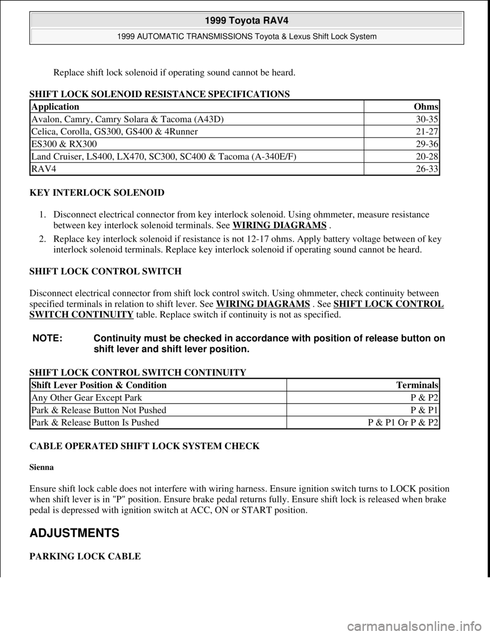
Replace shift lock solenoid if operating sound cannot be heard.
SHIFT LOCK SOLENOID RESISTANCE SPECIFICATIONS
KEY INTERLOCK SOLENOID
1. Disconnect electrical connector from key interlock solenoid. Using ohmmeter, measure resistance
between key interlock solenoid terminals. See WIRING DIAGRAMS
.
2. Replace key interlock solenoid if resistance is not 12-17 ohms. Apply battery voltage between of key
interlock solenoid terminals. Replace key interlock solenoid if operating sound cannot be heard.
SHIFT LOCK CONTROL SWITCH
Disconnect electrical connector from shift lock control switch. Using ohmmeter, check continuity between
specified terminals in relation to shift lever. See WIRING DIAGRAMS
. See SHIFT LOCK CONTROL
SWITCH CONTINUITY table. Replace switch if continuity is not as specified.
SHIFT LOCK CONTROL SWITCH CONTINUITY
CABLE OPERATED SHIFT LOCK SYSTEM CHECK
Sienna
Ensure shift lock cable does not interfere with wiring harness. Ensure ignition switch turns to LOCK position
when shift lever is in "P" position. Ensure brake pedal returns fully. Ensure shift lock is released when brake
pedal is depressed with ignition switch at ACC, ON or START position.
ADJUSTMENTS
PARKING LOCK CABLE
ApplicationOhms
Avalon, Camry, Camry Solara & Tacoma (A43D)30-35
Celica, Corolla, GS300, GS400 & 4Runner21-27
ES300 & RX30029-36
Land Cruiser, LS400, LX470, SC300, SC400 & Tacoma (A-340E/F)20-28
RAV426-33
NOTE: Continuity must be checked in accordance with position of release button on
shift lever and shift lever position.
Shift Lever Position & ConditionTerminals
Any Other Gear Except ParkP & P2
Park & Release Button Not PushedP & P1
Park & Release Button Is PushedP & P1 Or P & P2
1999 Toyota RAV4
1999 AUTOMATIC TRANSMISSIONS Toyota & Lexus Shift Lock System
Microsoft
Sunday, November 22, 2009 10:46:00 AMPage 9 © 2005 Mitchell Repair Information Company, LLC.
Page 340 of 1632
1999-2000 BRAKES
Disc & Drum - Trucks & Vans
DESCRIPTION & OPERATION
Hydraulic brake system uses a tandem master cylinder with a vacuum power assist servo. All models (except
Land Cruiser) are equipped with front disc brakes and rear drum brakes standard. Rear disc brakes are standard
on Land Cruiser models.
A Load-Sensing Proportioning Valve (LSVP) is used to regulate brake pressure between front and rear brakes.
Rear brakes on all models are self-adjusting.
Parking brake lever mechanically activates rear brakes. On models with rear drum brakes, a cable applies rear
shoes. On models with rear disc brakes, parking brake is a drum brake internal to rear disc assembly.
BLEEDING BRAKE SYSTEM
BLEEDING PROCEDURES
1. If master cylinder is rebuilt or reservoir is empty, bleed master cylinder first. Bleed wheels in sequence.
Start on wheel with longest hydraulic line, and work toward wheel with shortest hydraulic line.
2. Raise and support vehicle. Ensure brake fluid reservoir is at least half full during bleeding procedure.
Connect one end of transparent vinyl tube to bleeder screw. Submerge other end of tube in a container
half filled with clean brake fluid.
3. Have an assistant depress brake pedal several times and hold in depressed position. Loosen bleeder screw,
and drain fluid into container. Tighten bleeder screw. WARNING:For warnings and procedures regarding vehicles equipped with Anti-Lock
Brake Systems (ABS), see appropriate ANTI-LOCK article.
NOTE: For disc brake coverage on Lexus LX470, see Land Cruiser information in this
article. The 1999 Land Cruiser and Lexus LX470 information is the same. The
2000 Land Cruiser information for models equipped with traction control ABS is
the same on 2000 LX470. Models with traction control ABS do not use a Load-
Sensing Proportioning Valve (lspv) and By-Pass Valve (BPV).
CAUTION: DO NOT allow reservoir to run dry during brake bleeding procedure. Use
only clean brake fluid. Ensure no dirt or other foreign matter contaminates
brake fluid. DO NOT mix different types of brake fluid, as they may not be
compatible. DO NOT spill brake fluid on vehicle, as it may damage paint. If
brake fluid contacts paint, immediately wash with water.
NOTE: Ensure brake pedal remains depressed until bleeder screw is tightened.
1999 Toyota RAV4
1999-2000 BRAKES Disc & Drum - Trucks & Vans
1999 Toyota RAV4
1999-2000 BRAKES Disc & Drum - Trucks & Vans
Microsoft
Sunday, November 22, 2009 10:07:28 AMPage 1 © 2005 Mitchell Repair Information Company, LLC.
Microsoft
Sunday, November 22, 2009 10:07:32 AMPage 1 © 2005 Mitchell Repair Information Company, LLC.
Page 349 of 1632

PROPORTIONING VALVE & BY-PASS VALVE
Land Cruiser (Models Without Traction Control ABS)
1. Turn ignition off. Depress brake pedal at least 40 times. Install proportioning valve gauge to front brake
caliper brake line connection and to rear brake caliper brake line connection. Bleed air from gauges and
lines.
2. Turn ignition to ON position and wait until pump motor has stopped. Raise front brake caliper pressure
and check rear brake caliper pressure by depressing brake pedal and checking fluid pressure on gauges.
3. If rear brake caliper pressure is incorrect, replace hydraulic brake booster. See HYDRAULIC BRAKE
BOOSTER under REMOVAL & INSTALLATION.
PROPORTIONING VALVE & BY-PASS VALVE PRESSURE SPECIFICATIONS (LAND CRUISER)
REMOVAL & INSTALLATION
FRONT DISC BRAKE PADS
Removal & Installation (Land Cruiser)
Raise and support vehicle. Remove front wheel. Remove clip, 2 pins, 2 pad retainer clips, pads, anti-squeal
shims and pad retainers. See Fig. 5
. Remove enough brake fluid from master cylinder so overflow will not
occur as piston is seated. Seat pistons using a hammer handle or equivalent. Slide NEW pads and anti-rattle
shims into caliper. Check reservoir fluid level. To install, reverse removal procedure. Tighten lower caliper bolt
to specification. See TORQUE SPECIFICATIONS
.
Sienna
Low Pressure Reading427 (30)427 (30)
High Pressure Reading1138 (80)711 (50)
Front Brake Caliper Pressure - psi (kg/cm2)Rear Brake Caliper Pressure - psi (kg/cm2)
327 (23)356 (25)
640 (45)484-540 (34-38)
1138 (80)754 (53)
NOTE: Location and number of anti-rattle springs, anti-squeal shims, pad support and
guide plates vary between models. Note component locations during removal
process for reassembly reference. Tacoma, Tundra and 4Runner with 4WD use
dual-piston calipers; other models use single-piston calipers.
NOTE: Pushing piston into caliper bore will force fluid back into master cylinder
reservoir. Remove reservoir cap when compressing caliper piston.
1999 Toyota RAV4
1999-2000 BRAKES Disc & Drum - Trucks & Vans
Microsoft
Sunday, November 22, 2009 10:07:28 AMPage 10 © 2005 Mitchell Repair Information Company, LLC.
Page 365 of 1632
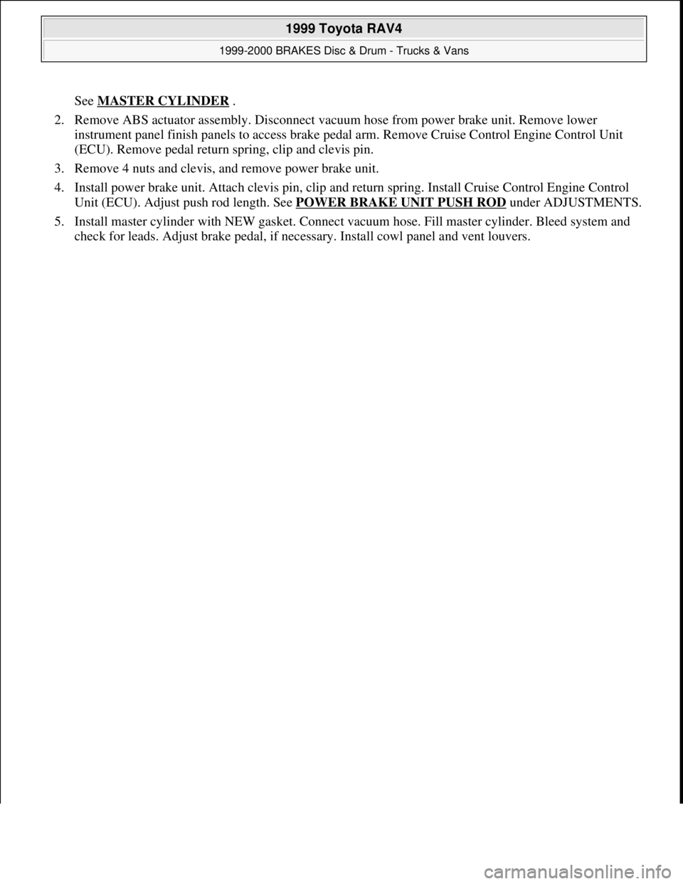
See MASTER CYLINDER .
2. Remove ABS actuator assembly. Disconnect vacuum hose from power brake unit. Remove lower
instrument panel finish panels to access brake pedal arm. Remove Cruise Control Engine Control Unit
(ECU). Remove pedal return spring, clip and clevis pin.
3. Remove 4 nuts and clevis, and remove power brake unit.
4. Install power brake unit. Attach clevis pin, clip and return spring. Install Cruise Control Engine Control
Unit (ECU). Adjust push rod length. See POWER BRAKE UNIT PUSH ROD
under ADJUSTMENTS.
5. Install master cylinder with NEW gasket. Connect vacuum hose. Fill master cylinder. Bleed system and
check for leads. Adjust brake pedal, if necessary. Install cowl panel and vent louvers.
1999 Toyota RAV4
1999-2000 BRAKES Disc & Drum - Trucks & Vans
Microsoft
Sunday, November 22, 2009 10:07:28 AMPage 26 © 2005 Mitchell Repair Information Company, LLC.
Page 402 of 1632
1999-2000 STARTING & CHARGING SYSTEMS
Generators & Regulators
DESCRIPTION & OPERATION
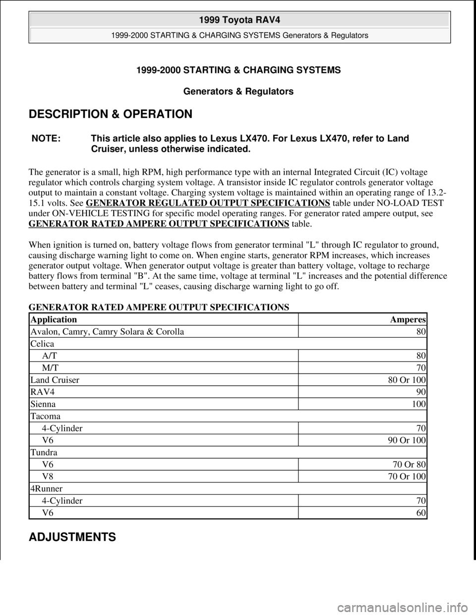
The generator is a small, high RPM, high performance type with an internal Integrated Circuit (IC) voltage
regulator which controls charging system voltage. A transistor inside IC regulator controls generator voltage
output to maintain a constant voltage. Charging system voltage is maintained within an operating range of 13.2-
15.1 volts. See GENERATOR REGULATED OUTPUT SPECIFICATIONS
table under NO-LOAD TEST
under ON-VEHICLE TESTING for specific model operating ranges. For generator rated ampere output, see
GENERATOR RATED AMPERE OUTPUT SPECIFICATIONS
table.
When ignition is turned on, battery voltage flows from generator terminal "L" through IC regulator to ground,
causing discharge warning light to come on. When engine starts, generator RPM increases, which increases
generator output voltage. When generator output voltage is greater than battery voltage, voltage to recharge
battery flows from terminal "B". At the same time, voltage at terminal "L" increases and the potential difference
between battery and terminal "L" ceases, causing discharge warning light to go off.
GENERATOR RATED AMPERE OUTPUT SPECIFICATIONS
ADJUSTMENTS
NOTE: This article also applies to Lexus LX470. For Lexus LX470, refer to Land
Cruiser, unless otherwise indicated.
ApplicationAmperes
Avalon, Camry, Camry Solara & Corolla80
Celica
A/T80
M/T70
Land Cruiser80 Or 100
RAV490
Sienna100
Tacoma
4-Cylinder70
V690 Or 100
Tundra
V670 Or 80
V870 Or 100
4Runner
4-Cylinder70
V660
1999 Toyota RAV4
1999-2000 STARTING & CHARGING SYSTEMS Generators & Regulators
1999 Toyota RAV4
1999-2000 STARTING & CHARGING SYSTEMS Generators & Regulators
Microsoft
Sunday, November 22, 2009 10:13:07 AMPage 1 © 2005 Mitchell Repair Information Company, LLC.
Microsoft
Sunday, November 22, 2009 10:13:12 AMPage 1 © 2005 Mitchell Repair Information Company, LLC.
Page 471 of 1632
1999-2000 ENGINE COOLING
Electric Cooling Fans
IDENTIFICATION
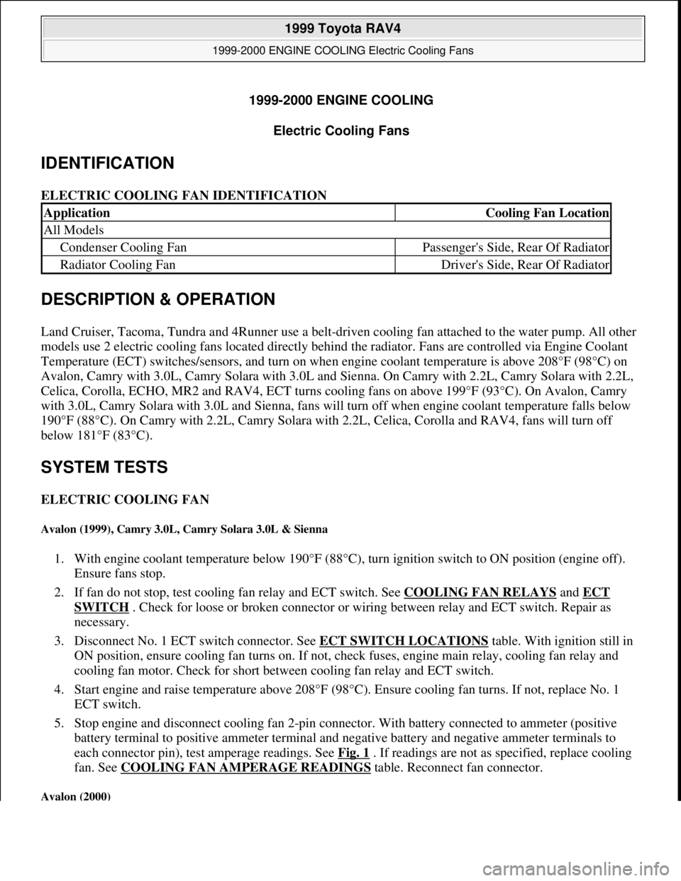
ELECTRIC COOLING FAN IDENTIFICATION
DESCRIPTION & OPERATION
Land Cruiser, Tacoma, Tundra and 4Runner use a belt-driven cooling fan attached to the water pump. All other
models use 2 electric cooling fans located directly behind the radiator. Fans are controlled via Engine Coolant
Temperature (ECT) switches/sensors, and turn on when engine coolant temperature is above 208°F (98°C) on
Avalon, Camry with 3.0L, Camry Solara with 3.0L and Sienna. On Camry with 2.2L, Camry Solara with 2.2L,
Celica, Corolla, ECHO, MR2 and RAV4, ECT turns cooling fans on above 199°F (93°C). On Avalon, Camry
with 3.0L, Camry Solara with 3.0L and Sienna, fans will turn off when engine coolant temperature falls below
190°F (88°C). On Camry with 2.2L, Camry Solara with 2.2L, Celica, Corolla and RAV4, fans will turn off
below 181°F (83°C).
SYSTEM TESTS
ELECTRIC COOLING FAN
Avalon (1999), Camry 3.0L, Camry Solara 3.0L & Sienna
1. With engine coolant temperature below 190°F (88°C), turn ignition switch to ON position (engine off).
Ensure fans stop.
2. If fan do not stop, test cooling fan relay and ECT switch. See COOLING FAN RELAYS
and ECT
SWITCH . Check for loose or broken connector or wiring between relay and ECT switch. Repair as
necessary.
3. Disconnect No. 1 ECT switch connector. See ECT SWITCH LOCATIONS
table. With ignition still in
ON position, ensure cooling fan turns on. If not, check fuses, engine main relay, cooling fan relay and
cooling fan motor. Check for short between cooling fan relay and ECT switch.
4. Start engine and raise temperature above 208°F (98°C). Ensure cooling fan turns. If not, replace No. 1
ECT switch.
5. Stop engine and disconnect cooling fan 2-pin connector. With battery connected to ammeter (positive
battery terminal to positive ammeter terminal and negative battery and negative ammeter terminals to
each connector pin), test amperage readings. See Fig. 1
. If readings are not as specified, replace cooling
fan. See COOLING FAN AMPERAGE READINGS
table. Reconnect fan connector.
Avalon (2000)
ApplicationCooling Fan Location
All Models
Condenser Cooling FanPassenger's Side, Rear Of Radiator
Radiator Cooling FanDriver's Side, Rear Of Radiator
1999 Toyota RAV4
1999-2000 ENGINE COOLING Electric Cooling Fans
1999 Toyota RAV4
1999-2000 ENGINE COOLING Electric Cooling Fans
Microsoft
Sunday, November 22, 2009 10:21:41 AMPage 1 © 2005 Mitchell Repair Information Company, LLC.
Microsoft
Sunday, November 22, 2009 10:21:45 AMPage 1 © 2005 Mitchell Repair Information Company, LLC.
Page 525 of 1632
1999 ACCESSORIES & EQUIPMENT
Cruise Control Systems - RAV4
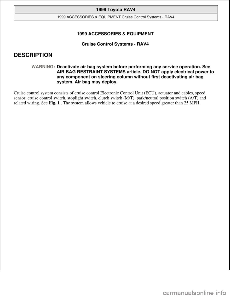
DESCRIPTION
Cruise control system consists of cruise control Electronic Control Unit (ECU), actuator and cables, speed
sensor, cruise control switch, stoplight switch, clutch switch (M/T), park/neutral position switch (A/T) and
related wirin
g. See Fig. 1 . The system allows vehicle to cruise at a desired speed greater than 25 MPH. WARNING:Deactivate air bag system before performing any service operation. See
AIR BAG RESTRAINT SYSTEMS article. DO NOT apply electrical power to
any component on steering column without first deactivating air bag
system. Air bag may deploy.
1999 Toyota RAV4
1999 ACCESSORIES & EQUIPMENT Cruise Control Systems - RAV4
1999 Toyota RAV4
1999 ACCESSORIES & EQUIPMENT Cruise Control Systems - RAV4
Microsoft
Sunday, November 22, 2009 10:52:01 AMPage 1 © 2005 Mitchell Repair Information Company, LLC.
Microsoft
Sunday, November 22, 2009 10:52:04 AMPage 1 © 2005 Mitchell Repair Information Company, LLC.
Page 526 of 1632
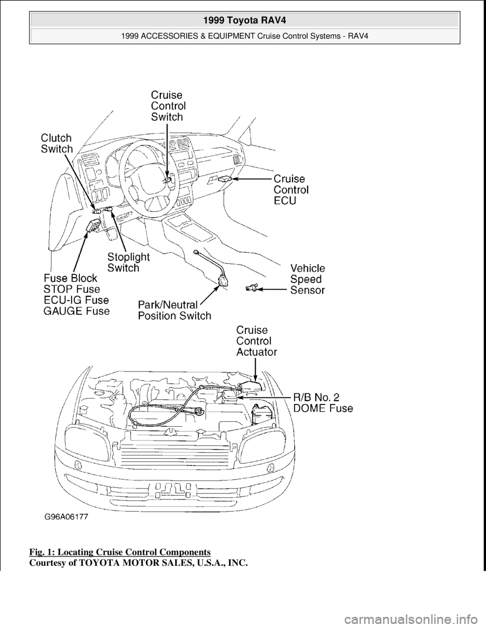
Fig. 1: Locating Cruise Control Components
Courtesy of TOYOTA MOTOR SALES, U.S.A., INC.
1999 Toyota RAV4
1999 ACCESSORIES & EQUIPMENT Cruise Control Systems - RAV4
Microsoft
Sunday, November 22, 2009 10:52:01 AMPage 2 © 2005 Mitchell Repair Information Company, LLC.