TOYOTA RAV4 2006 Service Repair Manual
Manufacturer: TOYOTA, Model Year: 2006, Model line: RAV4, Model: TOYOTA RAV4 2006Pages: 2000, PDF Size: 45.84 MB
Page 1441 of 2000
DIFFERENTIAL – REAR DIFFERENTIAL CARRIER ASSEMBLYDF–37
DF
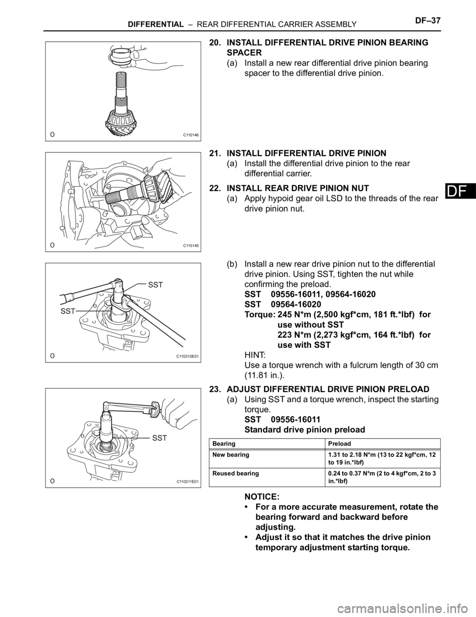
20. INSTALL DIFFERENTIAL DRIVE PINION BEARING
SPACER
(a) Install a new rear differential drive pinion bearing
spacer to the differential drive pinion.
21. INSTALL DIFFERENTIAL DRIVE PINION
(a) Install the differential drive pinion to the rear
differential carrier.
22. INSTALL REAR DRIVE PINION NUT
(a) Apply hypoid gear oil LSD to the threads of the rear
drive pinion nut.
(b) Install a new rear drive pinion nut to the differential
drive pinion. Using SST, tighten the nut while
confirming the preload.
SST 09556-16011, 09564-16020
SST 09564-16020
Torque: 245 N*m (2,500 kgf*cm, 181 ft.*lbf) for
use without SST
223 N*m (2,273 kgf*cm, 164 ft.*lbf) for
use with SST
HINT:
Use a torque wrench with a fulcrum length of 30 cm
(11.81 in.).
23. ADJUST DIFFERENTIAL DRIVE PINION PRELOAD
(a) Using SST and a torque wrench, inspect the starting
torque.
SST 09556-16011
Standard drive pinion preload
NOTICE:
• For a more accurate measurement, rotate the
bearing forward and backward before
adjusting.
• Adjust it so that it matches the drive pinion
temporary adjustment starting torque.
C110146
C110145
C110310E01
C110311E01
Bearing Preload
New bearing 1.31 to 2.18 N*m (13 to 22 kgf*cm, 12
to 19 in.*lbf)
Reused bearing 0.24 to 0.37 N*m (2 to 4 kgf*cm, 2 to 3
in.*lbf)
Page 1442 of 2000
DF–38DIFFERENTIAL – REAR DIFFERENTIAL CARRIER ASSEMBLY
DF
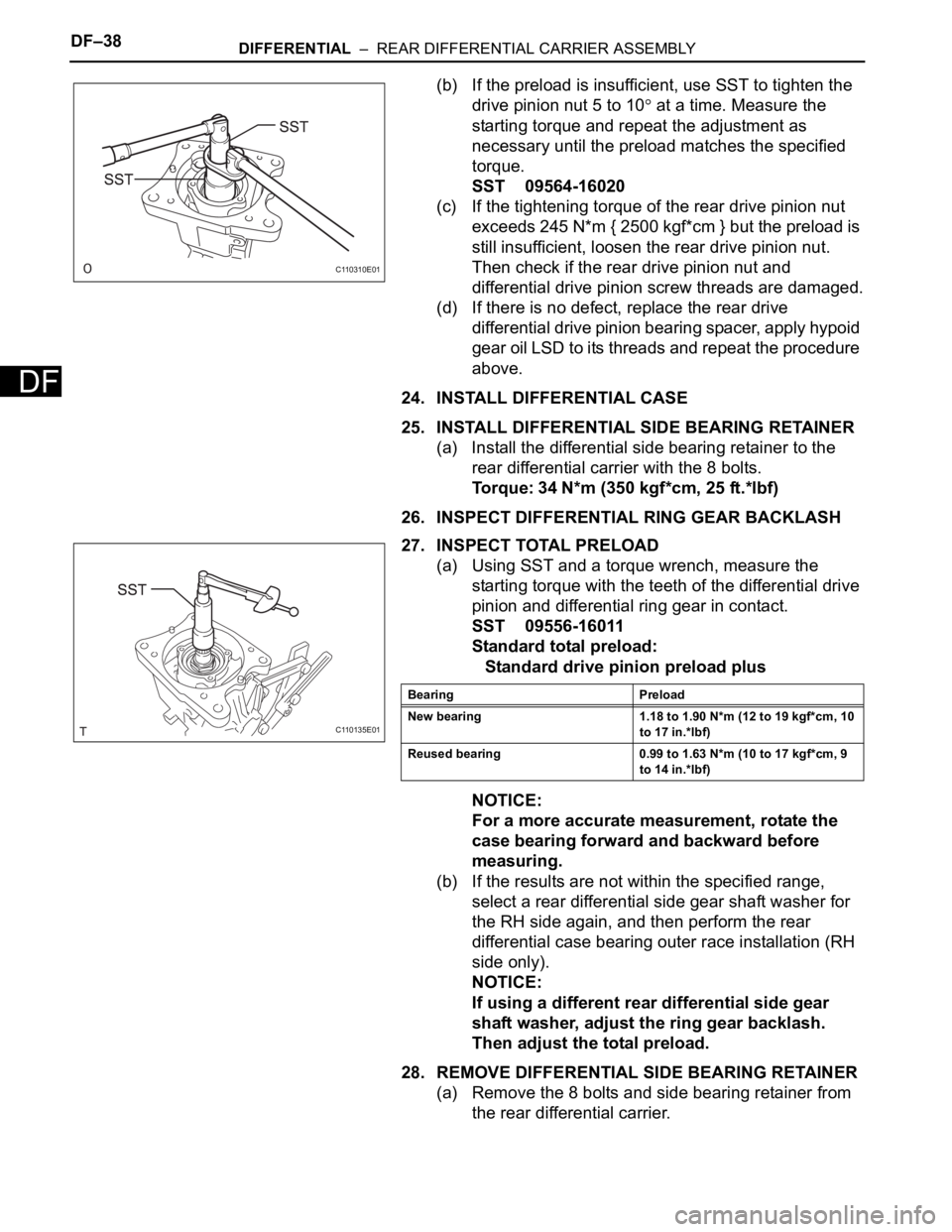
(b) If the preload is insufficient, use SST to tighten the
drive pinion nut 5 to 10
at a time. Measure the
starting torque and repeat the adjustment as
necessary until the preload matches the specified
torque.
SST 09564-16020
(c) If the tightening torque of the rear drive pinion nut
exceeds 245 N*m { 2500 kgf*cm } but the preload is
still insufficient, loosen the rear drive pinion nut.
Then check if the rear drive pinion nut and
differential drive pinion screw threads are damaged.
(d) If there is no defect, replace the rear drive
differential drive pinion bearing spacer, apply hypoid
gear oil LSD to its threads and repeat the procedure
above.
24. INSTALL DIFFERENTIAL CASE
25. INSTALL DIFFERENTIAL SIDE BEARING RETAINER
(a) Install the differential side bearing retainer to the
rear differential carrier with the 8 bolts.
Torque: 34 N*m (350 kgf*cm, 25 ft.*lbf)
26. INSPECT DIFFERENTIAL RING GEAR BACKLASH
27. INSPECT TOTAL PRELOAD
(a) Using SST and a torque wrench, measure the
starting torque with the teeth of the differential drive
pinion and differential ring gear in contact.
SST 09556-16011
Standard total preload:
Standard drive pinion preload plus
NOTICE:
For a more accurate measurement, rotate the
case bearing forward and backward before
measuring.
(b) If the results are not within the specified range,
select a rear differential side gear shaft washer for
the RH side again, and then perform the rear
differential case bearing outer race installation (RH
side only).
NOTICE:
If using a different rear differential side gear
shaft washer, adjust the ring gear backlash.
Then adjust the total preload.
28. REMOVE DIFFERENTIAL SIDE BEARING RETAINER
(a) Remove the 8 bolts and side bearing retainer from
the rear differential carrier.
C110310E01
C110135E01
Bearing Preload
New bearing 1.18 to 1.90 N*m (12 to 19 kgf*cm, 10
to 17 in.*lbf)
Reused bearing 0.99 to 1.63 N*m (10 to 17 kgf*cm, 9
to 14 in.*lbf)
Page 1443 of 2000
DIFFERENTIAL – REAR DIFFERENTIAL CARRIER ASSEMBLYDF–39
DF
29. INSTALL DIFFERENTIAL SIDE BEARING RETAINER
(a) Using white gasoline, remove grease and oil from
the alignment surfaces of the rear differential carrier
and differential side bearing retainer.
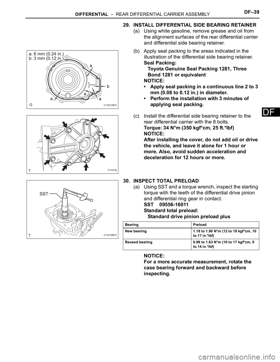
(b) Apply seal packing to the areas indicated in the
illustration of the differential side bearing retainer.
Seal Packing:
Toyota Genuine Seal Packing 1281, Three
Bond 1281 or equivalent
NOTICE:
• Apply seal packing in a continuous line 2 to 3
mm (0.08 to 0.12 in.) in diameter.
• Perform the installation with 3 minutes of
applying seal packing.
(c) Install the differential side bearing retainer to the
rear differential carrier with the 8 bolts.
Torque: 34 N*m (350 kgf*cm, 25 ft.*lbf)
NOTICE:
After installing the cover, do not add oil or drive
the vehicle, and leave it alone for 1 hour or
more. Also, avoid sudden acceleration and
deceleration for 12 hours or more.
30. INSPECT TOTAL PRELOAD
(a) Using SST and a torque wrench, inspect the starting
torque with the teeth of the differential drive pinion
and differential ring gear in contact.
SST 09556-16011
Standard total preload:
Standard drive pinion preload plus
NOTICE:
For a more accurate measurement, rotate the
case bearing forward and backward before
inspecting.
C110312E01
C110142
C110135E01
Bearing Preload
New bearing 1.18 to 1.90 N*m (12 to 19 kgf*cm, 10
to 17 in.*lbf)
Reused bearing 0.99 to 1.63 N*m (10 to 17 kgf*cm, 9
to 14 in.*lbf)
Page 1444 of 2000
DF–40DIFFERENTIAL – REAR DIFFERENTIAL CARRIER ASSEMBLY
DF
31. INSPECT DIFFERENTIAL RING GEAR BACKLASH
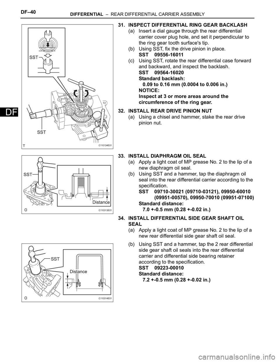
(a) Insert a dial gauge through the rear differential
carrier cover plug hole, and set it perpendicular to
the ring gear tooth surface's tip.
(b) Using SST, fix the drive pinion in place.
SST 09556-16011
(c) Using SST, rotate the rear differential case forward
and backward, and inspect the backlash.
SST 09564-16020
Standard backlash:
0.09 to 0.16 mm (0.0004 to 0.006 in.)
NOTICE:
Inspect at 3 or more areas around the
circumference of the ring gear.
32. INSTALL REAR DRIVE PINION NUT
(a) Using a chisel and hammer, stake the rear drive
pinion nut.
33. INSTALL DIAPHRAGM OIL SEAL
(a) Apply a light coat of MP grease No. 2 to the lip of a
new diaphragm oil seal.
(b) Using SST and a hammer, tap the diaphragm oil
seal into the rear differential carrier according to the
specification.
SST 09710-30021 (09710-03121), 09950-60010
(09951-00570), 09950-70010 (09951-07100)
Standard distance:
7.0 +-0.5 mm (0.28 +-0.02 in.)
34. INSTALL DIFFERENTIAL SIDE GEAR SHAFT OIL
SEAL
(a) Apply a light coat of MP grease No. 2 to the lip of a
new rear differential side gear shaft oil seal.
(b) Using SST and a hammer, tap the 2 rear differential
side gear shaft oil seals into the rear differential
carrier and differential side bearing retainer
according to the specification.
SST 09223-00010
Standard distance:
7.2 +-0.5 mm (0.28 +-0.02 in.)
C110134E01
C110313E01
C110314E01
Page 1445 of 2000
DIFFERENTIAL – REAR DIFFERENTIAL CARRIER ASSEMBLYDF–41
DF
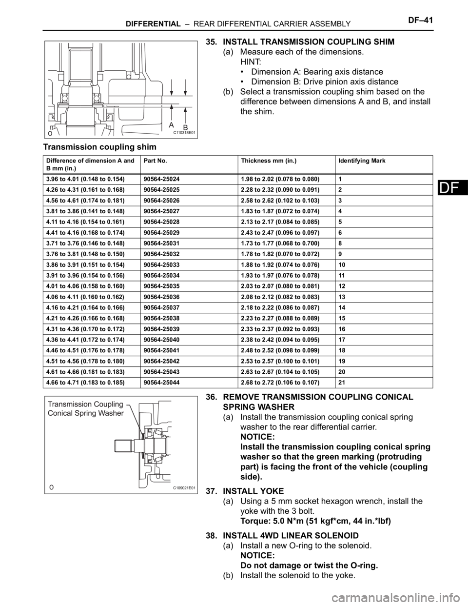
35. INSTALL TRANSMISSION COUPLING SHIM
(a) Measure each of the dimensions.
HINT:
• Dimension A: Bearing axis distance
• Dimension B: Drive pinion axis distance
(b) Select a transmission coupling shim based on the
difference between dimensions A and B, and install
the shim.
Transmission coupling shim
36. REMOVE TRANSMISSION COUPLING CONICAL
SPRING WASHER
(a) Install the transmission coupling conical spring
washer to the rear differential carrier.
NOTICE:
Install the transmission coupling conical spring
washer so that the green marking (protruding
part) is facing the front of the vehicle (coupling
side).
37. INSTALL YOKE
(a) Using a 5 mm socket hexagon wrench, install the
yoke with the 3 bolt.
Torque: 5.0 N*m (51 kgf*cm, 44 in.*lbf)
38. INSTALL 4WD LINEAR SOLENOID
(a) Install a new O-ring to the solenoid.
NOTICE:
Do not damage or twist the O-ring.
(b) Install the solenoid to the yoke.
C110318E01
Difference of dimension A and
B mm (in.)Part No. Thickness mm (in.) Identifying Mark
3.96 to 4.01 (0.148 to 0.154) 90564-25024 1.98 to 2.02 (0.078 to 0.080) 1
4.26 to 4.31 (0.161 to 0.168) 90564-25025 2.28 to 2.32 (0.090 to 0.091) 2
4.56 to 4.61 (0.174 to 0.181) 90564-25026 2.58 to 2.62 (0.102 to 0.103) 3
3.81 to 3.86 (0.141 to 0.148) 90564-25027 1.83 to 1.87 (0.072 to 0.074) 4
4.11 to 4.16 (0.154 to 0.161) 90564-25028 2.13 to 2.17 (0.084 to 0.085) 5
4.41 to 4.16 (0.168 to 0.174) 90564-25029 2.43 to 2.47 (0.096 to 0.097) 6
3.71 to 3.76 (0.146 to 0.148) 90564-25031 1.73 to 1.77 (0.068 to 0.700) 8
3.76 to 3.81 (0.148 to 0.150) 90564-25032 1.78 to 1.82 (0.070 to 0.072) 9
3.86 to 3.91 (0.151 to 0.154) 90564-25033 1.88 to 1.92 (0.074 to 0.076) 10
3.91 to 3.96 (0.154 to 0.156) 90564-25034 1.93 to 1.97 (0.076 to 0.078) 11
4.01 to 4.06 (0.158 to 0.160) 90564-25035 2.03 to 2.07 (0.080 to 0.081) 12
4.06 to 4.11 (0.160 to 0.162) 90564-25036 2.08 to 2.12 (0.082 to 0.083) 13
4.16 to 4.21 (0.164 to 0.166) 90564-25037 2.18 to 2.22 (0.086 to 0.087) 14
4.21 to 4.26 (0.166 to 0.168) 90564-25038 2.23 to 2.27 (0.088 to 0.089) 15
4.31 to 4.36 (0.170 to 0.172) 90564-25039 2.33 to 2.37 (0.092 to 0.093) 16
4.36 to 4.41 (0.172 to 0.174) 90564-25040 2.38 to 2.42 (0.094 to 0.095) 17
4.46 to 4.51 (0.176 to 0.178) 90564-25041 2.48 to 2.52 (0.098 to 0.099) 18
4.51 to 4.56 (0.178 to 0.180) 90564-25042 2.53 to 2.57 (0.100 to 0.101) 19
4.61 to 4.66 (0.181 to 0.183) 90564-25043 2.63 to 2.67 (0.104 to 0.105) 20
4.66 to 4.71 (0.183 to 0.185) 90564-25044 2.68 to 2.72 (0.106 to 0.107) 21
C109021E01
Page 1446 of 2000
DF–42DIFFERENTIAL – REAR DIFFERENTIAL CARRIER ASSEMBLY
DF
(c) Install the snap ring.
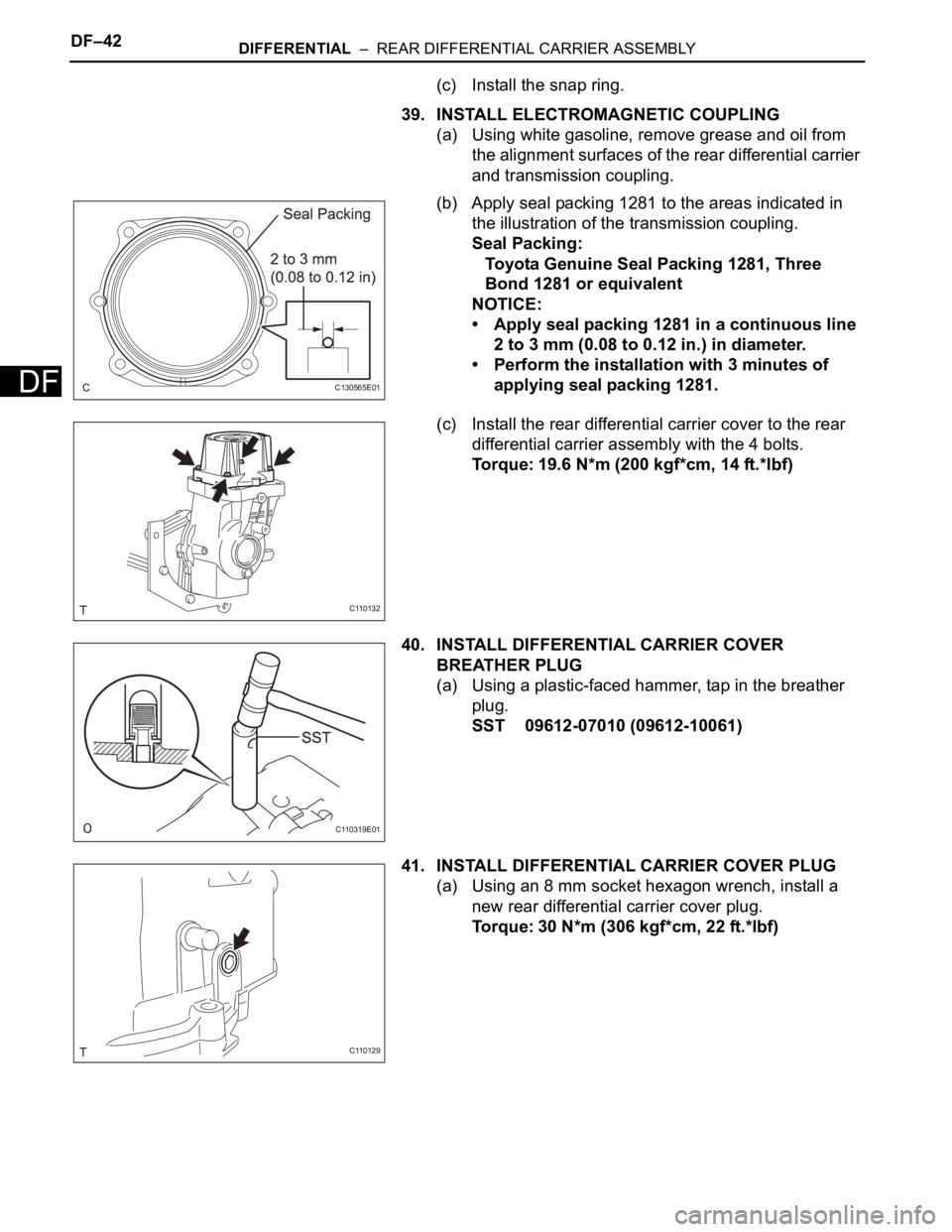
39. INSTALL ELECTROMAGNETIC COUPLING
(a) Using white gasoline, remove grease and oil from
the alignment surfaces of the rear differential carrier
and transmission coupling.
(b) Apply seal packing 1281 to the areas indicated in
the illustration of the transmission coupling.
Seal Packing:
Toyota Genuine Seal Packing 1281, Three
Bond 1281 or equivalent
NOTICE:
• Apply seal packing 1281 in a continuous line
2 to 3 mm (0.08 to 0.12 in.) in diameter.
• Perform the installation with 3 minutes of
applying seal packing 1281.
(c) Install the rear differential carrier cover to the rear
differential carrier assembly with the 4 bolts.
Torque: 19.6 N*m (200 kgf*cm, 14 ft.*lbf)
40. INSTALL DIFFERENTIAL CARRIER COVER
BREATHER PLUG
(a) Using a plastic-faced hammer, tap in the breather
plug.
SST 09612-07010 (09612-10061)
41. INSTALL DIFFERENTIAL CARRIER COVER PLUG
(a) Using an 8 mm socket hexagon wrench, install a
new rear differential carrier cover plug.
Torque: 30 N*m (306 kgf*cm, 22 ft.*lbf)
C130565E01
C110132
C110319E01
C110129
Page 1447 of 2000
DIFFERENTIAL – REAR DIFFERENTIAL CARRIER ASSEMBLYDF–43
DF
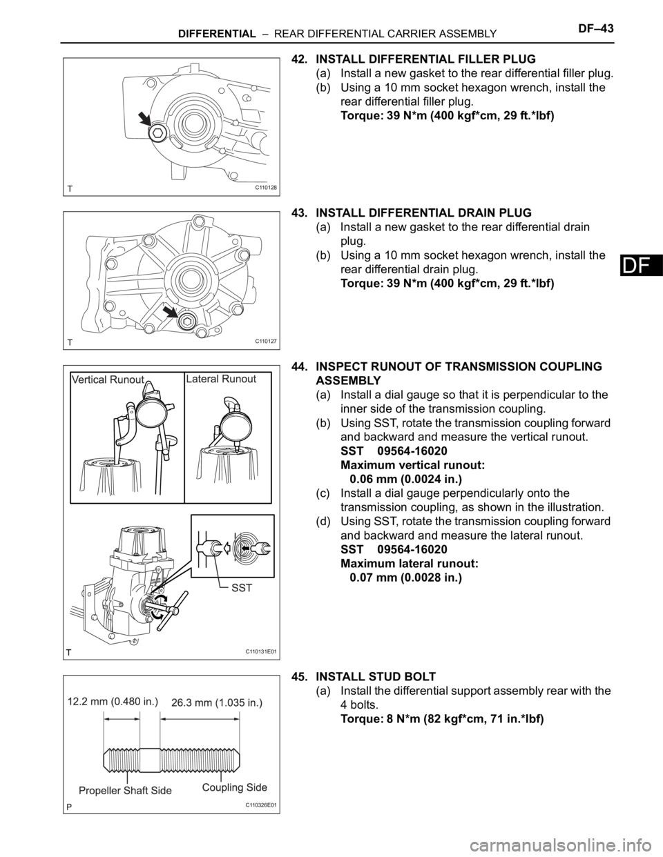
42. INSTALL DIFFERENTIAL FILLER PLUG
(a) Install a new gasket to the rear differential filler plug.
(b) Using a 10 mm socket hexagon wrench, install the
rear differential filler plug.
Torque: 39 N*m (400 kgf*cm, 29 ft.*lbf)
43. INSTALL DIFFERENTIAL DRAIN PLUG
(a) Install a new gasket to the rear differential drain
plug.
(b) Using a 10 mm socket hexagon wrench, install the
rear differential drain plug.
Torque: 39 N*m (400 kgf*cm, 29 ft.*lbf)
44. INSPECT RUNOUT OF TRANSMISSION COUPLING
ASSEMBLY
(a) Install a dial gauge so that it is perpendicular to the
inner side of the transmission coupling.
(b) Using SST, rotate the transmission coupling forward
and backward and measure the vertical runout.
SST 09564-16020
Maximum vertical runout:
0.06 mm (0.0024 in.)
(c) Install a dial gauge perpendicularly onto the
transmission coupling, as shown in the illustration.
(d) Using SST, rotate the transmission coupling forward
and backward and measure the lateral runout.
SST 09564-16020
Maximum lateral runout:
0.07 mm (0.0028 in.)
45. INSTALL STUD BOLT
(a) Install the differential support assembly rear with the
4 bolts.
Torque: 8 N*m (82 kgf*cm, 71 in.*lbf)
C110128
C110127
C110131E01
C110326E01
Page 1448 of 2000
DF–44DIFFERENTIAL – REAR DIFFERENTIAL CARRIER ASSEMBLY
DF
INSTALLATION
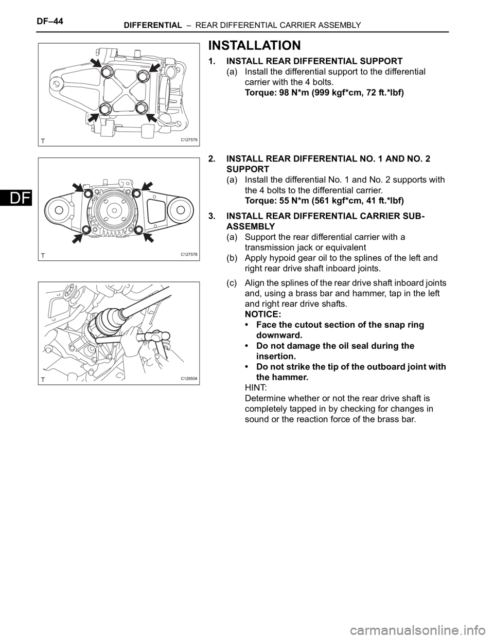
1. INSTALL REAR DIFFERENTIAL SUPPORT
(a) Install the differential support to the differential
carrier with the 4 bolts.
Torque: 98 N*m (999 kgf*cm, 72 ft.*lbf)
2. INSTALL REAR DIFFERENTIAL NO. 1 AND NO. 2
SUPPORT
(a) Install the differential No. 1 and No. 2 supports with
the 4 bolts to the differential carrier.
Torque: 55 N*m (561 kgf*cm, 41 ft.*lbf)
3. INSTALL REAR DIFFERENTIAL CARRIER SUB-
ASSEMBLY
(a) Support the rear differential carrier with a
transmission jack or equivalent
(b) Apply hypoid gear oil to the splines of the left and
right rear drive shaft inboard joints.
(c) Align the splines of the rear drive shaft inboard joints
and, using a brass bar and hammer, tap in the left
and right rear drive shafts.
NOTICE:
• Face the cutout section of the snap ring
downward.
• Do not damage the oil seal during the
insertion.
• Do not strike the tip of the outboard joint with
the hammer.
HINT:
Determine whether or not the rear drive shaft is
completely tapped in by checking for changes in
sound or the reaction force of the brass bar.
C127579
C127578
C129504
Page 1449 of 2000
DIFFERENTIAL – REAR DIFFERENTIAL CARRIER ASSEMBLYDF–45
DF
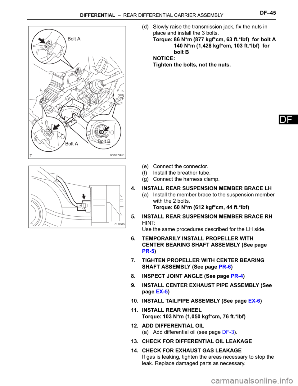
(d) Slowly raise the transmission jack, fix the nuts in
place and install the 3 bolts.
Torque: 86 N*m (877 kgf*cm, 63 ft.*lbf) for bolt A
140 N*m (1,428 kgf*cm, 103 ft.*lbf) for
bolt B
NOTICE:
Tighten the bolts, not the nuts.
(e) Connect the connector.
(f) Install the breather tube.
(g) Connect the harness clamp.
4. INSTALL REAR SUSPENSION MEMBER BRACE LH
(a) Install the member brace to the suspension member
with the 2 bolts.
Torque: 60 N*m (612 kgf*cm, 44 ft.*lbf)
5. INSTALL REAR SUSPENSION MEMBER BRACE RH
HINT:
Use the same procedures described for the LH side.
6. TEMPORARILY INSTALL PROPELLER WITH
CENTER BEARING SHAFT ASSEMBLY (See page
PR-5)
7. TIGHTEN PROPELLER WITH CENTER BEARING
SHAFT ASSEMBLY (See page PR-6)
8. INSPECT JOINT ANGLE (See page PR-4)
9. INSTALL CENTER EXHAUST PIPE ASSEMBLY (See
page EX-5)
10. INSTALL TAILPIPE ASSEMBLY (See page EX-6)
11 . I N S TA L L R E A R WH E E L
Torque: 103 N*m (1,050 kgf*cm, 76 ft.*lbf)
12. ADD DIFFERENTIAL OIL
(a) Add differential oil (see page DF-3).
13. CHECK FOR DIFFERENTIAL OIL LEAKAGE
14. CHECK FOR EXHAUST GAS LEAKAGE
If gas is leaking, tighten the areas necessary to stop the
leak. Replace damaged parts as necessary.
C129479E01
C127575
Page 1450 of 2000
AXLE – FRONT AXLE HUBAH–9
AH
REMOVAL
(2006/01- )
HINT:
• Use the same procedures for the RH side and LH side.
• The procedures listed below are the LH side.
1. REMOVE FRONT WHEEL
2. DRAIN AUTOMATIC TRANSAXLE FLUID
(a) Drain the automatic transaxle fluid for U140F (see
page AX-147).
(b) Drain the automatic transaxle fluid for U241E (see
page AX-146).
(c) Drain the automatic transaxle fluid for U151E (see
page AX-172).
(d) Drain the automatic transaxle fluid for U151F (see
page AX-173).
3. DISCONNECT CABLE FROM NEGATIVE BATTERY
TERMINAL
CAUTION:
Wait at least 90 seconds after disconnecting the
cable from the negative (-) battery terminal to
prevent airbag and seat belt pretensioner activation.
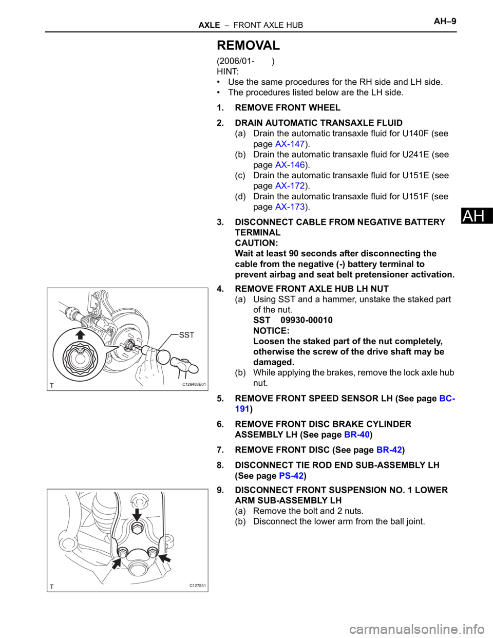
4. REMOVE FRONT AXLE HUB LH NUT
(a) Using SST and a hammer, unstake the staked part
of the nut.
SST 09930-00010
NOTICE:
Loosen the staked part of the nut completely,
otherwise the screw of the drive shaft may be
damaged.
(b) While applying the brakes, remove the lock axle hub
nut.
5. REMOVE FRONT SPEED SENSOR LH (See page BC-
191)
6. REMOVE FRONT DISC BRAKE CYLINDER
ASSEMBLY LH (See page BR-40)
7. REMOVE FRONT DISC (See page BR-42)
8. DISCONNECT TIE ROD END SUB-ASSEMBLY LH
(See page PS-42)
9. DISCONNECT FRONT SUSPENSION NO. 1 LOWER
ARM SUB-ASSEMBLY LH
(a) Remove the bolt and 2 nuts.
(b) Disconnect the lower arm from the ball joint.
C129483E01
C127531