check engine TOYOTA RAV4 2006 Service Repair Manual
[x] Cancel search | Manufacturer: TOYOTA, Model Year: 2006, Model line: RAV4, Model: TOYOTA RAV4 2006Pages: 2000, PDF Size: 45.84 MB
Page 830 of 2000
2AZ-FE EMISSION CONTROL – VENTILATION VALVEEC–19
EC
INSTALLATION
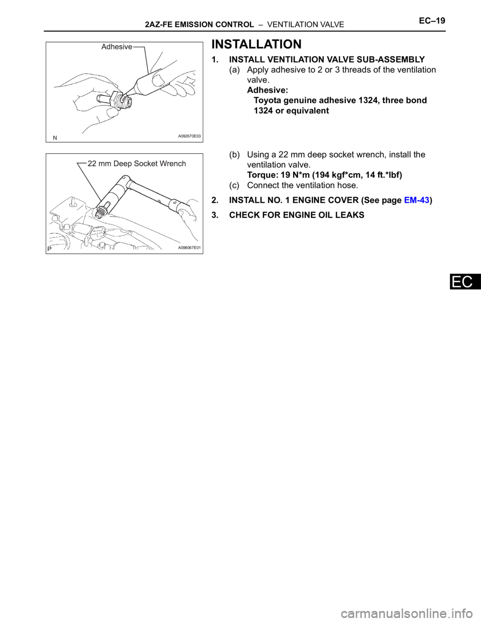
1. INSTALL VENTILATION VALVE SUB-ASSEMBLY
(a) Apply adhesive to 2 or 3 threads of the ventilation
valve.
Adhesive:
Toyota genuine adhesive 1324, three bond
1324 or equivalent
(b) Using a 22 mm deep socket wrench, install the
ventilation valve.
Torque: 19 N*m (194 kgf*cm, 14 ft.*lbf)
(c) Connect the ventilation hose.
2. INSTALL NO. 1 ENGINE COVER (See page EM-43)
3. CHECK FOR ENGINE OIL LEAKS
A092670E03
A098067E01
Page 832 of 2000
EC–82GR-FE EMISSION CONTROL – EMISSION CONTROL SYSTEM
EC
ON-VEHICLE INSPECTION
1. CHECK FUEL CUT RPM
(a) Increase the engine speed to at least 3,500 rpm.
(b) Use a sound scope to check for injector operating
noise.
(c) Check that the operating sounds stop momentarily
and then resume when the throttle lever is released.
HINT:
Measure with the A/C OFF.
Fuel return rpm:
1,400 rpm
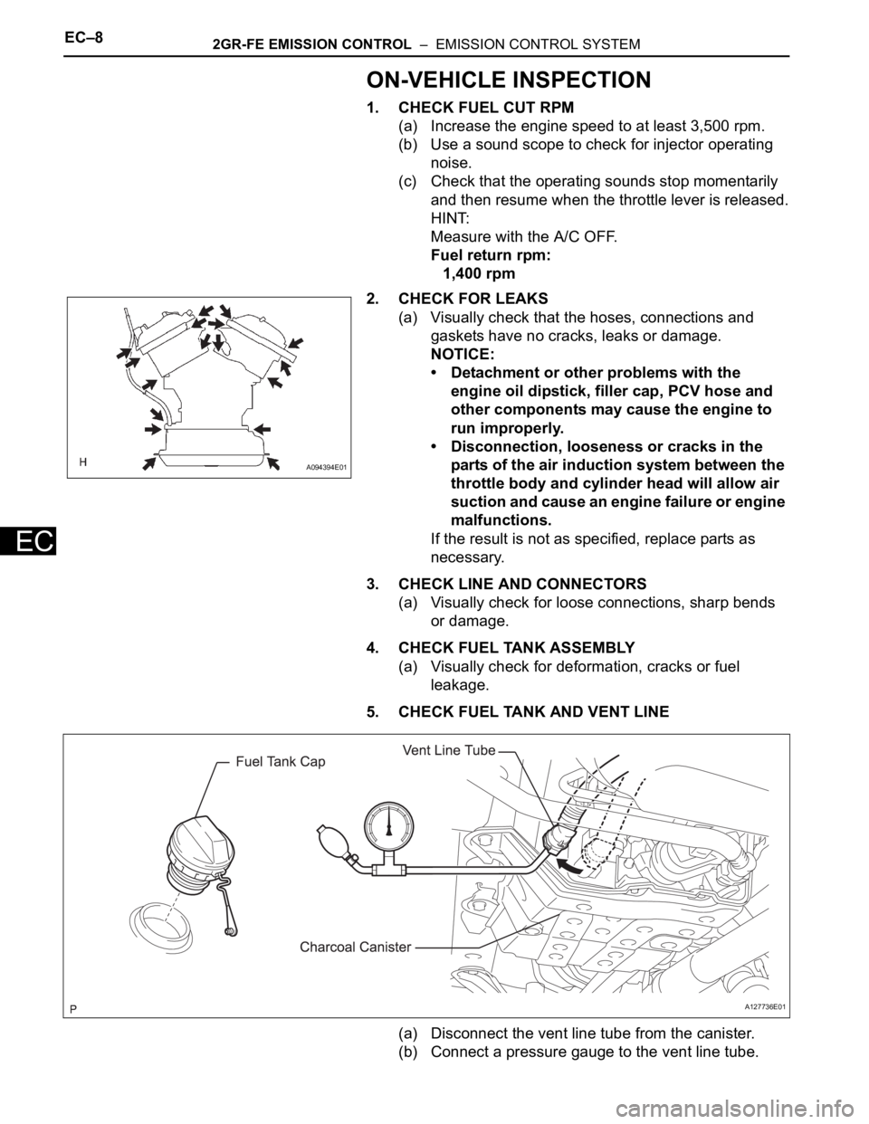
2. CHECK FOR LEAKS
(a) Visually check that the hoses, connections and
gaskets have no cracks, leaks or damage.
NOTICE:
• Detachment or other problems with the
engine oil dipstick, filler cap, PCV hose and
other components may cause the engine to
run improperly.
• Disconnection, looseness or cracks in the
parts of the air induction system between the
throttle body and cylinder head will allow air
suction and cause an engine failure or engine
malfunctions.
If the result is not as specified, replace parts as
necessary.
3. CHECK LINE AND CONNECTORS
(a) Visually check for loose connections, sharp bends
or damage.
4. CHECK FUEL TANK ASSEMBLY
(a) Visually check for deformation, cracks or fuel
leakage.
5. CHECK FUEL TANK AND VENT LINE
(a) Disconnect the vent line tube from the canister.
(b) Connect a pressure gauge to the vent line tube.
A094394E01
A127736E01
Page 837 of 2000
EC–202GR-FE EMISSION CONTROL – VENTILATION VALVE
EC
INSTALLATION
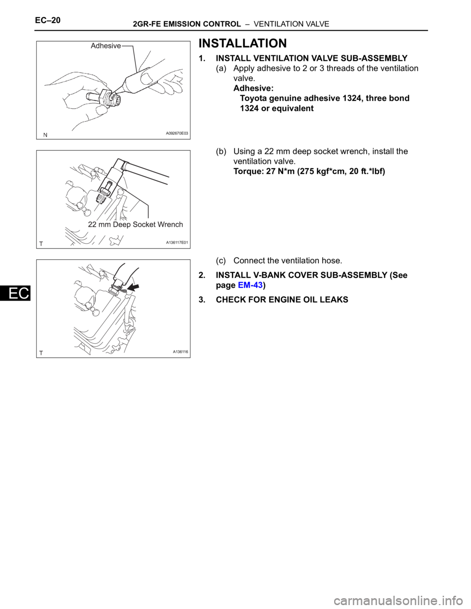
1. INSTALL VENTILATION VALVE SUB-ASSEMBLY
(a) Apply adhesive to 2 or 3 threads of the ventilation
valve.
Adhesive:
Toyota genuine adhesive 1324, three bond
1324 or equivalent
(b) Using a 22 mm deep socket wrench, install the
ventilation valve.
Torque: 27 N*m (275 kgf*cm, 20 ft.*lbf)
(c) Connect the ventilation hose.
2. INSTALL V-BANK COVER SUB-ASSEMBLY (See
page EM-43)
3. CHECK FOR ENGINE OIL LEAKS
A092670E03
A136117E01
A136116
Page 843 of 2000
2AZ-FE COOLING – WATER PUMPCO–13
CO
INSTALLATION
1. INSTALL WATER PUMP ASSEMBLY
(a) Remove any old seal packing material from the
contact surface.
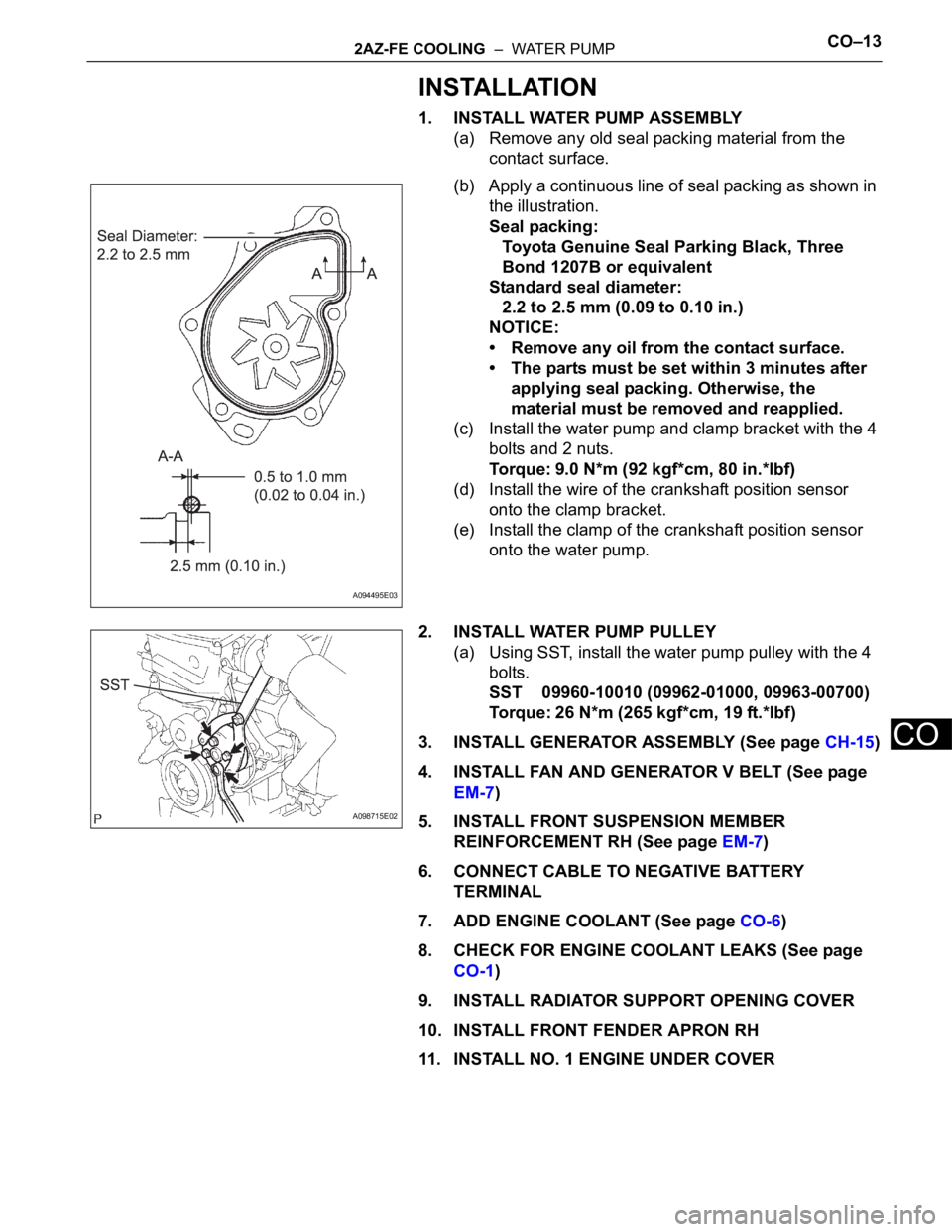
(b) Apply a continuous line of seal packing as shown in
the illustration.
Seal packing:
Toyota Genuine Seal Parking Black, Three
Bond 1207B or equivalent
Standard seal diameter:
2.2 to 2.5 mm (0.09 to 0.10 in.)
NOTICE:
• Remove any oil from the contact surface.
• The parts must be set within 3 minutes after
applying seal packing. Otherwise, the
material must be removed and reapplied.
(c) Install the water pump and clamp bracket with the 4
bolts and 2 nuts.
Torque: 9.0 N*m (92 kgf*cm, 80 in.*lbf)
(d) Install the wire of the crankshaft position sensor
onto the clamp bracket.
(e) Install the clamp of the crankshaft position sensor
onto the water pump.
2. INSTALL WATER PUMP PULLEY
(a) Using SST, install the water pump pulley with the 4
bolts.
SST 09960-10010 (09962-01000, 09963-00700)
Torque: 26 N*m (265 kgf*cm, 19 ft.*lbf)
3. INSTALL GENERATOR ASSEMBLY (See page CH-15)
4. INSTALL FAN AND GENERATOR V BELT (See page
EM-7)
5. INSTALL FRONT SUSPENSION MEMBER
REINFORCEMENT RH (See page EM-7)
6. CONNECT CABLE TO NEGATIVE BATTERY
TERMINAL
7. ADD ENGINE COOLANT (See page CO-6)
8. CHECK FOR ENGINE COOLANT LEAKS (See page
CO-1)
9. INSTALL RADIATOR SUPPORT OPENING COVER
10. INSTALL FRONT FENDER APRON RH
11. INSTALL NO. 1 ENGINE UNDER COVER
A094495E03
A098715E02
Page 844 of 2000
CO–162AZ-FE COOLING – THERMOSTAT
CO
INSTALLATION
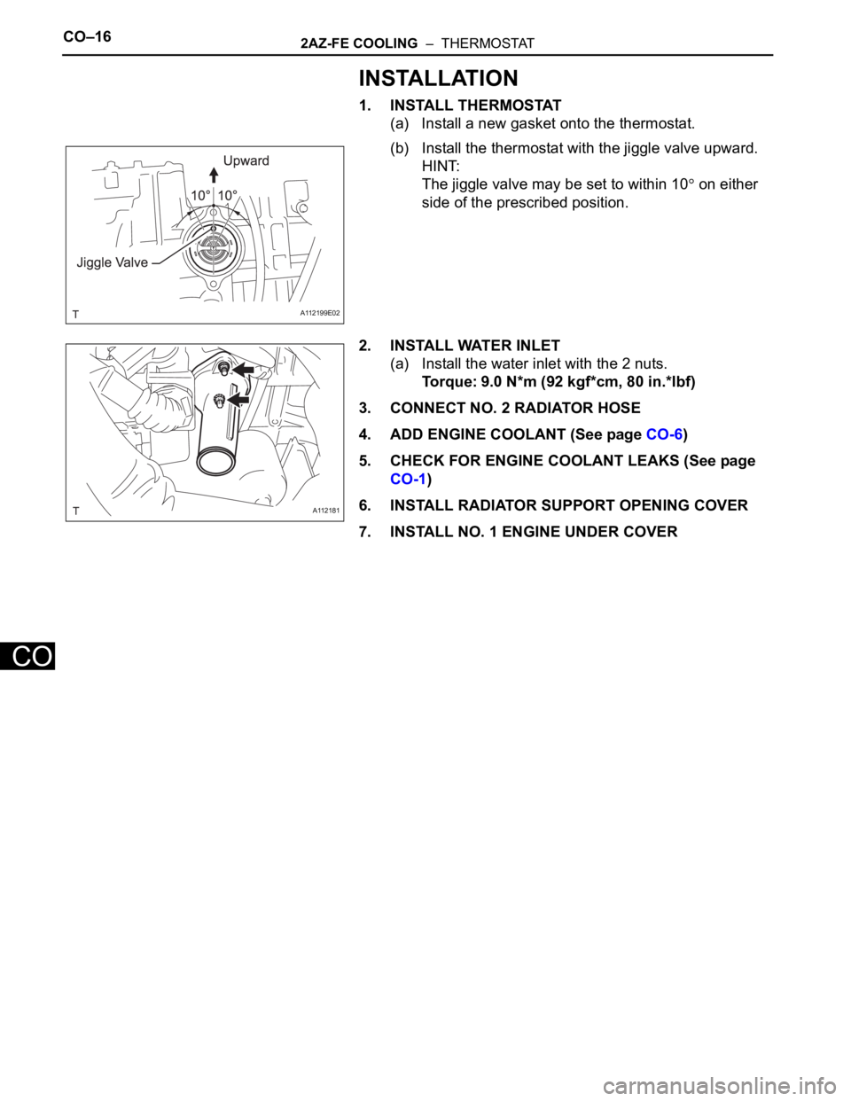
1. INSTALL THERMOSTAT
(a) Install a new gasket onto the thermostat.
(b) Install the thermostat with the jiggle valve upward.
HINT:
The jiggle valve may be set to within 10
on either
side of the prescribed position.
2. INSTALL WATER INLET
(a) Install the water inlet with the 2 nuts.
Torque: 9.0 N*m (92 kgf*cm, 80 in.*lbf)
3. CONNECT NO. 2 RADIATOR HOSE
4. ADD ENGINE COOLANT (See page CO-6)
5. CHECK FOR ENGINE COOLANT LEAKS (See page
CO-1)
6. INSTALL RADIATOR SUPPORT OPENING COVER
7. INSTALL NO. 1 ENGINE UNDER COVER
A112199E02
A112181
Page 846 of 2000

2AZ-FE COOLING – COOLING FAN MOTORCO–23
CO
INSTALLATION
1. INSTALL RADIATOR ASSEMBLY
(a) Install the radiator (see page CO-32).
2. CONNECT CABLE TO NEGATIVE BATTERY
TERMINAL
3. ADD ENGINE COOLANT (See page CO-6)
4. CHECK FOR ENGINE COOLANT LEAKS (See page
CO-1)
Page 853 of 2000
2AZ-FE COOLING – RADIATORCO–35
CO
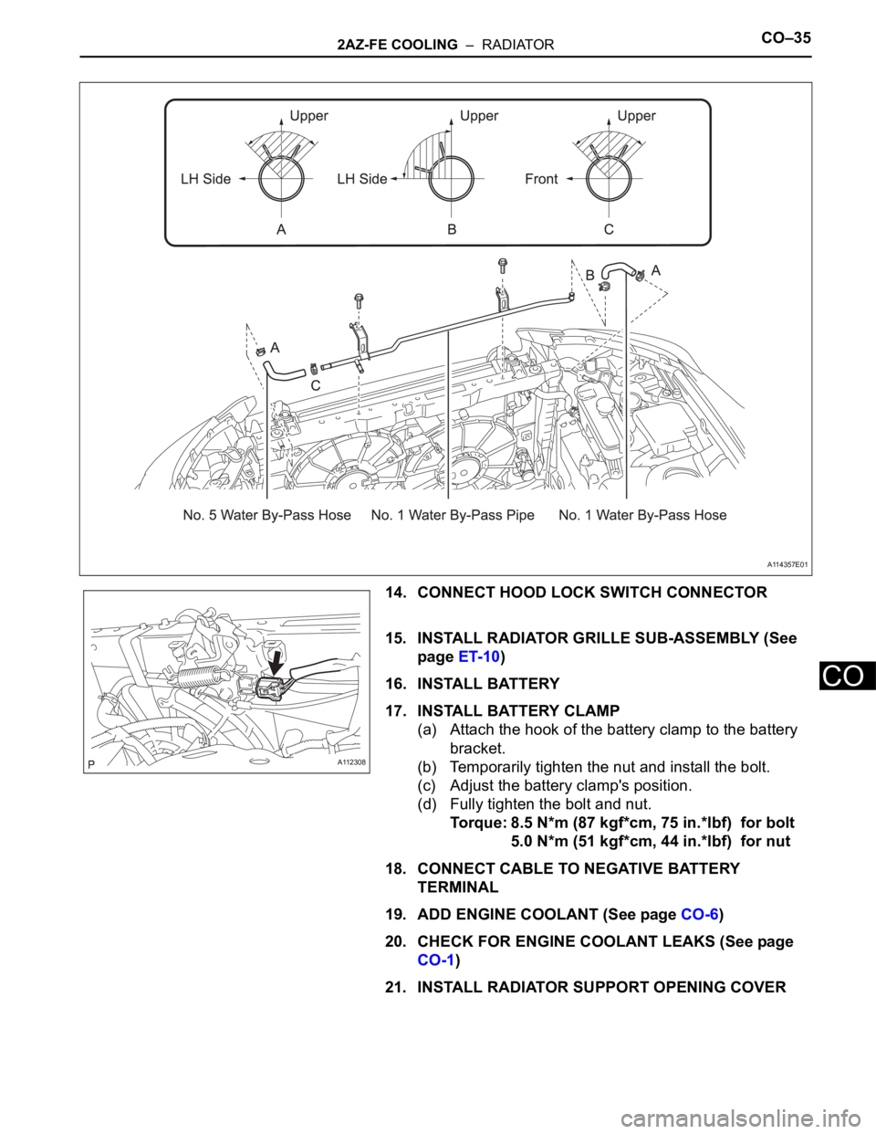
14. CONNECT HOOD LOCK SWITCH CONNECTOR
15. INSTALL RADIATOR GRILLE SUB-ASSEMBLY (See
page ET-10)
16. INSTALL BATTERY
17. INSTALL BATTERY CLAMP
(a) Attach the hook of the battery clamp to the battery
bracket.
(b) Temporarily tighten the nut and install the bolt.
(c) Adjust the battery clamp's position.
(d) Fully tighten the bolt and nut.
Torque: 8.5 N*m (87 kgf*cm, 75 in.*lbf) for bolt
5.0 N*m (51 kgf*cm, 44 in.*lbf) for nut
18. CONNECT CABLE TO NEGATIVE BATTERY
TERMINAL
19. ADD ENGINE COOLANT (See page CO-6)
20. CHECK FOR ENGINE COOLANT LEAKS (See page
CO-1)
21. INSTALL RADIATOR SUPPORT OPENING COVER
A114357E01
A112308
Page 854 of 2000
CO–62GR-FE COOLING – COOLING FAN SYSTEM
CO
ON-VEHICLE INSPECTION
HINT:
It is normal for the cooling fan to sometimes rotate when the
ignition switch is turned from ACC to ON.
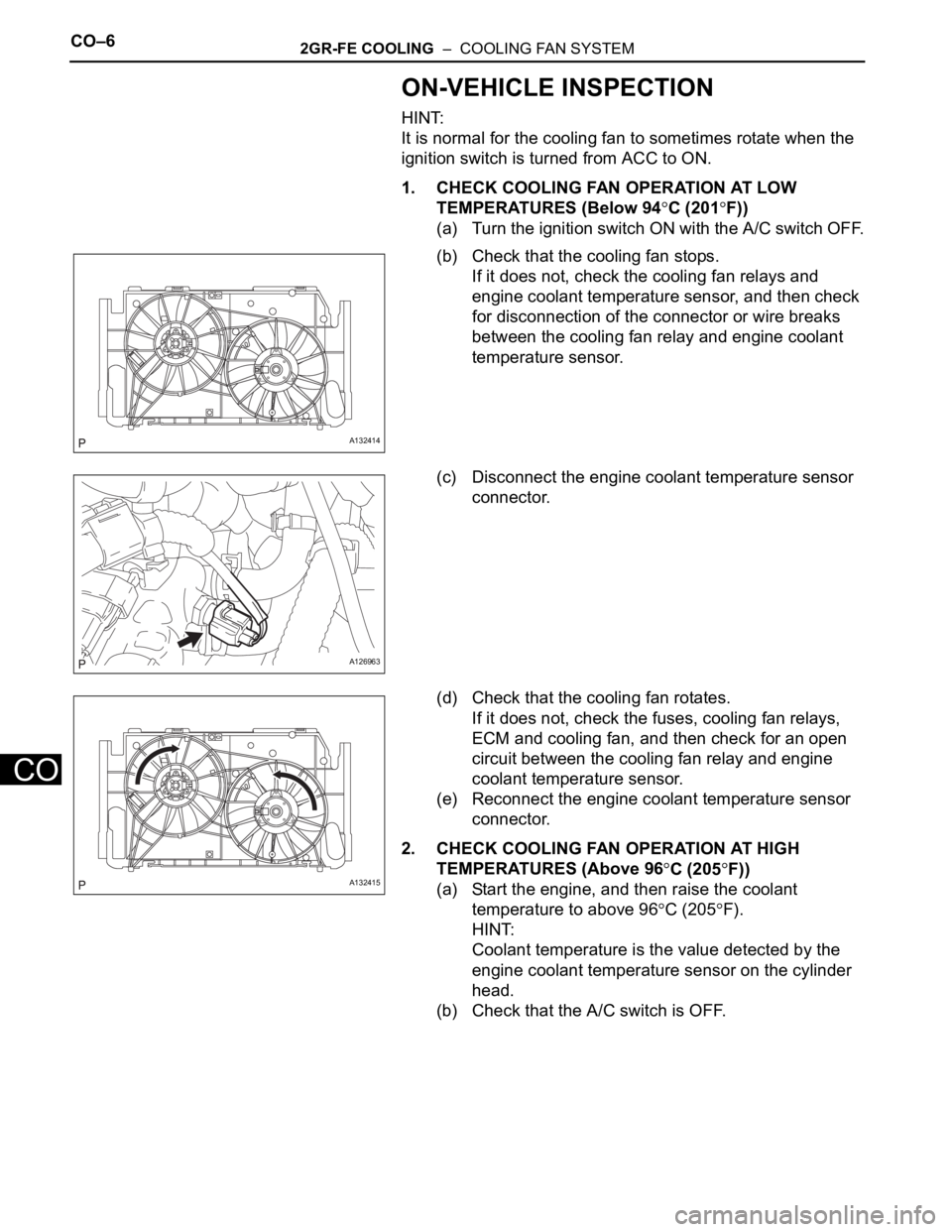
1. CHECK COOLING FAN OPERATION AT LOW
TEMPERATURES (Below 94
C (201F))
(a) Turn the ignition switch ON with the A/C switch OFF.
(b) Check that the cooling fan stops.
If it does not, check the cooling fan relays and
engine coolant temperature sensor, and then check
for disconnection of the connector or wire breaks
between the cooling fan relay and engine coolant
temperature sensor.
(c) Disconnect the engine coolant temperature sensor
connector.
(d) Check that the cooling fan rotates.
If it does not, check the fuses, cooling fan relays,
ECM and cooling fan, and then check for an open
circuit between the cooling fan relay and engine
coolant temperature sensor.
(e) Reconnect the engine coolant temperature sensor
connector.
2. CHECK COOLING FAN OPERATION AT HIGH
TEMPERATURES (Above 96
C (205F))
(a) Start the engine, and then raise the coolant
temperature to above 96
C (205F).
HINT:
Coolant temperature is the value detected by the
engine coolant temperature sensor on the cylinder
head.
(b) Check that the A/C switch is OFF.
A132414
A126963
A132415
Page 855 of 2000
2GR-FE COOLING – COOLING FAN SYSTEMCO–7
CO
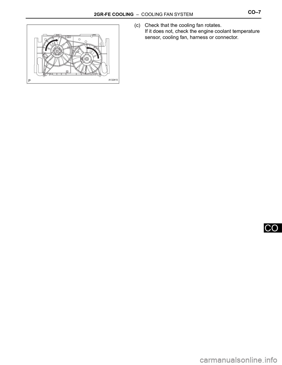
(c) Check that the cooling fan rotates.
If it does not, check the engine coolant temperature
sensor, cooling fan, harness or connector.
A132415
Page 862 of 2000
CO–222GR-FE COOLING – THERMOSTAT
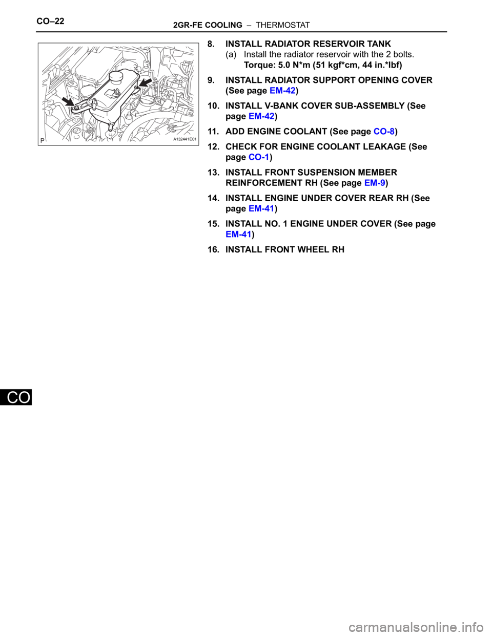
CO
8. INSTALL RADIATOR RESERVOIR TANK
(a) Install the radiator reservoir with the 2 bolts.
Torque: 5.0 N*m (51 kgf*cm, 44 in.*lbf)
9. INSTALL RADIATOR SUPPORT OPENING COVER
(See page EM-42)
10. INSTALL V-BANK COVER SUB-ASSEMBLY (See
page EM-42)
11. ADD ENGINE COOLANT (See page CO-8)
12. CHECK FOR ENGINE COOLANT LEAKAGE (See
page CO-1)
13. INSTALL FRONT SUSPENSION MEMBER
REINFORCEMENT RH (See page EM-9)
14. INSTALL ENGINE UNDER COVER REAR RH (See
page EM-41)
15. INSTALL NO. 1 ENGINE UNDER COVER (See page
EM-41)
16. INSTALL FRONT WHEEL RH
A132441E01