check engine TOYOTA RAV4 2006 Service Repair Manual
[x] Cancel search | Manufacturer: TOYOTA, Model Year: 2006, Model line: RAV4, Model: TOYOTA RAV4 2006Pages: 2000, PDF Size: 45.84 MB
Page 872 of 2000
2GR-FE COOLING – RADIATORCO–43
CO
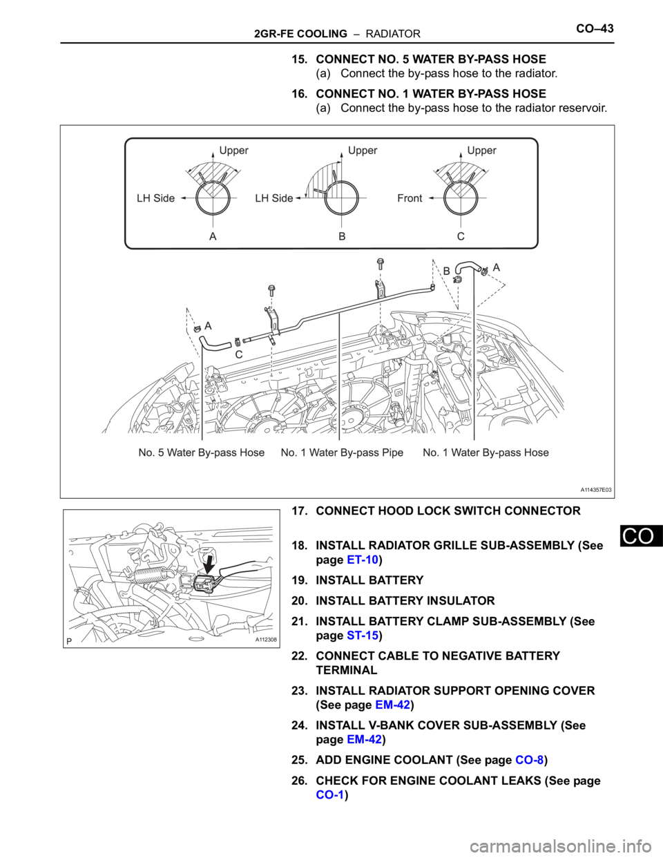
15. CONNECT NO. 5 WATER BY-PASS HOSE
(a) Connect the by-pass hose to the radiator.
16. CONNECT NO. 1 WATER BY-PASS HOSE
(a) Connect the by-pass hose to the radiator reservoir.
17. CONNECT HOOD LOCK SWITCH CONNECTOR
18. INSTALL RADIATOR GRILLE SUB-ASSEMBLY (See
page ET-10)
19. INSTALL BATTERY
20. INSTALL BATTERY INSULATOR
21. INSTALL BATTERY CLAMP SUB-ASSEMBLY (See
page ST-15)
22. CONNECT CABLE TO NEGATIVE BATTERY
TERMINAL
23. INSTALL RADIATOR SUPPORT OPENING COVER
(See page EM-42)
24. INSTALL V-BANK COVER SUB-ASSEMBLY (See
page EM-42)
25. ADD ENGINE COOLANT (See page CO-8)
26. CHECK FOR ENGINE COOLANT LEAKS (See page
CO-1)
A114357E03
A112308
Page 876 of 2000
LU–162GR-FE LUBRICATION – OIL PUMP
LU
INSPECTION
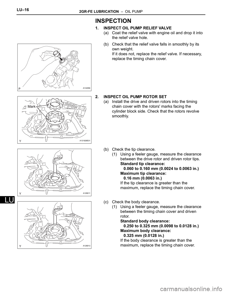
1. INSPECT OIL PUMP RELIEF VALVE
(a) Coat the relief valve with engine oil and drop it into
the relief valve hole.
(b) Check that the relief valve falls in smoothly by its
own weight.
If it does not, replace the relief valve. If necessary,
replace the timing chain cover.
2. INSPECT OIL PUMP ROTOR SET
(a) Install the drive and driven rotors into the timing
chain cover with the rotors' marks facing the
cylinder block side. Check that the rotors revolve
smoothly.
(b) Check the tip clearance.
(1) Using a feeler gauge, measure the clearance
between the drive rotor and driven rotor tips.
Standard tip clearance:
0.060 to 0.160 mm (0.0024 to 0.0063 in.)
Maximum tip clearance:
0.16 mm (0.0063 in.)
If the tip clearance is greater than the
maximum, replace the timing chain cover.
(c) Check the body clearance.
(1) Using a feeler gauge, measure the clearance
between the timing chain cover and driven
rotor.
Standard body clearance:
0.250 to 0.325 mm (0.0098 to 0.0128 in.)
Maximum body clearance:
0.325 mm (0.0128 in.)
If the body clearance is greater than the
maximum, replace the timing chain cover.
A132056
A131928E01
A128011
A128013
Page 877 of 2000
2GR-FE LUBRICATION – OIL PUMPLU–17
LU
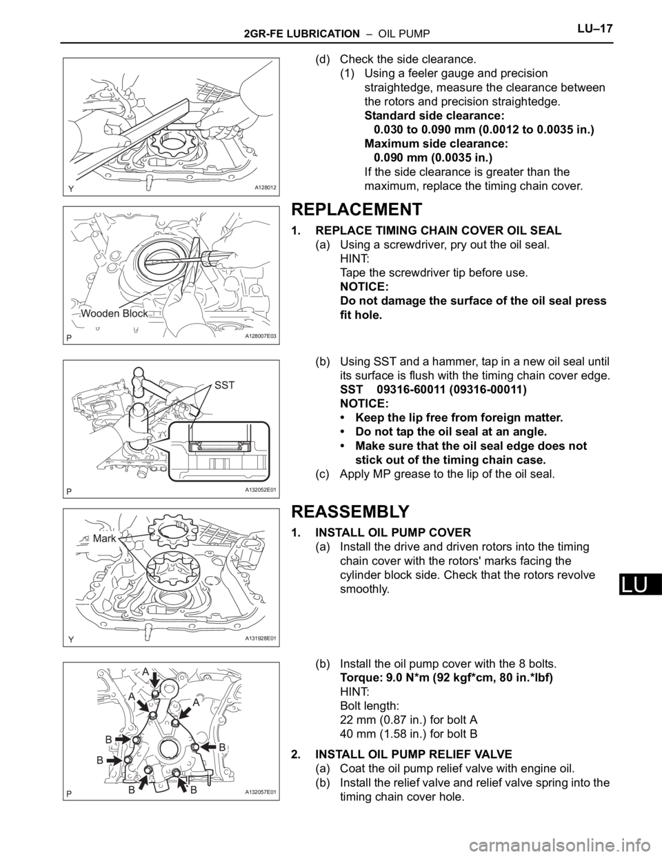
(d) Check the side clearance.
(1) Using a feeler gauge and precision
straightedge, measure the clearance between
the rotors and precision straightedge.
Standard side clearance:
0.030 to 0.090 mm (0.0012 to 0.0035 in.)
Maximum side clearance:
0.090 mm (0.0035 in.)
If the side clearance is greater than the
maximum, replace the timing chain cover.
REPLACEMENT
1. REPLACE TIMING CHAIN COVER OIL SEAL
(a) Using a screwdriver, pry out the oil seal.
HINT:
Tape the screwdriver tip before use.
NOTICE:
Do not damage the surface of the oil seal press
fit hole.
(b) Using SST and a hammer, tap in a new oil seal until
its surface is flush with the timing chain cover edge.
SST 09316-60011 (09316-00011)
NOTICE:
• Keep the lip free from foreign matter.
• Do not tap the oil seal at an angle.
• Make sure that the oil seal edge does not
stick out of the timing chain case.
(c) Apply MP grease to the lip of the oil seal.
REASSEMBLY
1. INSTALL OIL PUMP COVER
(a) Install the drive and driven rotors into the timing
chain cover with the rotors' marks facing the
cylinder block side. Check that the rotors revolve
smoothly.
(b) Install the oil pump cover with the 8 bolts.
Torque: 9.0 N*m (92 kgf*cm, 80 in.*lbf)
HINT:
Bolt length:
22 mm (0.87 in.) for bolt A
40 mm (1.58 in.) for bolt B
2. INSTALL OIL PUMP RELIEF VALVE
(a) Coat the oil pump relief valve with engine oil.
(b) Install the relief valve and relief valve spring into the
timing chain cover hole.
A128012
A128007E03
A132052E01
A131928E01
A132057E01
Page 885 of 2000
2AZ-FE IGNITION – IGNITION SYSTEMIG–5
IG
ON-VEHICLE INSPECTION
1. CHECK IGNITION COIL ASSEMBLY AND PERFORM
SPARK TEST
NOTICE:
In this section, the terms "cold" and "hot" refer to
the temperature of the coils. "Cold" means
approximately -10 to 50
C (14 to 122F). "Hot" means
approximately 50 to 100
C (122 to 212F).
(a) Check the DTCs.
NOTICE:
If a DTC is present, perform troubleshooting in
accordance with the procedure for that DTC.
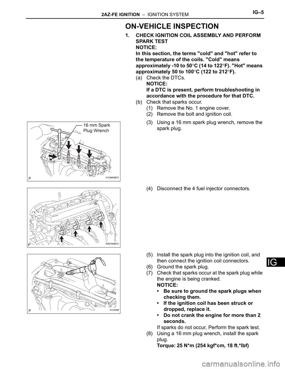
(b) Check that sparks occur.
(1) Remove the No. 1 engine cover.
(2) Remove the bolt and ignition coil.
(3) Using a 16 mm spark plug wrench, remove the
spark plug.
(4) Disconnect the 4 fuel injector connectors.
(5) Install the spark plug into the ignition coil, and
then connect the ignition coil connectors.
(6) Ground the spark plug.
(7) Check that sparks occur at the spark plug while
the engine is being cranked.
NOTICE:
• Be sure to ground the spark plugs when
checking them.
• If the ignition coil has been struck or
dropped, replace it.
• Do not crank the engine for more than 2
seconds.
If sparks do not occur, Perform the spark test.
(8) Using a 16 mm plug wrench, install the spark
plug.
Torque: 25 N*m (254 kgf*cm, 18 ft.*lbf)
A124849E01
A097448E01
A124396
Page 886 of 2000
IG–62AZ-FE IGNITION – IGNITION SYSTEM
IG
(9) Install the ignition coil with the bolt.
Torque: 9.0 N*m (92 kgf*cm, 80 in.*lbf)
(10) Connect the 4 fuel injector connectors.
(11) Install the No. 1 engine cover.
(c) Spark test flow chart.
(1) Check that the ignition coil connector is
securely connected.
Result
(2) Perform the spark test on each ignition coil.
1. Replace the ignition coil with a normal one.
2. Perform the spark test again.
Result
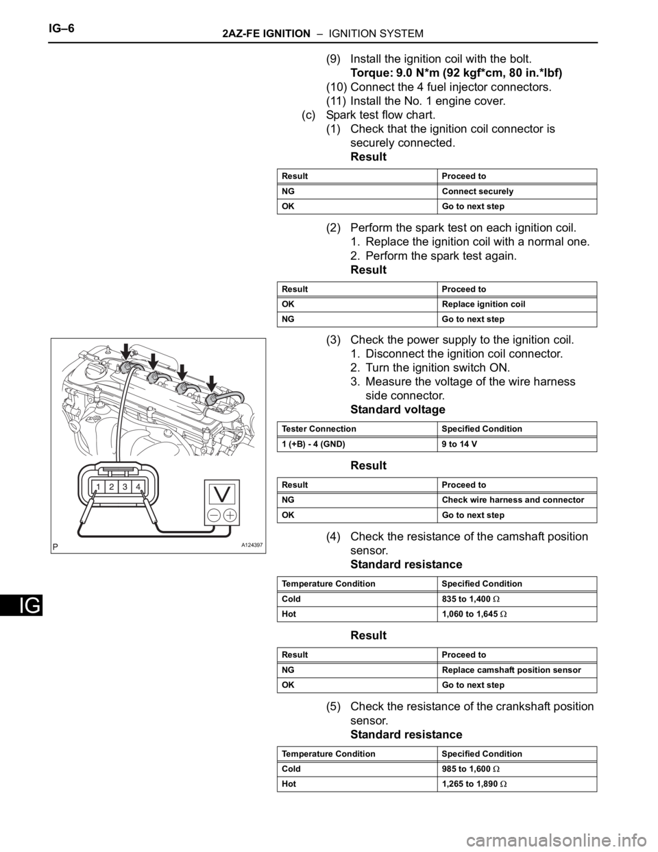
(3) Check the power supply to the ignition coil.
1. Disconnect the ignition coil connector.
2. Turn the ignition switch ON.
3. Measure the voltage of the wire harness
side connector.
Standard voltage
Result
(4) Check the resistance of the camshaft position
sensor.
Standard resistance
Result
(5) Check the resistance of the crankshaft position
sensor.
Standard resistance
Result Proceed to
NG Connect securely
OK Go to next step
Result Proceed to
OK Replace ignition coil
NG Go to next step
A124397
Tester Connection Specified Condition
1 (+B) - 4 (GND) 9 to 14 V
Result Proceed to
NG Check wire harness and connector
OK Go to next step
Temperature Condition Specified Condition
Cold 835 to 1,400
Hot 1,060 to 1,645
Result Proceed to
NG Replace camshaft position sensor
OK Go to next step
Temperature Condition Specified Condition
Cold 985 to 1,600
Hot 1,265 to 1,890
Page 887 of 2000
2AZ-FE IGNITION – IGNITION SYSTEMIG–7
IG
Result
(6) Check the IGT signal from the ECM.
Result
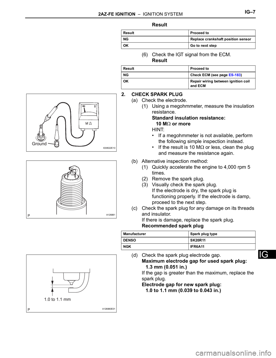
2. CHECK SPARK PLUG
(a) Check the electrode.
(1) Using a megohmmeter, measure the insulation
resistance.
Standard insulation resistance:
10 M
or more
HINT:
• If a megohmmeter is not available, perform
the following simple inspection instead.
• If the result is 10 M
or less, clean the plug
and measure the resistance again.
(b) Alternative inspection method:
(1) Quickly accelerate the engine to 4,000 rpm 5
times.
(2) Remove the spark plug.
(3) Visually check the spark plug.
If the electrode is dry, the spark plug is
functioning properly. If the electrode is damp,
proceed to the next step.
(c) Check the spark plug for any damage on its threads
and insulator.
If there is damage, replace the spark plug.
Recommended spark plug
(d) Check the spark plug electrode gap.
Maximum electrode gap for used spark plug:
1.3 mm (0.051 in.)
If the gap is greater than the maximum, replace the
spark plug.
Electrode gap for new spark plug:
1.0 to 1.1 mm (0.039 to 0.043 in.)
Result Proceed to
NG Replace crankshaft position sensor
OK Go to next step
Result Proceed to
NG Check ECM (see page ES-183)
OK Repair wiring between ignition coil
and ECM
I039522E10
A126881
Manufacturer Spark plug type
DENSO SK20R11
NGK IFR6A11
A126880E01
Page 895 of 2000
2GR-FE IGNITION – IGNITION SYSTEMIG–5
IG
ON-VEHICLE INSPECTION
1. CHECK IGNITION COIL ASSEMBLY AND PERFORM
SPARK TEST
NOTICE:
In this section, the terms "Cold" and "Hot" refer to
the temperature of the sensor. "Cold" means
approximately -10 to 50
C (14 to 122F). "Hot" means
approximately 50 to 100
C (122 to 212F).
(a) Check the DTCs.
NOTICE:
If a DTC is present, perform troubleshooting in
accordance with the procedure for that DTC.
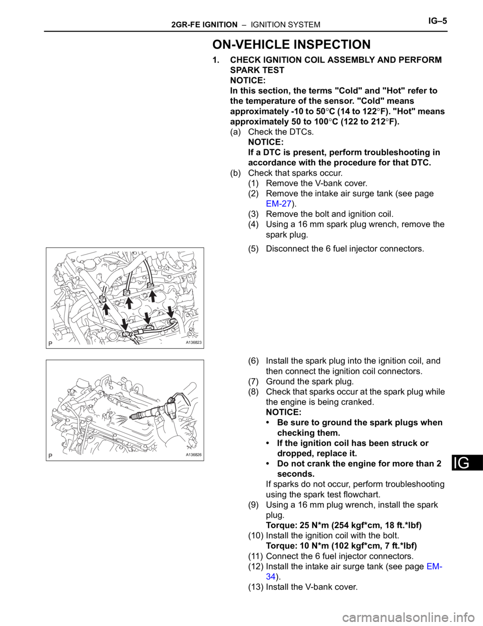
(b) Check that sparks occur.
(1) Remove the V-bank cover.
(2) Remove the intake air surge tank (see page
EM-27).
(3) Remove the bolt and ignition coil.
(4) Using a 16 mm spark plug wrench, remove the
spark plug.
(5) Disconnect the 6 fuel injector connectors.
(6) Install the spark plug into the ignition coil, and
then connect the ignition coil connectors.
(7) Ground the spark plug.
(8) Check that sparks occur at the spark plug while
the engine is being cranked.
NOTICE:
• Be sure to ground the spark plugs when
checking them.
• If the ignition coil has been struck or
dropped, replace it.
• Do not crank the engine for more than 2
seconds.
If sparks do not occur, perform troubleshooting
using the spark test flowchart.
(9) Using a 16 mm plug wrench, install the spark
plug.
Torque: 25 N*m (254 kgf*cm, 18 ft.*lbf)
(10) Install the ignition coil with the bolt.
Torque: 10 N*m (102 kgf*cm, 7 ft.*lbf)
(11) Connect the 6 fuel injector connectors.
(12) Install the intake air surge tank (see page EM-
34).
(13) Install the V-bank cover.
A136823
A136826
Page 897 of 2000
2GR-FE IGNITION – IGNITION SYSTEMIG–7
IG
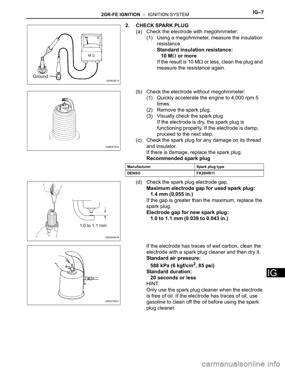
2. CHECK SPARK PLUG
(a) Check the electrode with megohmmeter:
(1) Using a megohmmeter, measure the insulation
resistance.
Standard insulation resistance:
10 M
or more
If the result is 10 M
or less, clean the plug and
measure the resistance again.
(b) Check the electrode without megohmmeter:
(1) Quickly accelerate the engine to 4,000 rpm 5
times.
(2) Remove the spark plug.
(3) Visually check the spark plug.
If the electrode is dry, the spark plug is
functioning properly. If the electrode is damp,
proceed to the next step.
(c) Check the spark plug for any damage on its thread
and insulator.
If there is damage, replace the spark plug.
Recommended spark plug
(d) Check the spark plug electrode gap.
Maximum electrode gap for used spark plug:
1.4 mm (0.055 in.)
If the gap is greater than the maximum, replace the
spark plug.
Electrode gap for new spark plug:
1.0 to 1.1 mm (0.039 to 0.043 in.)
If the electrode has traces of wet carbon, clean the
electrode with a spark plug cleaner and then dry it.
Standard air pressure:
588 kPa (6 kgf/cm
2, 85 psi)
Standard duration:
20 seconds or less
HINT:
Only use the spark plug cleaner when the electrode
is free of oil. If the electrode has traces of oil, use
gasoline to clean off the oil before using the spark
plug cleaner.
I039522E10
A088307E02
Manufacturer Spark plug type
DENSO FK20HR11
B002630E04
B062019E01
Page 928 of 2000
2GR-FE CHARGING – CHARGING SYSTEMCH–5
CH
ON-VEHICLE INSPECTION
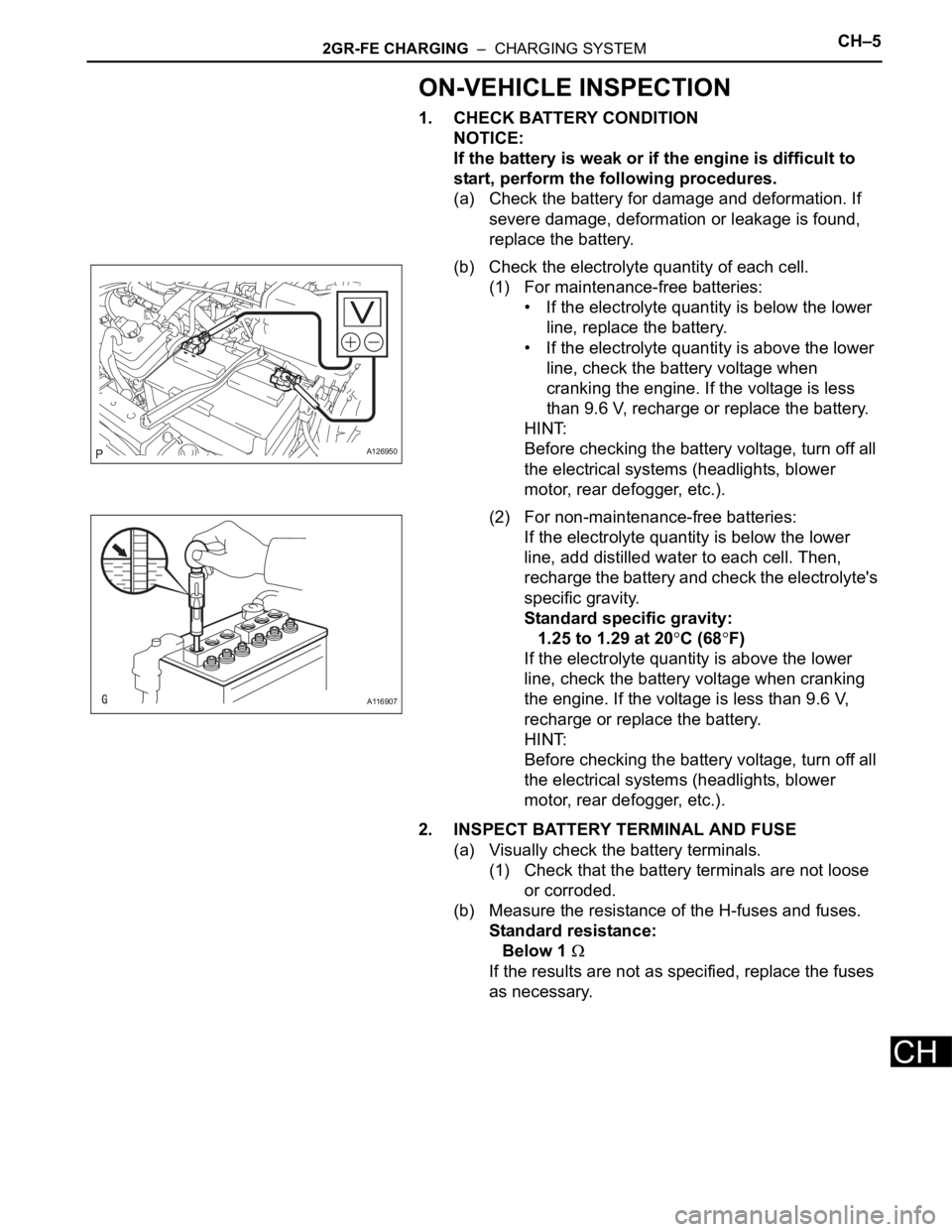
1. CHECK BATTERY CONDITION
NOTICE:
If the battery is weak or if the engine is difficult to
start, perform the following procedures.
(a) Check the battery for damage and deformation. If
severe damage, deformation or leakage is found,
replace the battery.
(b) Check the electrolyte quantity of each cell.
(1) For maintenance-free batteries:
• If the electrolyte quantity is below the lower
line, replace the battery.
• If the electrolyte quantity is above the lower
line, check the battery voltage when
cranking the engine. If the voltage is less
than 9.6 V, recharge or replace the battery.
HINT:
Before checking the battery voltage, turn off all
the electrical systems (headlights, blower
motor, rear defogger, etc.).
(2) For non-maintenance-free batteries:
If the electrolyte quantity is below the lower
line, add distilled water to each cell. Then,
recharge the battery and check the electrolyte's
specific gravity.
Standard specific gravity:
1.25 to 1.29 at 20
C (68F)
If the electrolyte quantity is above the lower
line, check the battery voltage when cranking
the engine. If the voltage is less than 9.6 V,
recharge or replace the battery.
HINT:
Before checking the battery voltage, turn off all
the electrical systems (headlights, blower
motor, rear defogger, etc.).
2. INSPECT BATTERY TERMINAL AND FUSE
(a) Visually check the battery terminals.
(1) Check that the battery terminals are not loose
or corroded.
(b) Measure the resistance of the H-fuses and fuses.
Standard resistance:
Below 1
If the results are not as specified, replace the fuses
as necessary.
A126950
A116907
Page 929 of 2000
CH–62GR-FE CHARGING – CHARGING SYSTEM
CH
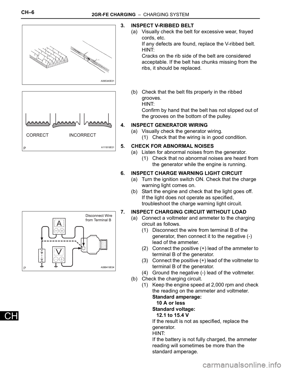
3. INSPECT V-RIBBED BELT
(a) Visually check the belt for excessive wear, frayed
cords, etc.
If any defects are found, replace the V-ribbed belt.
HINT:
Cracks on the rib side of the belt are considered
acceptable. If the belt has chunks missing from the
ribs, it should be replaced.
(b) Check that the belt fits properly in the ribbed
grooves.
HINT:
Confirm by hand that the belt has not slipped out of
the grooves on the bottom of the pulley.
4. INSPECT GENERATOR WIRING
(a) Visually check the generator wiring.
(1) Check that the wiring is in good condition.
5. CHECK FOR ABNORMAL NOISES
(a) Listen for abnormal noises from the generator.
(1) Check that no abnormal noises are heard from
the generator while the engine is running.
6. INSPECT CHARGE WARNING LIGHT CIRCUIT
(a) Turn the ignition switch ON. Check that the charge
warning light comes on.
(b) Start the engine and check that the light goes off.
If the light does not operate as specified,
troubleshoot the charge warning light circuit.
7. INSPECT CHARGING CIRCUIT WITHOUT LOAD
(a) Connect a voltmeter and ammeter to the charging
circuit as follows.
(1) Disconnect the wire from terminal B of the
generator, then connect it to the negative (-)
lead of the ammeter.
(2) Connect the positive (+) lead of the ammeter to
terminal B of the generator.
(3) Connect the positive (+) lead of the voltmeter to
terminal B of the generator.
(4) Ground the negative (-) lead of the voltmeter.
(b) Check the charging circuit.
(1) Keep the engine speed at 2,000 rpm and check
the reading on the ammeter and voltmeter.
Standard amperage:
10 A or less
Standard voltage:
12.1 to 15.4 V
If the result is not as specified, replace the
generator.
HINT:
If the battery is not fully charged, the ammeter
reading will sometimes be more than the
standard amperage.
A095340E01
A111819E01
A088419E04