current TOYOTA RAV4 2006 Service User Guide
[x] Cancel search | Manufacturer: TOYOTA, Model Year: 2006, Model line: RAV4, Model: TOYOTA RAV4 2006Pages: 2000, PDF Size: 45.84 MB
Page 102 of 2000
ENGINE - 2GR-FE ENGINE
01MEG29Y
Ignition SwitchCombination Meter
Vehicle Speed Signal
MIL
Battery Current Sensor
(Built-in Battery
Temperature Sensor)
Park / Neutral
Position Switch
Battery
Generator
Fuel Pump Relay
Fuel Pump
Vent Valve
Circuit Opening
RelayDLC3*1*2*3
CAN
ECM
Cruise Control Switch
Accelerator Pedal
Position Sensor
Stop Light Switch
Canister
Pressure
SensorLeak
Detection
Pump
Intake Air
Temp. Sensor
VSV (For
Air Intake
Control)Mass Air
Flow Meter
AirThrottle Position
Sensor
Purge VSV
Throttle
Control
Motor
*4*5
Fan
Motor No. 1Fan
Motor
No. 2
Cooling
Fan
ECUCooling
Fan
ECU
No. 1Cooling
Fan
ECU
No. 2
Fan Motor No. 1
Fan Motor No. 2
ACIS Actuator
Intake Camshaft Timing
Oil Control Valve (Bank 2)Injector Injector
Intake Camshaft Timing
Oil Control Valve (Bank 1)
Intake VVT Sensor (Bank 1)
Ignition Coil With Igniter
Exhaust VVT Sensor (Bank 1)
Exhaust Camshaft Timing
Oil Control Valve (Bank 1)
Air-fuel Ratio Sensor
(Bank1, Sensor1)
TWC
Knock
Sensor
Intake VVT
Sensor (Bank 2)
Exhaust VVT
Sensor (Bank 2)
Air-fuel Ratio Sensor
(Bank2, Sensor1)Exhaust Camshaft
Timing Oil Control
Valve (Bank 2)
Crankshaft Position
Sensor
Engine Coolant
Temperature Sensor Heated Oxygen Sensor
(Bank1, Sensor2)Heated Oxygen Sensor
(Bank2, Sensor2)TWCTWC
EG-106
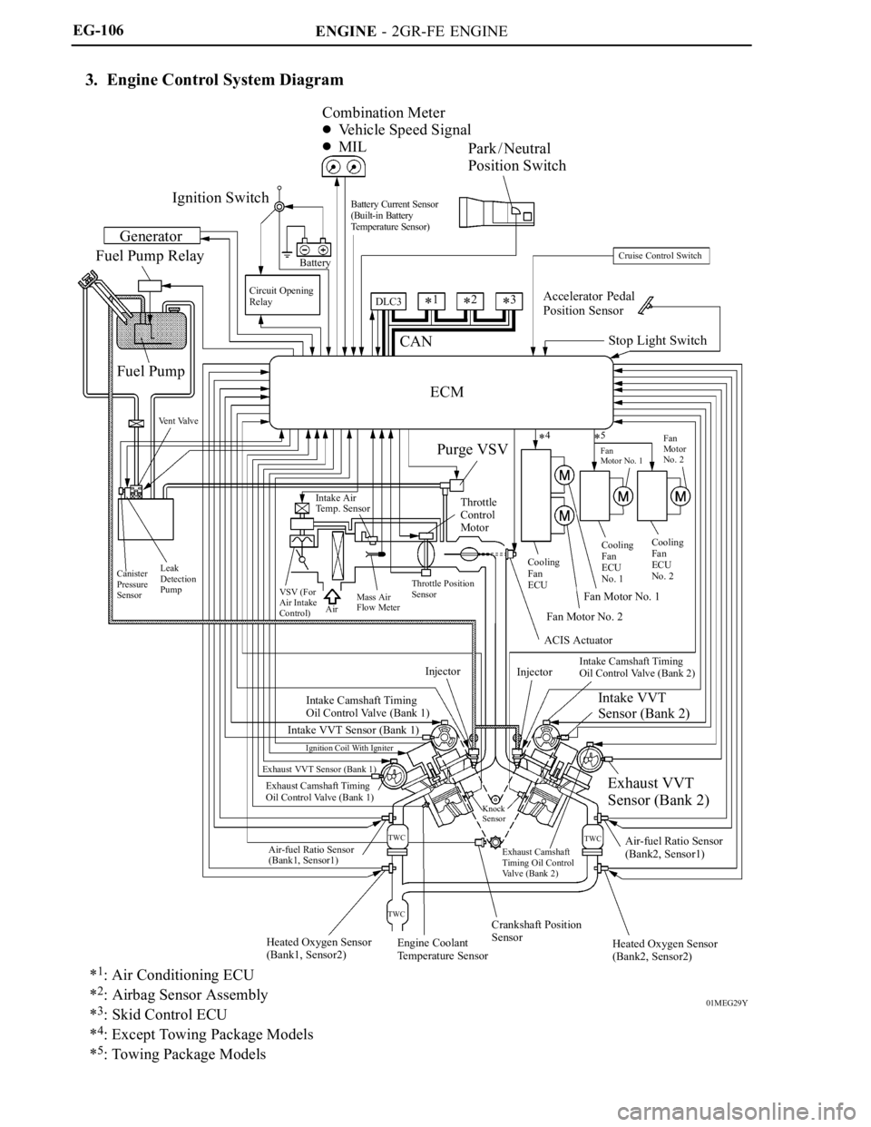
3. Engine Control System Diagram
*1: Air Conditioning ECU
*
2: Airbag Sensor Assembly
*
3: Skid Control ECU
*
4: Except Towing Package Models
*
5: Towing Package Models
Page 103 of 2000
ENGINE - 2GR-FE ENGINE
01MEG24Y
01MEG25Y
01MEG26Y
Heated Oxygen Sensor
(Bank 2, Sensor2)
Battery Current Sensor
(Built-in Battery Temperature Sensor)ECMHeated Oxygen Sensor
(Bank 1, Sensor 2)Canister Pump Module
Ve n t Va l v e
Leak Detection Pump
Canister Pressure SensorFuel Pump
VSV (for Air Intake Control)
Mass Air Flow Meter
Intake Air Temperature Sensor
Air Cleaner Cap
Vacuum Tank
Actuator (For Air Intake Control)
Combination Meter
Malfunction Indicator Lamp
DLC3
Accelerator Pedal
Position SensorEG-107
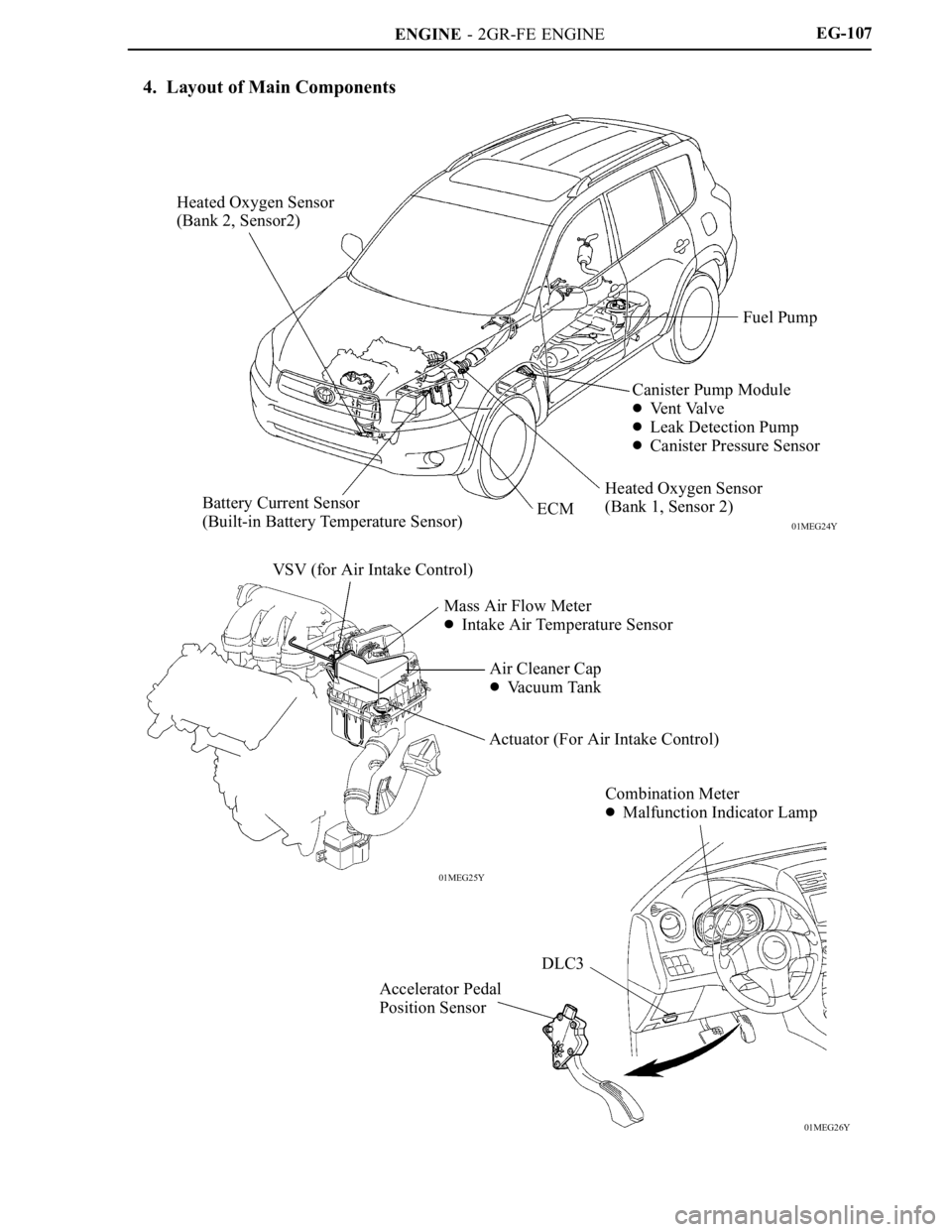
4. Layout of Main Components
Page 129 of 2000
ENGINE - 2GR-FE ENGINEEG-133
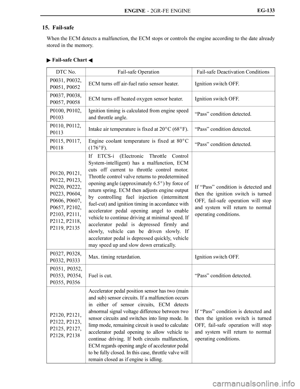
15. Fail-safe
When the ECM detects a malfunction, the ECM stops or controls the engine according to the date already
stored in the memory.
Fail-safe Chart
DTC No.Fail-safe OperationFail-safe Deactivation Conditions
P0031, P0032,
P0051, P0052ECM turns off air-fuel ratio sensor heater.Ignition switch OFF.
P0037, P0038,
P0057, P0058ECM turns off heated oxygen sensor heater.Ignition switch OFF.
P0100, P0102,
P0103Ignition timing is calculated from engine speed
and throttle angle.“Pass” condition detected.
P0110, P0112,
P0113Intake air temperature is fixed at 20C (68F).“Pass” condition detected.
P0115, P0117,
P0118Engine coolant temperature is fixed at 80C
(176
F).“Pass” condition detected.
P0120, P0121,
P0122, P0123,
P0220, P0222,
P0223, P0604,
P0606, P0607,
P0657, P2102,
P2103, P2111,
P2112, P2118,
P2119, P2135
If ETCS-i (Electronic Throttle Control
System-intelligent) has a malfunction, ECM
cuts off current to throttle control motor.
Throttle control valve returns to predetermined
opening angle (approximately 6.5
) by force of
return spring. ECM then adjusts engine output
by controlling fuel injection (intermittent
fuel-cut) and ignition timing in accordance with
accelerator pedal opening angel to enable
vehicle to continue driving at minimal speed. If
accelerator pedal is depressed firmly and
slowly, vehicle can be driven slowly. If
accelerator pedal is depressed quickly, vehicle
may speed up and slow down erratically.If “Pass” condition is detected and
then the ignition switch is turned
OFF, fail-safe operation will stop
and system will return to normal
operating conditions.
P0327, P0328,
P0332, P0333Max. timing retardation.Ignition switch OFF.
P0351, P0352,
P0353, P0354,
P0355, P0356
Fuel is cut.“Pass” condition detected.
P2120, P2121,
P2122, P2123,
P2125, P2127,
P2128, P2138
Accelerator pedal position sensor has two (main
and sub) sensor circuits. If a malfunction occurs
in either of sensor circuits, ECM detects
abnormal signal voltage difference between two
sensor circuits and switches into limp mode. In
limp mode, remaining circuit is used to calculate
accelerator pedal opening to allow vehicle to
continue driving. If both circuits malfunction,
ECM regards opening angle of accelerator pedal
to be fully closed. In this case, throttle valve will
remain closed as if engine is idling.
If “Pass” condition is detected and
then the ignition switch is turned
OFF, fail-safe operation will stop
and system will return to normal
operating conditions.
Page 209 of 2000
IN–26INTRODUCTION – REPAIR INSTRUCTION
IN
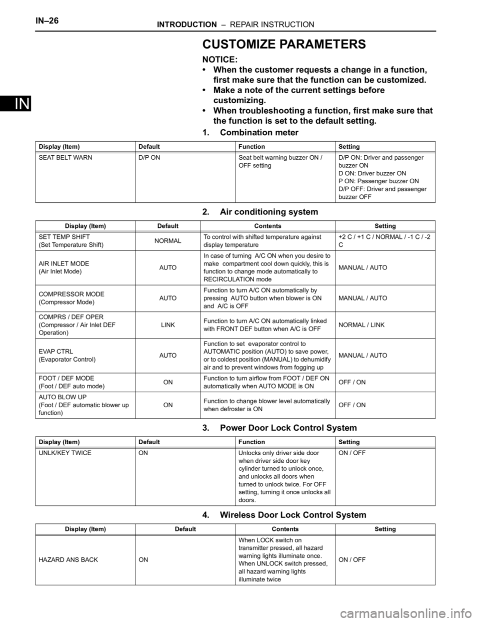
CUSTOMIZE PARAMETERS
NOTICE:
• When the customer requests a change in a function,
first make sure that the function can be customized.
• Make a note of the current settings before
customizing.
• When troubleshooting a function, first make sure that
the function is set to the default setting.
1. Combination meter
2. Air conditioning system
3. Power Door Lock Control System
4. Wireless Door Lock Control System
Display (Item) Default Function Setting
SEAT BELT WARN D/P ON Seat belt warning buzzer ON /
OFF settingD/P ON: Driver and passenger
buzzer ON
D ON: Driver buzzer ON
P ON: Passenger buzzer ON
D/P OFF: Driver and passenger
buzzer OFF
Display (Item) Default Contents Setting
SET TEMP SHIFT
(Set Temperature Shift)NORMALTo control with shifted temperature against
display temperature+2 C / +1 C / NORMAL / -1 C / -2
C
AIR INLET MODE
(Air Inlet Mode)AUTOIn case of turning A/C ON when you desire to
make compartment cool down quickly, this is
function to change mode automatically to
RECIRCULATION modeMANUAL / AUTO
COMPRESSOR MODE
(Compressor Mode)AUTOFunction to turn A/C ON automatically by
pressing AUTO button when blower is ON
and A/C is OFFMANUAL / AUTO
COMPRS / DEF OPER
(Compressor / Air Inlet DEF
Operation)LINKFunction to turn A/C ON automatically linked
with FRONT DEF button when A/C is OFFNORMAL / LINK
EVAP CTRL
(Evaporator Control)AUTOFunction to set evaporator control to
AUTOMATIC position (AUTO) to save power,
or to coldest position (MANUAL) to dehumidify
air and to prevent windows from fogging upMANUAL / AUTO
FOOT / DEF MODE
(Foot / DEF auto mode)ONFunction to turn airflow from FOOT / DEF ON
automatically when AUTO MODE is ONOFF / ON
AUTO BLOW UP
(Foot / DEF automatic blower up
function)ONFunction to change blower level automatically
when defroster is ONOFF / ON
Display (Item) Default Function Setting
UNLK/KEY TWICE ON Unlocks only driver side door
when driver side door key
cylinder turned to unlock once,
and unlocks all doors when
turned to unlock twice. For OFF
setting, turning it once unlocks all
doors.ON / OFF
Display (Item) Default Contents Setting
HAZARD ANS BACK ONWhen LOCK switch on
transmitter pressed, all hazard
warning lights illuminate once.
When UNLOCK switch pressed,
all hazard warning lights
illuminate twiceON / OFF
Page 425 of 2000
POWER STEERING – ELECTRONIC POWER STEERING SYSTEMPS–5
PS
SYSTEM DESCRIPTION
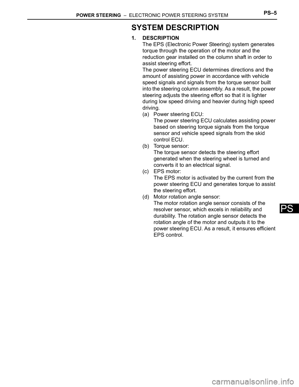
1. DESCRIPTION
The EPS (Electronic Power Steering) system generates
torque through the operation of the motor and the
reduction gear installed on the column shaft in order to
assist steering effort.
The power steering ECU determines directions and the
amount of assisting power in accordance with vehicle
speed signals and signals from the torque sensor built
into the steering column assembly. As a result, the power
steering adjusts the steering effort so that it is lighter
during low speed driving and heavier during high speed
driving.
(a) Power steering ECU:
The power steering ECU calculates assisting power
based on steering torque signals from the torque
sensor and vehicle speed signals from the skid
control ECU.
(b) Torque sensor:
The torque sensor detects the steering effort
generated when the steering wheel is turned and
converts it to an electrical signal.
(c) EPS motor:
The EPS motor is activated by the current from the
power steering ECU and generates torque to assist
the steering effort.
(d) Motor rotation angle sensor:
The motor rotation angle sensor consists of the
resolver sensor, which excels in reliability and
durability. The rotation angle sensor detects the
rotation angle of the motor and outputs it to the
power steering ECU. As a result, it ensures efficient
EPS control.
Page 439 of 2000
ENGINE IMMOBILISER – ENGINE IMMOBILISER SYSTEMEI–3
EI
SYSTEM DESCRIPTION
1. ENGINE IMMOBILISER SYSTEM DESCRIPTION
The engine immobiliser system is designed to prevent
the vehicle from being stolen. This system uses a
transponder key ECU that stores the key codes of
authorized ignition keys. If an attempt is made to start
the engine using an unauthorized key, the ECU sends a
signal to the ECM to prohibit fuel delivery and ignition,
effectively disabling the engine.
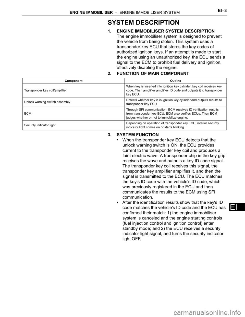
2. FUNCTION OF MAIN COMPONENT
3. SYSTEM FUNCTION
• When the transponder key ECU detects that the
unlock warning switch is ON, the ECU provides
current to the transponder key coil and produces a
faint electric wave. A transponder chip in the key grip
receives the wave and outputs a key ID code signal.
The transponder key coil receives this signal, the
transponder key amplifier amplifies it, and then the
signal is transmitted to the ECU. The ECU matches
the key's ID code with the vehicle's ID code, which
was previously registered in the ECU and then
communicates the results to the ECM using SFI
communication.
• After the identification results show that the key's ID
code matches the vehicle's ID code and the ECU has
confirmed their match: 1) the engine immobiliser
system is canceled and the engine starting controls
(fuel injection control and ignition control) enter
standby mode; and 2) the ECU receives a security
indicator light signal, and turns the security indicator
light OFF.
Component Outline
Transponder key coil/amplifierWhen key is inserted into ignition key cylinder, key coil receives key
code. Then amplifier amplifies ID code and outputs it to transponder
key ECU.
Unlock warning switch assemblyDetects whether key is in ignition key cylinder and outputs results to
transponder key ECU
ECMThrough SFI communication, ECM receives ID verification results
from transponder key ECU. ECM also verifies ECUs. Then ECM
judges whether or not to immobilize engine.
Security indicator lightDepending on operation of transponder key ECU, interior security
indicator light comes on or starts blinking
Page 476 of 2000
ES–222AZ-FE ENGINE CONTROL SYSTEM – SFI SYSTEM
ES
(b) If the test value is between the minimum and
maximum test limits, the component is functioning
normally. If not, the component is malfunctioning.
The test value is usually not near the test limits. If
the test value is near the test limits, the component
is likely to malfunction in the near future.
HINT:
The monitor result might on rare occasions be
PASS even if the malfunction indicator lamp (MIL) is
illuminated. This indicates the system malfunctioned
on a previous driving cycle. This might be caused by
an intermittent problem.
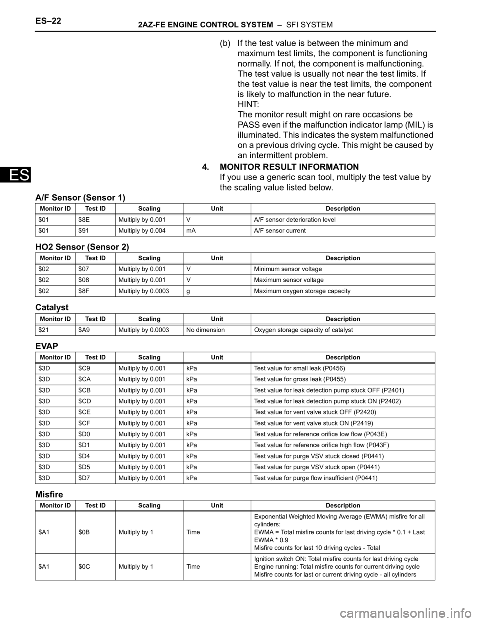
4. MONITOR RESULT INFORMATION
If you use a generic scan tool, multiply the test value by
the scaling value listed below.
A/F Sensor (Sensor 1)
HO2 Sensor (Sensor 2)
Catalyst
EVAP
Misfire
Monitor ID Test ID Scaling Unit Description
$01 $8E Multiply by 0.001 V A/F sensor deterioration level
$01 $91 Multiply by 0.004 mA A/F sensor current
Monitor ID Test ID Scaling Unit Description
$02 $07 Multiply by 0.001 V Minimum sensor voltage
$02 $08 Multiply by 0.001 V Maximum sensor voltage
$02 $8F Multiply by 0.0003 g Maximum oxygen storage capacity
Monitor ID Test ID Scaling Unit Description
$21 $A9 Multiply by 0.0003 No dimension Oxygen storage capacity of catalyst
Monitor ID Test ID Scaling Unit Description
$3D $C9 Multiply by 0.001 kPa Test value for small leak (P0456)
$3D $CA Multiply by 0.001 kPa Test value for gross leak (P0455)
$3D $CB Multiply by 0.001 kPa Test value for leak detection pump stuck OFF (P2401)
$3D $CD Multiply by 0.001 kPa Test value for leak detection pump stuck ON (P2402)
$3D $CE Multiply by 0.001 kPa Test value for vent valve stuck OFF (P2420)
$3D $CF Multiply by 0.001 kPa Test value for vent valve stuck ON (P2419)
$3D $D0 Multiply by 0.001 kPa Test value for reference orifice low flow (P043E)
$3D $D1 Multiply by 0.001 kPa Test value for reference orifice high flow (P043F)
$3D $D4 Multiply by 0.001 kPa Test value for purge VSV stuck closed (P0441)
$3D $D5 Multiply by 0.001 kPa Test value for purge VSV stuck open (P0441)
$3D $D7 Multiply by 0.001 kPa Test value for purge flow insufficient (P0441)
Monitor ID Test ID Scaling Unit Description
$A1 $0B Multiply by 1 TimeExponential Weighted Moving Average (EWMA) misfire for all
cylinders:
EWMA = Total misfire counts for last driving cycle * 0.1 + Last
EWMA * 0.9
Misfire counts for last 10 driving cycles - Total
$A1 $0C Multiply by 1 TimeIgnition switch ON: Total misfire counts for last driving cycle
Engine running: Total misfire counts for current driving cycle
Misfire counts for last or current driving cycle - all cylinders
Page 477 of 2000
2AZ-FE ENGINE CONTROL SYSTEM – SFI SYSTEMES–23
ES
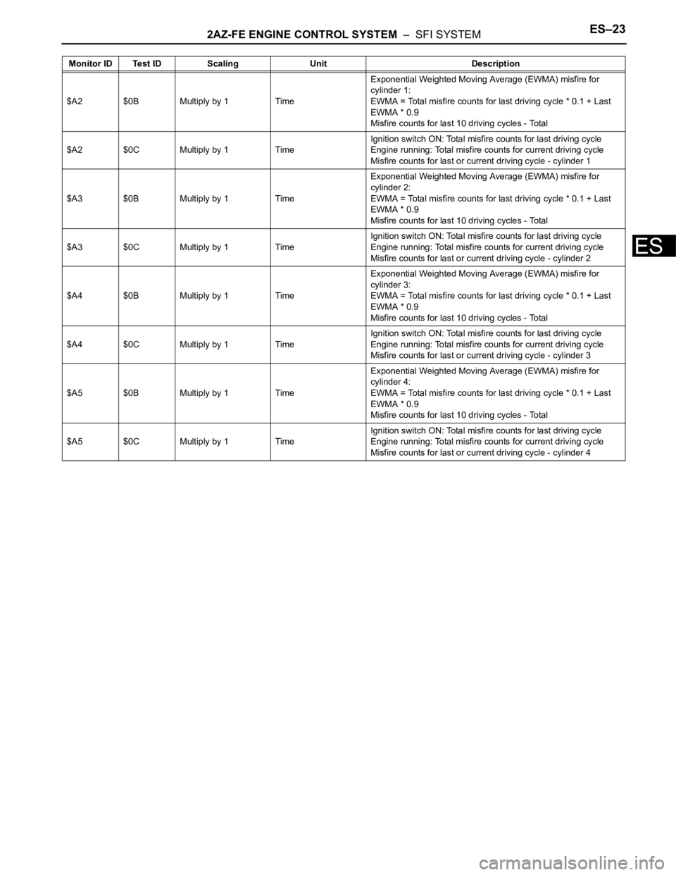
$A2 $0B Multiply by 1 TimeExponential Weighted Moving Average (EWMA) misfire for
cylinder 1:
EWMA = Total misfire counts for last driving cycle * 0.1 + Last
EWMA * 0.9
Misfire counts for last 10 driving cycles - Total
$A2 $0C Multiply by 1 TimeIgnition switch ON: Total misfire counts for last driving cycle
Engine running: Total misfire counts for current driving cycle
Misfire counts for last or current driving cycle - cylinder 1
$A3 $0B Multiply by 1 TimeExponential Weighted Moving Average (EWMA) misfire for
cylinder 2:
EWMA = Total misfire counts for last driving cycle * 0.1 + Last
EWMA * 0.9
Misfire counts for last 10 driving cycles - Total
$A3 $0C Multiply by 1 TimeIgnition switch ON: Total misfire counts for last driving cycle
Engine running: Total misfire counts for current driving cycle
Misfire counts for last or current driving cycle - cylinder 2
$A4 $0B Multiply by 1 TimeExponential Weighted Moving Average (EWMA) misfire for
cylinder 3:
EWMA = Total misfire counts for last driving cycle * 0.1 + Last
EWMA * 0.9
Misfire counts for last 10 driving cycles - Total
$A4 $0C Multiply by 1 TimeIgnition switch ON: Total misfire counts for last driving cycle
Engine running: Total misfire counts for current driving cycle
Misfire counts for last or current driving cycle - cylinder 3
$A5 $0B Multiply by 1 TimeExponential Weighted Moving Average (EWMA) misfire for
cylinder 4:
EWMA = Total misfire counts for last driving cycle * 0.1 + Last
EWMA * 0.9
Misfire counts for last 10 driving cycles - Total
$A5 $0C Multiply by 1 TimeIgnition switch ON: Total misfire counts for last driving cycle
Engine running: Total misfire counts for current driving cycle
Misfire counts for last or current driving cycle - cylinder 4 Monitor ID Test ID Scaling Unit Description
Page 487 of 2000
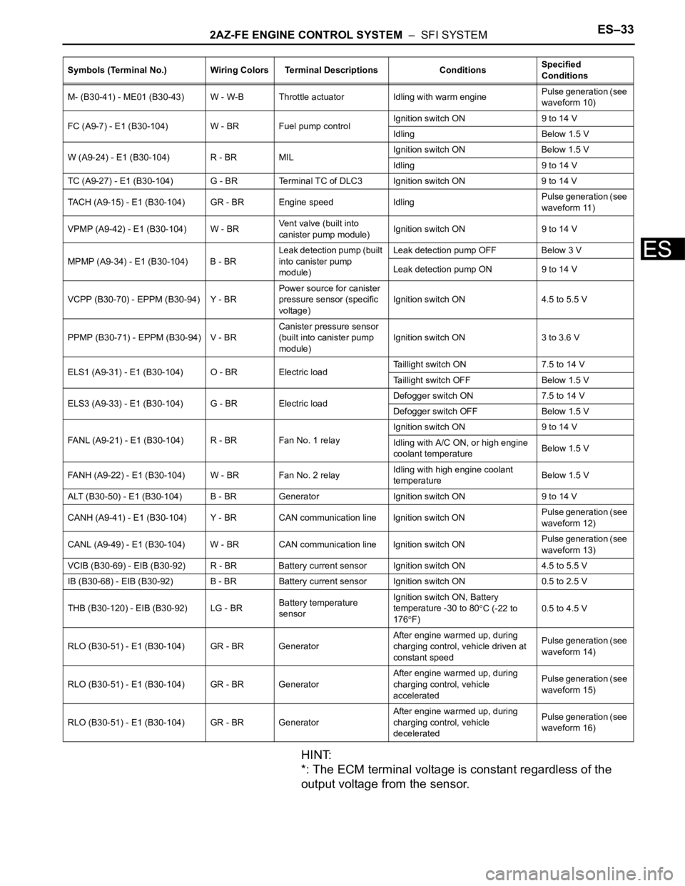
2AZ-FE ENGINE CONTROL SYSTEM – SFI SYSTEMES–33
ES
HINT:
*: The ECM terminal voltage is constant regardless of the
output voltage from the sensor.
M- (B30-41) - ME01 (B30-43) W - W-B Throttle actuator Idling with warm enginePulse generation (see
waveform 10)
FC (A9-7) - E1 (B30-104) W - BR Fuel pump controlIgnition switch ON 9 to 14 V
Idling Below 1.5 V
W (A9-24) - E1 (B30-104) R - BR MILIgnition switch ON Below 1.5 V
Idling 9 to 14 V
TC (A9-27) - E1 (B30-104) G - BR Terminal TC of DLC3 Ignition switch ON 9 to 14 V
TACH (A9-15) - E1 (B30-104) GR - BR Engine speed IdlingPulse generation (see
waveform 11)
VPMP (A9-42) - E1 (B30-104) W - BRVent valve (built into
canister pump module)Ignition switch ON 9 to 14 V
MPMP (A9-34) - E1 (B30-104) B - BRLeak detection pump (built
into canister pump
module)Leak detection pump OFF Below 3 V
Leak detection pump ON 9 to 14 V
VCPP (B30-70) - EPPM (B30-94) Y - BRPower source for canister
pressure sensor (specific
voltage)Ignition switch ON 4.5 to 5.5 V
PPMP (B30-71) - EPPM (B30-94) V - BRCanister pressure sensor
(built into canister pump
module)Ignition switch ON 3 to 3.6 V
ELS1 (A9-31) - E1 (B30-104) O - BR Electric loadTaillight switch ON 7.5 to 14 V
Taillight switch OFF Below 1.5 V
ELS3 (A9-33) - E1 (B30-104) G - BR Electric loadDefogger switch ON 7.5 to 14 V
Defogger switch OFF Below 1.5 V
FANL (A9-21) - E1 (B30-104) R - BR Fan No. 1 relayIgnition switch ON 9 to 14 V
Idling with A/C ON, or high engine
coolant temperatureBelow 1.5 V
FANH (A9-22) - E1 (B30-104) W - BR Fan No. 2 relayIdling with high engine coolant
temperatureBelow 1.5 V
ALT (B30-50) - E1 (B30-104) B - BR Generator Ignition switch ON 9 to 14 V
CANH (A9-41) - E1 (B30-104) Y - BR CAN communication line Ignition switch ONPulse generation (see
waveform 12)
CANL (A9-49) - E1 (B30-104) W - BR CAN communication line Ignition switch ONPulse generation (see
waveform 13)
VCIB (B30-69) - EIB (B30-92) R - BR Battery current sensor Ignition switch ON 4.5 to 5.5 V
IB (B30-68) - EIB (B30-92) B - BR Battery current sensor Ignition switch ON 0.5 to 2.5 V
THB (B30-120) - EIB (B30-92) LG - BRBattery temperature
sensorIgnition switch ON, Battery
temperature -30 to 80
C (-22 to
176
F)0.5 to 4.5 V
RLO (B30-51) - E1 (B30-104) GR - BR GeneratorAfter engine warmed up, during
charging control, vehicle driven at
constant speedPulse generation (see
waveform 14)
RLO (B30-51) - E1 (B30-104) GR - BR GeneratorAfter engine warmed up, during
charging control, vehicle
acceleratedPulse generation (see
waveform 15)
RLO (B30-51) - E1 (B30-104) GR - BR GeneratorAfter engine warmed up, during
charging control, vehicle
deceleratedPulse generation (see
waveform 16) Symbols (Terminal No.) Wiring Colors Terminal Descriptions ConditionsSpecified
Conditions
Page 495 of 2000
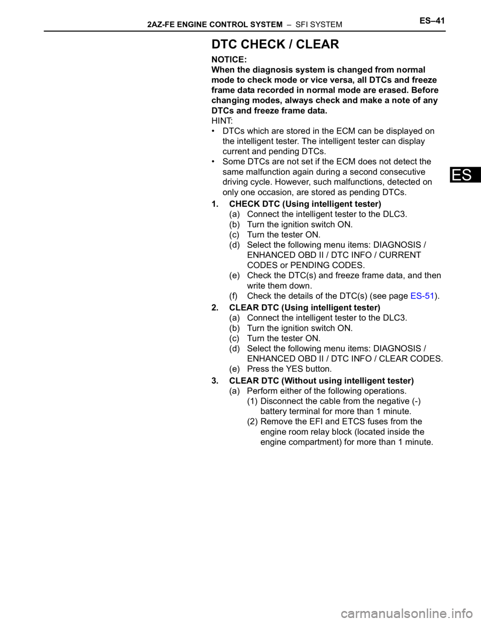
2AZ-FE ENGINE CONTROL SYSTEM – SFI SYSTEMES–41
ES
DTC CHECK / CLEAR
NOTICE:
When the diagnosis system is changed from normal
mode to check mode or vice versa, all DTCs and freeze
frame data recorded in normal mode are erased. Before
changing modes, always check and make a note of any
DTCs and freeze frame data.
HINT:
• DTCs which are stored in the ECM can be displayed on
the intelligent tester. The intelligent tester can display
current and pending DTCs.
• Some DTCs are not set if the ECM does not detect the
same malfunction again during a second consecutive
driving cycle. However, such malfunctions, detected on
only one occasion, are stored as pending DTCs.
1. CHECK DTC (Using intelligent tester)
(a) Connect the intelligent tester to the DLC3.
(b) Turn the ignition switch ON.
(c) Turn the tester ON.
(d) Select the following menu items: DIAGNOSIS /
ENHANCED OBD II / DTC INFO / CURRENT
CODES or PENDING CODES.
(e) Check the DTC(s) and freeze frame data, and then
write them down.
(f) Check the details of the DTC(s) (see page ES-51).
2. CLEAR DTC (Using intelligent tester)
(a) Connect the intelligent tester to the DLC3.
(b) Turn the ignition switch ON.
(c) Turn the tester ON.
(d) Select the following menu items: DIAGNOSIS /
ENHANCED OBD II / DTC INFO / CLEAR CODES.
(e) Press the YES button.
3. CLEAR DTC (Without using intelligent tester)
(a) Perform either of the following operations.
(1) Disconnect the cable from the negative (-)
battery terminal for more than 1 minute.
(2) Remove the EFI and ETCS fuses from the
engine room relay block (located inside the
engine compartment) for more than 1 minute.