current TOYOTA RAV4 2006 Service Service Manual
[x] Cancel search | Manufacturer: TOYOTA, Model Year: 2006, Model line: RAV4, Model: TOYOTA RAV4 2006Pages: 2000, PDF Size: 45.84 MB
Page 1556 of 2000
BRAKE CONTROL – VEHICLE STABILITY CONTROL SYSTEMBC–53
BC
FREEZE FRAME DATA
1. FREEZE FRAME DATA
HINT:
• Whenever a DTC is detected or the ABS operates,
the skid control ECU stores the current vehicle
(sensor) state as freeze frame data.
• The skid control ECU stores the number of times
(maximum: 31) the ignition switch has been turned
from OFF to ON since the last time the ABS was
activated. However, if the vehicle was stationary or
running at a low speed (7 km/h [4.3 mph] or less), or if
a DTC is detected, the skid control ECU stops
counting.
• Freeze frame data at the time the ABS operates:
The skid control ECU stores and updates the data
whenever the ABS system operates.
When the ECU stores data at the time a DTC is
detected, the data stored when the ABS operated is
erased.
• Freeze frame data at the time a DTC is detected:
When the skid control ECU stores data at the time a
DTC is detected, no updates will be performed until
the data is cleared.
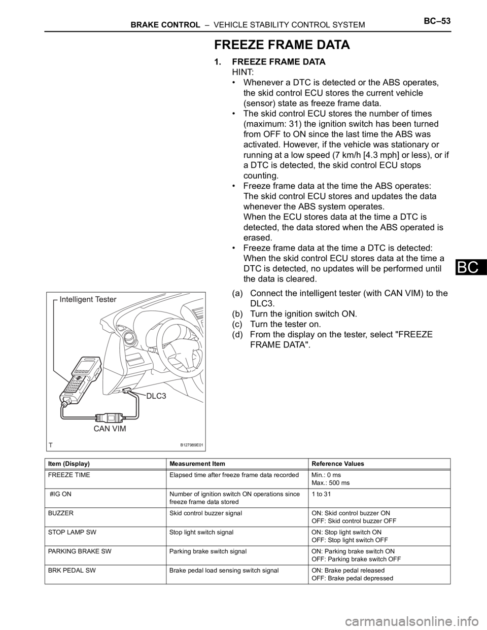
(a) Connect the intelligent tester (with CAN VIM) to the
DLC3.
(b) Turn the ignition switch ON.
(c) Turn the tester on.
(d) From the display on the tester, select "FREEZE
FRAME DATA".
B127989E01
Item (Display) Measurement Item Reference Values
FREEZE TIME Elapsed time after freeze frame data recorded Min.: 0 ms
Max.: 500 ms
#IG ON Number of ignition switch ON operations since
freeze frame data stored1 to 31
BUZZER Skid control buzzer signal ON: Skid control buzzer ON
OFF: Skid control buzzer OFF
STOP LAMP SW Stop light switch signal ON: Stop light switch ON
OFF: Stop light switch OFF
PARKING BRAKE SW Parking brake switch signal ON: Parking brake switch ON
OFF: Parking brake switch OFF
BRK PEDAL SW Brake pedal load sensing switch signal ON: Brake pedal released
OFF: Brake pedal depressed
Page 1614 of 2000
PS–14POWER STEERING – ELECTRONIC POWER STEERING SYSTEM
PS
FREEZE FRAME DATA
1. FREEZE FRAME DATA
NOTICE:
• It is difficult to show the specified values
(judgment values) clearly because freeze frame
data values change significantly due to
differences in measurement conditions,
surroundings, or vehicle conditions. For this
reason, there may be a problem even when the
values are within specifications.
• Turn the ignition switch ON and park the vehicle
on level ground. Check the freeze frame data by
using intelligent tester.
(a) Connect the intelligent tester (with CAN VIM) to the
DLC3.
(b) Turn the ignition switch ON and check the freeze
frame data by following the prompts on the
intelligent tester display.
Power steering ECU
Item Item Description: Range
(Display)Inspection Condition Reference Value
BATTERY VOLTAGE Battery voltage:
Min.: 0 V
Max.: 25.5 V- 10 to 14 V
SPD Vehicle speed from meter:
Min.: 0 km/h (0 mph)
Max.: 300 km/h (187.5 mph)Vehicle stopped 0 km/h (mph)
Vehicle driven at constant speedNo significant fluctuation
ENGINE REV Show the engine revolution:
Min.: 0 rpm
Max.: 12800 rpmEngine is running at a constant
speedNo significant fluctuation
MOTOR ACTUAL Amount of current to motor:
Min.: -327.68 A
Max.: 327.67 APower steering is in operationValue changes in proportion to
steering effort
COMMAND VALUE Demanded amount of current to
motor:
Min.: -327.68 A
Max.: 327.68 APower steering is in operationValue changes in proportion to
steering effort
STR ANGL VEL Steering angle speed:
Min.: -32768
/sec.
Max.: 32767/sec.Steering wheel is turned Value changes in proportion to
steering effort
STEERING TORQUE Steering wheel torque:
Min.: -7 Nm
Max.: 7 Nm--
THERMISTOR TEMP ECU substrate temperature:
Min.: -40
C
Max.: 150
CIgnition switch ON -
PIG SUPPLY Power source voltage to activate
motor:
Min.: 0 V
Max.: 20.1531 VPower steering in operation 10 to 14 V
IG SUPPLY ECU power source voltage:
Min.: 0 V
Max.: 20.1531 VIgnition switch ON 10 to 14 V
MOTOR ROTATE Motor rotation angle:
Min.: 0
Max.: 360
Power steering in operation During steering operation, motor
rotation angle value changes from
0 to 360
MOTOR VOLTAGE Motor power supply voltage:
0 V
Max.: 45.955 VPower steering in operation -
Page 1617 of 2000
POWER STEERING – ELECTRONIC POWER STEERING SYSTEMPS–17
PS
DATA LIST / ACTIVE TEST
1. READ DATA LIST
HINT:
Using the intelligent tester's DATA LIST allows switch,
sensor, actuator and other item values to be read without
removing any parts. Reading the DATA LIST early in
troubleshooting is one way to save time.
(a) Connect the intelligent tester (with CAN VIM) to the
DLC3.
(b) Turn the ignition switch ON and press the intelligent
tester main switch ON.
(c) Read the DATA LIST by following the directions on
the tester screen.
Tester Display Measurement Item/Range Normal Condition Reference Value
BATTERY VOLTAGE Battery voltage:
Min.: 0 V
Max.: 25.5 V- 10 to 14 V
SPD Vehicle speed from meter:
Min.: 0 km/h (0 mph)
Max.: 300 km/h (187.5 mph)Vehicle stopped 0 km/h (0 mph)
Vehicle driven at constant speed No significant fluctuation
SPD SIG INVALID Record of vehicle speed signal
invalid:
REC or UNREC- UNREC
ENGINE REV Show the engine revolution:
Min.: 0 rpm
Max.: 12800 rpmEngine is running at a constant
speedNo significant fluctuation
ENG REV INTER Record of engine revolution
signal interruption
REC or UNREC- UNREC
MOTOR ACTUAL Amount of current to motor:
Min.: -327.68 A
Max.: 327.67 APower steering is in operation Value changes in proportion to
steering effort
COMMAND VALUE Demanded amount of current to
motor:
Min.: -327.68 A
Max.: 327.68 APower steering is in operation Value changes in proportion to
steering effort
STR ANGL VEL Steering angle speed:
Min.: -32768
/sec.
Max.: 32767
/sec.Steering wheel is turned Value changes in proportion to
steering effort
STEERING TORQUE Steering wheel torque:
Min.: -7 Nm
Max.: 7 Nm--
THERMISTOR TEMP ECU substrate temperature:
Min.: -40
C
Max.: 150
CIgnition switch ON -
PIG SUPPLY Power source voltage to activate
motor:
Min.: 0 V
Max.: 20.1531 VPower steering in operation 10 to 14 V
IG SUPPLY ECU power source voltage:
Min.: 0 V
Max.: 20.1531 VIgnition switch ON 10 to 14 V
MTR OVERHEAT Continuous overheat prevention
control record:
REC or UNREC- UNREC
MTR LOW POWER PIG power source voltage drop
record:
REC or UNREC- UNREC
Page 1624 of 2000

PS–24POWER STEERING – ELECTRONIC POWER STEERING SYSTEM
PS
DESCRIPTION
The power steering ECU supplies current to the power steering motor through this circuit.
INSPECTION PROCEDURE
(a) Check for DTC.
OK:
DTC is not output.
OK
NG
DTC C1521/25 Short in Motor Circuit
DTC No. DTC Detection Condition Trouble Area
C1521/25 Motor over current Power steering ECU
1RECONFIRM DTC
PROCEED TO NEXT CIRCUIT INSPECTION
SHOWN IN PROBLEM SYMPTOMS TABLE
REPLACE POWER STEERING ECU
Page 1625 of 2000
POWER STEERING – ELECTRONIC POWER STEERING SYSTEMPS–25
PS
DESCRIPTION
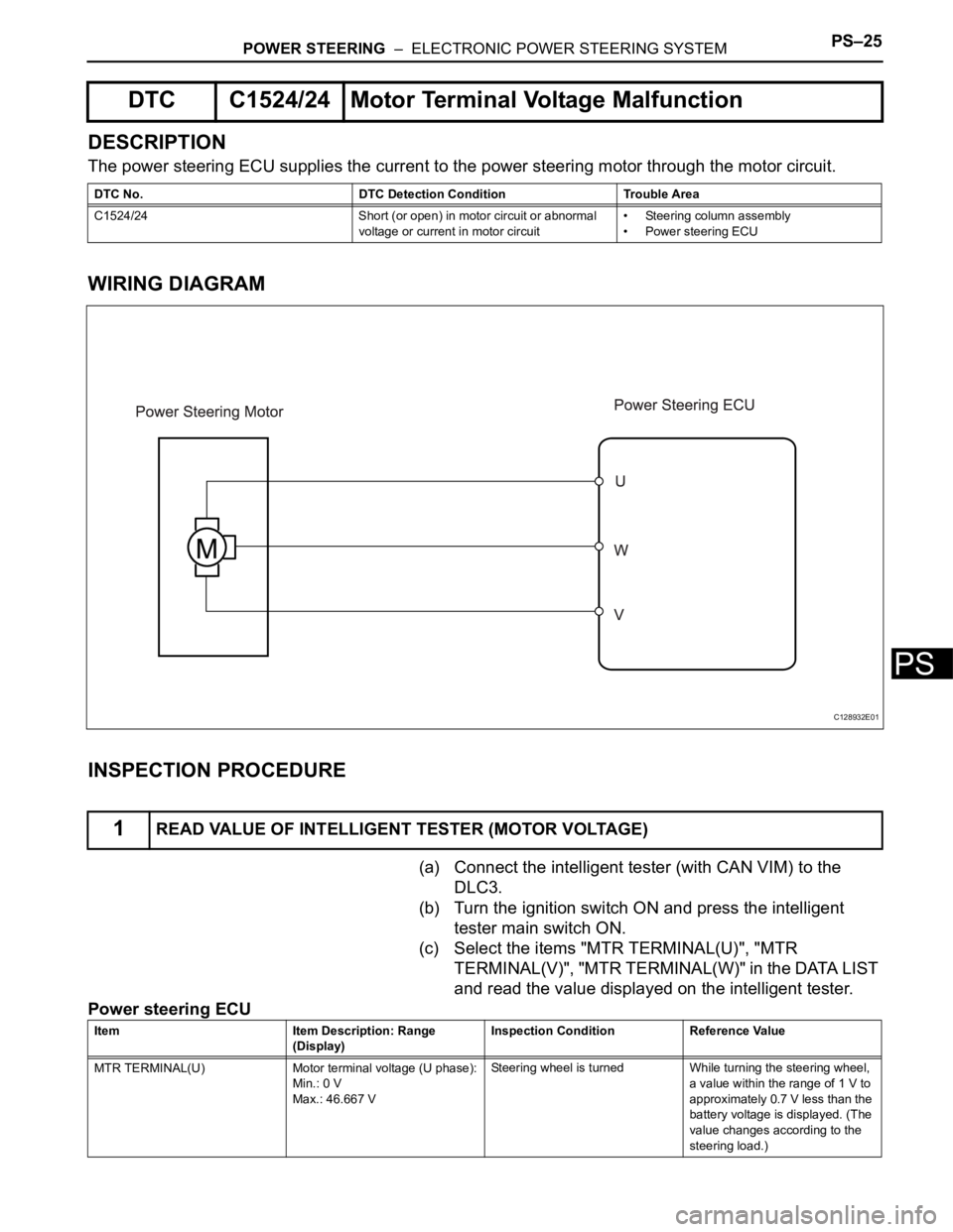
The power steering ECU supplies the current to the power steering motor through the motor circuit.
WIRING DIAGRAM
INSPECTION PROCEDURE
(a) Connect the intelligent tester (with CAN VIM) to the
DLC3.
(b) Turn the ignition switch ON and press the intelligent
tester main switch ON.
(c) Select the items "MTR TERMINAL(U)", "MTR
TERMINAL(V)", "MTR TERMINAL(W)" in the DATA LIST
and read the value displayed on the intelligent tester.
Power steering ECU
DTC C1524/24 Motor Terminal Voltage Malfunction
DTC No. DTC Detection Condition Trouble Area
C1524/24 Short (or open) in motor circuit or abnormal
voltage or current in motor circuit• Steering column assembly
• Power steering ECU
1READ VALUE OF INTELLIGENT TESTER (MOTOR VOLTAGE)
C128932E01
Item Item Description: Range
(Display)Inspection Condition Reference Value
MTR TERMINAL(U) Motor terminal voltage (U phase):
Min.: 0 V
Max.: 46.667 VSteering wheel is turned While turning the steering wheel,
a value within the range of 1 V to
approximately 0.7 V less than the
battery voltage is displayed. (The
value changes according to the
steering load.)
Page 1638 of 2000
AC–10AIR CONDITIONING – AIR CONDITIONING SYSTEM (for Automatic Air Conditioning Sys-
tem)
AC
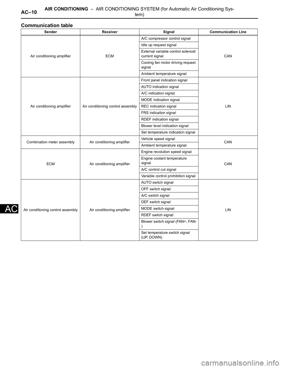
Communication table
Sender Receiver Signal Communication Line
Air conditioning amplifier ECMA/C compressor control signal
CAN Idle up request signal
External variable control solenoid
current signal
Cooling fan motor driving request
signal
Ambient temperature signal
Air conditioning amplifier Air conditioning control assemblyFront panel indication signal
LIN AUTO indication signal
A/C indication signal
MODE indication signal
REC indication signal
FRS indication signal
RDEF indication signal
Blower level indication signal
Set temperature indication signal
Combination meter assembly Air conditioning amplifierVehicle speed signal
CAN
Ambient temperature signal
ECM Air conditioning amplifierEngine revolution speed signal
CAN Engine coolant temperature
signal
A/C control cut signal
Variable control prohibition signal
Air conditioning control assembly Air conditioning amplifierAUTO switch signal
LIN OFF switch signal
A/C switch signal
DEF switch signal
MODE switch signal
RDEF switch signal
Blower switch signal (FAN+, FAN-
)
Set temperature switch signal
(UP, DOWN)
Page 1640 of 2000
AC–12AIR CONDITIONING – AIR CONDITIONING SYSTEM (for Automatic Air Conditioning Sys-
tem)
AC
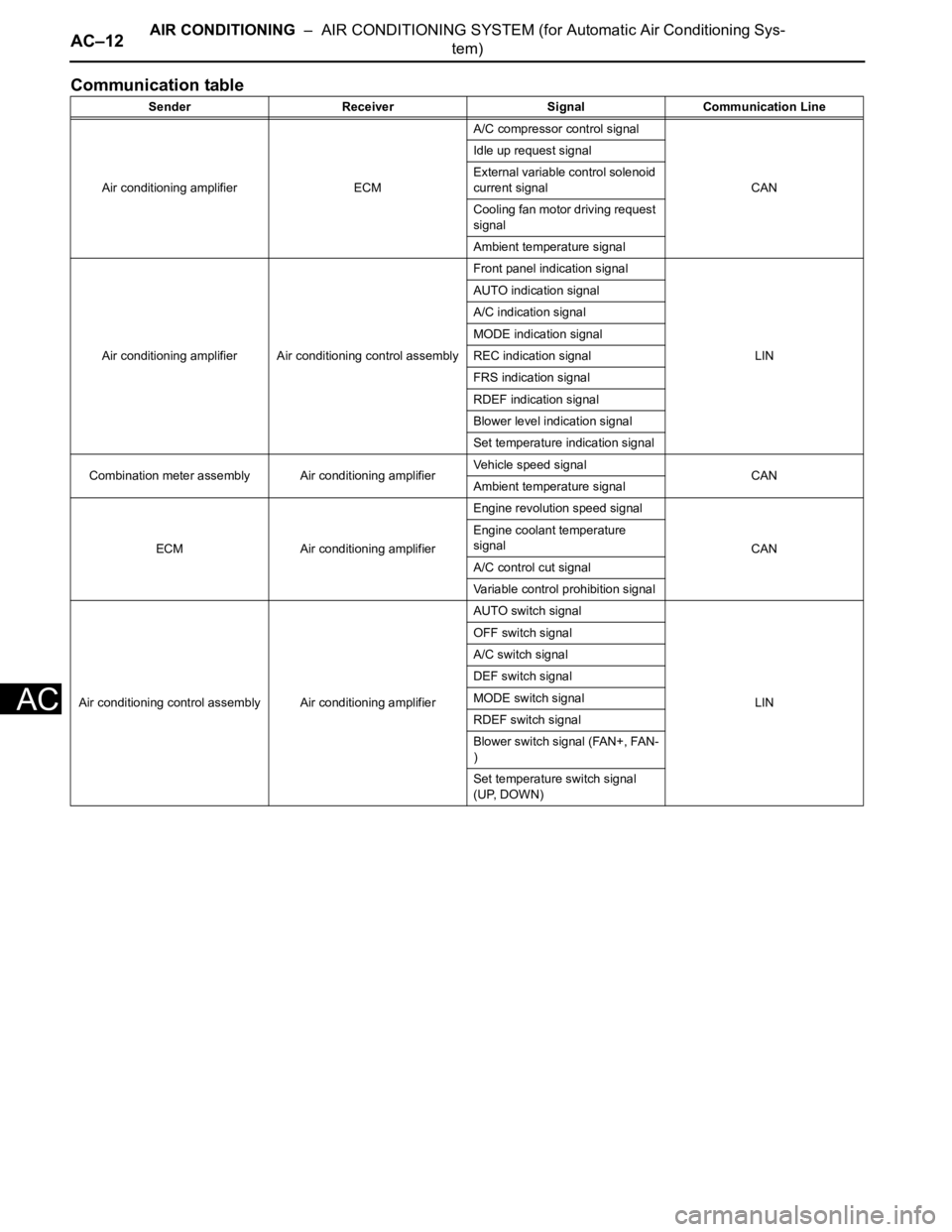
Communication table
Sender Receiver Signal Communication Line
Air conditioning amplifier ECMA/C compressor control signal
CAN Idle up request signal
External variable control solenoid
current signal
Cooling fan motor driving request
signal
Ambient temperature signal
Air conditioning amplifier Air conditioning control assemblyFront panel indication signal
LIN AUTO indication signal
A/C indication signal
MODE indication signal
REC indication signal
FRS indication signal
RDEF indication signal
Blower level indication signal
Set temperature indication signal
Combination meter assembly Air conditioning amplifierVehicle speed signal
CAN
Ambient temperature signal
ECM Air conditioning amplifierEngine revolution speed signal
CAN Engine coolant temperature
signal
A/C control cut signal
Variable control prohibition signal
Air conditioning control assembly Air conditioning amplifierAUTO switch signal
LIN OFF switch signal
A/C switch signal
DEF switch signal
MODE switch signal
RDEF switch signal
Blower switch signal (FAN+, FAN-
)
Set temperature switch signal
(UP, DOWN)
Page 1649 of 2000
AIR CONDITIONING – AIR CONDITIONING SYSTEM (for Automatic Air Conditioning Sys-
tem)AC–21
AC
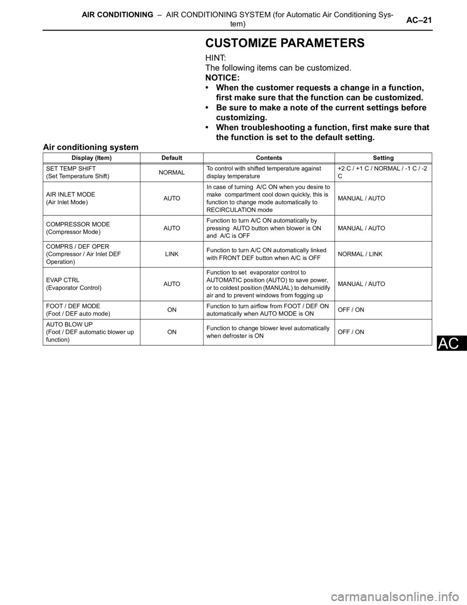
CUSTOMIZE PARAMETERS
HINT:
The following items can be customized.
NOTICE:
• When the customer requests a change in a function,
first make sure that the function can be customized.
• Be sure to make a note of the current settings before
customizing.
• When troubleshooting a function, first make sure that
the function is set to the default setting.
Air conditioning system
Display (Item) Default Contents Setting
SET TEMP SHIFT
(Set Temperature Shift)NORMALTo control with shifted temperature against
display temperature+2 C / +1 C / NORMAL / -1 C / -2
C
AIR INLET MODE
(Air Inlet Mode)AUTOIn case of turning A/C ON when you desire to
make compartment cool down quickly, this is
function to change mode automatically to
RECIRCULATION modeMANUAL / AUTO
COMPRESSOR MODE
(Compressor Mode)AUTOFunction to turn A/C ON automatically by
pressing AUTO button when blower is ON
and A/C is OFFMANUAL / AUTO
COMPRS / DEF OPER
(Compressor / Air Inlet DEF
Operation)LINKFunction to turn A/C ON automatically linked
with FRONT DEF button when A/C is OFFNORMAL / LINK
EVAP CTRL
(Evaporator Control)AUTOFunction to set evaporator control to
AUTOMATIC position (AUTO) to save power,
or to coldest position (MANUAL) to dehumidify
air and to prevent windows from fogging upMANUAL / AUTO
FOOT / DEF MODE
(Foot / DEF auto mode)ONFunction to turn airflow from FOOT / DEF ON
automatically when AUTO MODE is ONOFF / ON
AUTO BLOW UP
(Foot / DEF automatic blower up
function)ONFunction to change blower level automatically
when defroster is ONOFF / ON
Page 1677 of 2000
RS–28SUPPLEMENTAL RESTRAINT SYSTEM – AIRBAG SYSTEM
RS
(e) SRS WARNING LIGHT
(1) The SRS warning light is located on the telltale
light. It comes on to inform the driver of system
trouble when a malfunction is detected in the
self-diagnosis of the center airbag sensor. Under
normal operating conditions when the ignition
switch is turned on, it comes on for
approximately 6 seconds and then goes off.
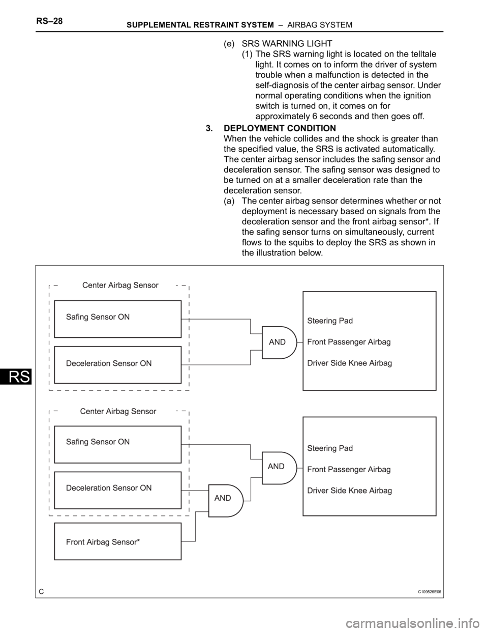
3. DEPLOYMENT CONDITION
When the vehicle collides and the shock is greater than
the specified value, the SRS is activated automatically.
The center airbag sensor includes the safing sensor and
deceleration sensor. The safing sensor was designed to
be turned on at a smaller deceleration rate than the
deceleration sensor.
(a) The center airbag sensor determines whether or not
deployment is necessary based on signals from the
deceleration sensor and the front airbag sensor*. If
the safing sensor turns on simultaneously, current
flows to the squibs to deploy the SRS as shown in
the illustration below.
C109526E06
Page 1678 of 2000
SUPPLEMENTAL RESTRAINT SYSTEM – AIRBAG SYSTEMRS–29
RS
HINT:
* : In case of a frontal collision, the ignition signal
could be output with the deceleration sensor ON
signal even without a signal from the front airbag
sensor.
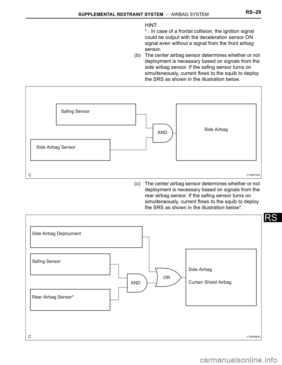
(b) The center airbag sensor determines whether or not
deployment is necessary based on signals from the
side airbag sensor. If the safing sensor turns on
simultaneously, current flows to the squib to deploy
the SRS as shown in the illustration below.
(c) The center airbag sensor determines whether or not
deployment is necessary based on signals from the
rear airbag sensor. If the safing sensor turns on
simultaneously, current flows to the squib to deploy
the SRS as shown in the illustration below*.
C109527E06
C109528E06