TOYOTA RAV4 2006 Service Repair Manual
Manufacturer: TOYOTA, Model Year: 2006, Model line: RAV4, Model: TOYOTA RAV4 2006Pages: 2000, PDF Size: 45.84 MB
Page 201 of 2000
EM–262GR-FE ENGINE MECHANICAL – ENGINE ASSEMBLY
EM
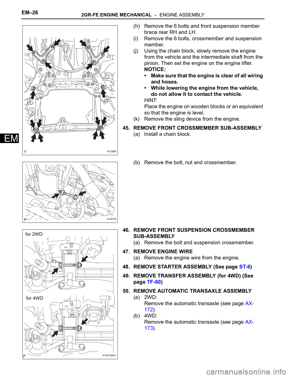
(h) Remove the 6 bolts and front suspension member
brace rear RH and LH.
(i) Remove the 6 bolts, crossmember and suspension
member.
(j) Using the chain block, slowly remove the engine
from the vehicle and the intermediate shaft from the
pinion. Then set the engine on the engine lifter.
NOTICE:
• Make sure that the engine is clear of all wiring
and hoses.
• While lowering the engine from the vehicle,
do not allow it to contact the vehicle.
HINT:
Place the engine on wooden blocks or an equivalent
so that the engine is level.
(k) Remove the sling device from the engine.
45. REMOVE FRONT CROSSMEMBER SUB-ASSEMBLY
(a) Install a chain block.
(b) Remove the bolt, nut and crossmember.
46. REMOVE FRONT SUSPENSION CROSSMEMBER
SUB-ASSEMBLY
(a) Remove the bolt and suspension crossmember.
47. REMOVE ENGINE WIRE
(a) Remove the engine wire from the engine.
48. REMOVE STARTER ASSEMBLY (See page ST-6)
49. REMOVE TRANSFER ASSEMBLY (for 4WD) (See
page TF-60)
50. REMOVE AUTOMATIC TRANSAXLE ASSEMBLY
(a) 2WD:
Remove the automatic transaxle (see page AX-
172).
(b) 4WD:
Remove the automatic transaxle (see page AX-
173).
A123580
A139135
A139136E01
Page 202 of 2000
2GR-FE ENGINE MECHANICAL – ENGINE ASSEMBLYEM–27
EM
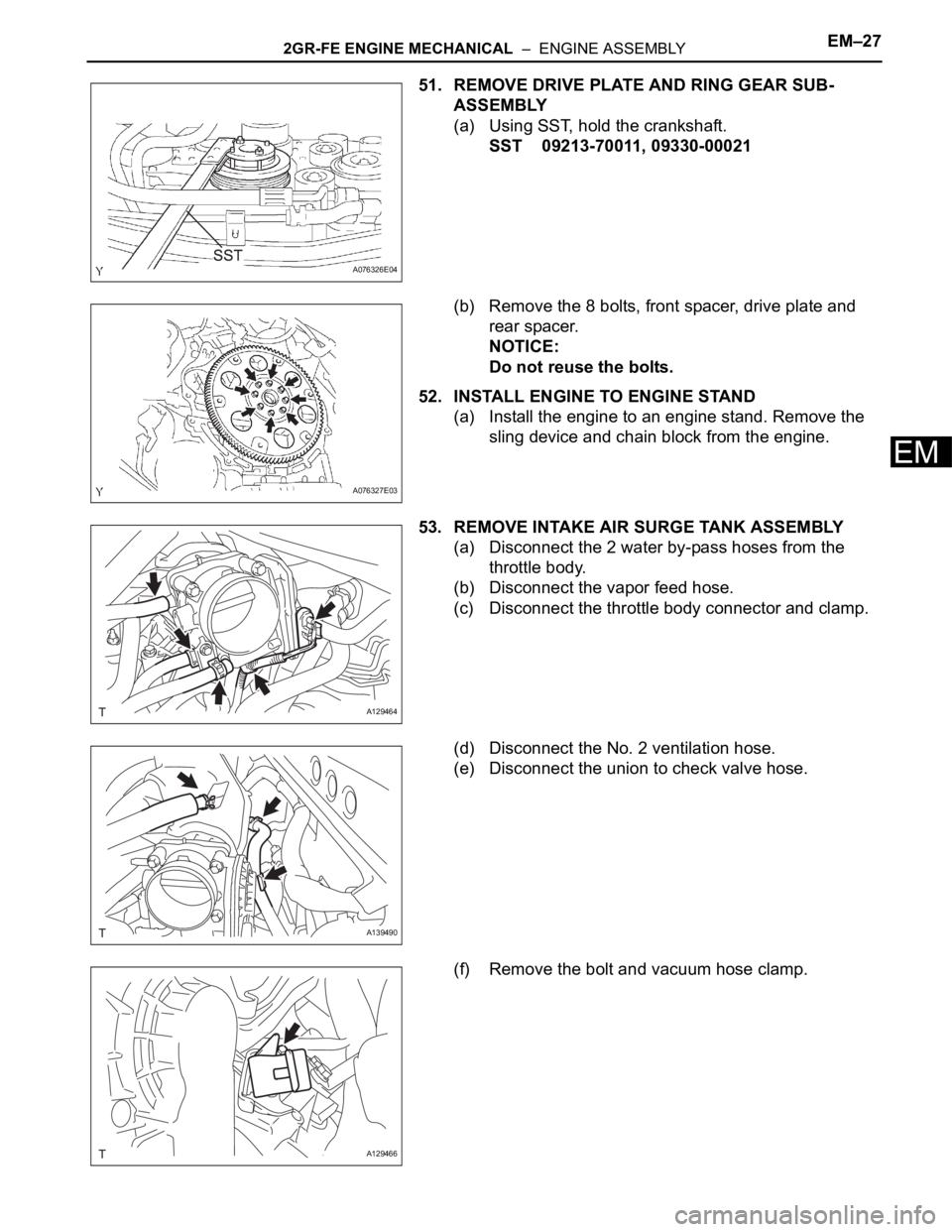
51. REMOVE DRIVE PLATE AND RING GEAR SUB-
ASSEMBLY
(a) Using SST, hold the crankshaft.
SST 09213-70011, 09330-00021
(b) Remove the 8 bolts, front spacer, drive plate and
rear spacer.
NOTICE:
Do not reuse the bolts.
52. INSTALL ENGINE TO ENGINE STAND
(a) Install the engine to an engine stand. Remove the
sling device and chain block from the engine.
53. REMOVE INTAKE AIR SURGE TANK ASSEMBLY
(a) Disconnect the 2 water by-pass hoses from the
throttle body.
(b) Disconnect the vapor feed hose.
(c) Disconnect the throttle body connector and clamp.
(d) Disconnect the No. 2 ventilation hose.
(e) Disconnect the union to check valve hose.
(f) Remove the bolt and vacuum hose clamp.
A076326E04
A076327E03
A129464
A139490
A129466
Page 203 of 2000
EM–282GR-FE ENGINE MECHANICAL – ENGINE ASSEMBLY
EM
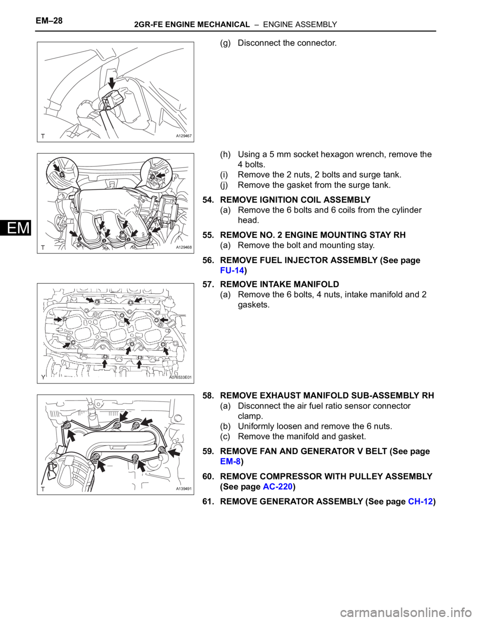
(g) Disconnect the connector.
(h) Using a 5 mm socket hexagon wrench, remove the
4 bolts.
(i) Remove the 2 nuts, 2 bolts and surge tank.
(j) Remove the gasket from the surge tank.
54. REMOVE IGNITION COIL ASSEMBLY
(a) Remove the 6 bolts and 6 coils from the cylinder
head.
55. REMOVE NO. 2 ENGINE MOUNTING STAY RH
(a) Remove the bolt and mounting stay.
56. REMOVE FUEL INJECTOR ASSEMBLY (See page
FU-14)
57. REMOVE INTAKE MANIFOLD
(a) Remove the 6 bolts, 4 nuts, intake manifold and 2
gaskets.
58. REMOVE EXHAUST MANIFOLD SUB-ASSEMBLY RH
(a) Disconnect the air fuel ratio sensor connector
clamp.
(b) Uniformly loosen and remove the 6 nuts.
(c) Remove the manifold and gasket.
59. REMOVE FAN AND GENERATOR V BELT (See page
EM-8)
60. REMOVE COMPRESSOR WITH PULLEY ASSEMBLY
(See page AC-220)
61. REMOVE GENERATOR ASSEMBLY (See page CH-12)
A129467
A129468
A076533E01
A139491
Page 204 of 2000
2GR-FE ENGINE MECHANICAL – ENGINE ASSEMBLYEM–29
EM
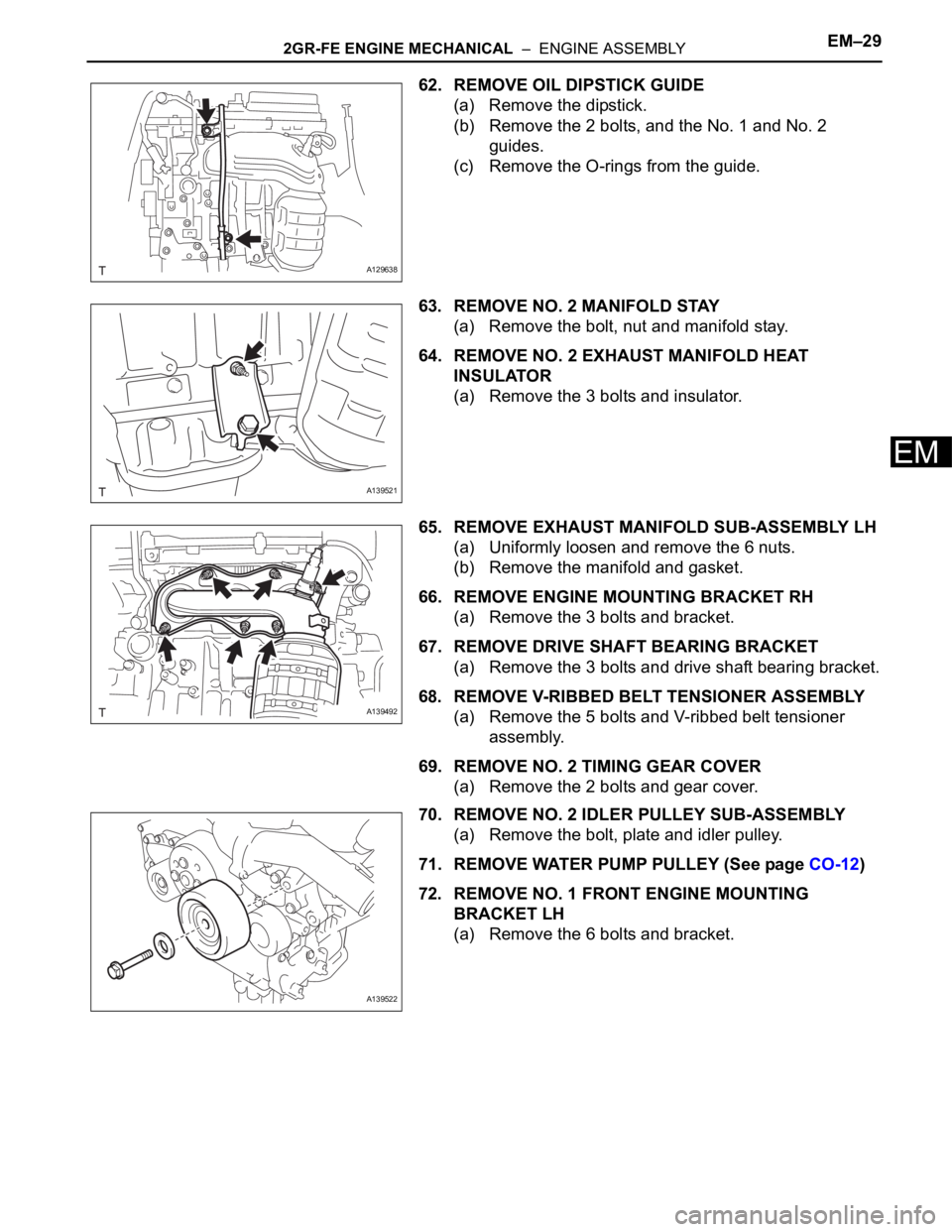
62. REMOVE OIL DIPSTICK GUIDE
(a) Remove the dipstick.
(b) Remove the 2 bolts, and the No. 1 and No. 2
guides.
(c) Remove the O-rings from the guide.
63. REMOVE NO. 2 MANIFOLD STAY
(a) Remove the bolt, nut and manifold stay.
64. REMOVE NO. 2 EXHAUST MANIFOLD HEAT
INSULATOR
(a) Remove the 3 bolts and insulator.
65. REMOVE EXHAUST MANIFOLD SUB-ASSEMBLY LH
(a) Uniformly loosen and remove the 6 nuts.
(b) Remove the manifold and gasket.
66. REMOVE ENGINE MOUNTING BRACKET RH
(a) Remove the 3 bolts and bracket.
67. REMOVE DRIVE SHAFT BEARING BRACKET
(a) Remove the 3 bolts and drive shaft bearing bracket.
68. REMOVE V-RIBBED BELT TENSIONER ASSEMBLY
(a) Remove the 5 bolts and V-ribbed belt tensioner
assembly.
69. REMOVE NO. 2 TIMING GEAR COVER
(a) Remove the 2 bolts and gear cover.
70. REMOVE NO. 2 IDLER PULLEY SUB-ASSEMBLY
(a) Remove the bolt, plate and idler pulley.
71. REMOVE WATER PUMP PULLEY (See page CO-12)
72. REMOVE NO. 1 FRONT ENGINE MOUNTING
BRACKET LH
(a) Remove the 6 bolts and bracket.
A129638
A139521
A139492
A139522
Page 205 of 2000
EM–302GR-FE ENGINE MECHANICAL – ENGINE ASSEMBLY
EM
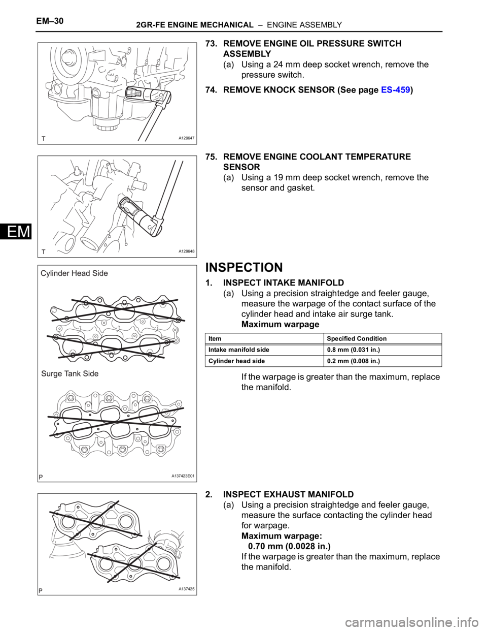
73. REMOVE ENGINE OIL PRESSURE SWITCH
ASSEMBLY
(a) Using a 24 mm deep socket wrench, remove the
pressure switch.
74. REMOVE KNOCK SENSOR (See page ES-459)
75. REMOVE ENGINE COOLANT TEMPERATURE
SENSOR
(a) Using a 19 mm deep socket wrench, remove the
sensor and gasket.
INSPECTION
1. INSPECT INTAKE MANIFOLD
(a) Using a precision straightedge and feeler gauge,
measure the warpage of the contact surface of the
cylinder head and intake air surge tank.
Maximum warpage
If the warpage is greater than the maximum, replace
the manifold.
2. INSPECT EXHAUST MANIFOLD
(a) Using a precision straightedge and feeler gauge,
measure the surface contacting the cylinder head
for warpage.
Maximum warpage:
0.70 mm (0.0028 in.)
If the warpage is greater than the maximum, replace
the manifold.
A129647
A129648
A137423E01
Item Specified Condition
Intake manifold side 0.8 mm (0.031 in.)
Cylinder head side 0.2 mm (0.008 in.)
A137425
Page 206 of 2000
FU–42AZ-FE FUEL – FUEL SYSTEM
FU
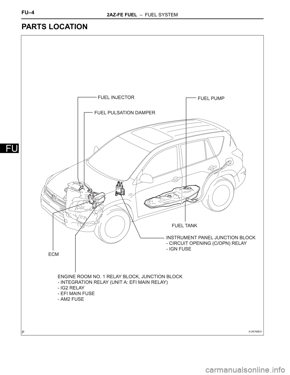
PARTS LOCATION
A126790E01
Page 207 of 2000
2AZ-FE FUEL – FUEL SYSTEMFU–5
FU
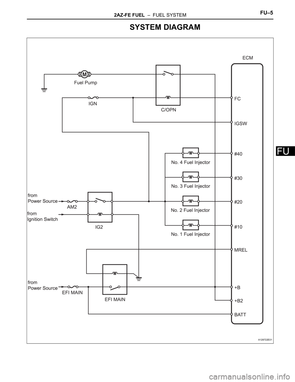
SYSTEM DIAGRAM
A128722E01
Page 208 of 2000
FU–62AZ-FE FUEL – FUEL SYSTEM
FU
ON-VEHICLE INSPECTION
1. CHECK FUEL PUMP OPERATION
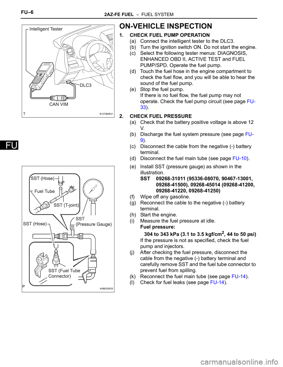
(a) Connect the intelligent tester to the DLC3.
(b) Turn the ignition switch ON. Do not start the engine.
(c) Select the following tester menus: DIAGNOSIS,
ENHANCED OBD II, ACTIVE TEST and FUEL
PUMP/SPD. Operate the fuel pump.
(d) Touch the fuel hose in the engine compartment to
check the fuel flow, and you will be able to hear the
sound of the fuel pump.
(e) Stop the fuel pump.
If there is no fuel flow, the fuel pump may not
operate. Check the fuel pump circuit (see page FU-
33).
2. CHECK FUEL PRESSURE
(a) Check that the battery positive voltage is above 12
V.
(b) Discharge the fuel system pressure (see page FU-
9).
(c) Disconnect the cable from the negative (-) battery
terminal.
(d) Disconnect the fuel main tube (see page FU-10).
(e) Install SST (pressure gauge) as shown in the
illustration.
SST 09268-31011 (95336-08070, 90467-13001,
09268-41500), 09268-45014 (09268-41200,
09268-41220, 09268-41250)
(f) Wipe off any gasoline.
(g) Reconnect the cable to the negative (-) battery
terminal.
(h) Start the engine.
(i) Measure the fuel pressure at idle.
Fuel pressure:
304 to 343 kPa (3.1 to 3.5 kgf/cm
2, 44 to 50 psi)
If the pressure is not as specified, check the fuel
pump and injectors.
(j) After checking the fuel pressure, disconnect the
cable from the negative (-) battery terminal and
carefully remove SST and the fuel tube connector to
prevent fuel from spilling.
(k) Reconnect the fuel main tube (see page FU-14).
(l) Check for fuel leaks (see page FU-14).
B127989E01
A088229E05
Page 209 of 2000

IN–26INTRODUCTION – REPAIR INSTRUCTION
IN
CUSTOMIZE PARAMETERS
NOTICE:
• When the customer requests a change in a function,
first make sure that the function can be customized.
• Make a note of the current settings before
customizing.
• When troubleshooting a function, first make sure that
the function is set to the default setting.
1. Combination meter
2. Air conditioning system
3. Power Door Lock Control System
4. Wireless Door Lock Control System
Display (Item) Default Function Setting
SEAT BELT WARN D/P ON Seat belt warning buzzer ON /
OFF settingD/P ON: Driver and passenger
buzzer ON
D ON: Driver buzzer ON
P ON: Passenger buzzer ON
D/P OFF: Driver and passenger
buzzer OFF
Display (Item) Default Contents Setting
SET TEMP SHIFT
(Set Temperature Shift)NORMALTo control with shifted temperature against
display temperature+2 C / +1 C / NORMAL / -1 C / -2
C
AIR INLET MODE
(Air Inlet Mode)AUTOIn case of turning A/C ON when you desire to
make compartment cool down quickly, this is
function to change mode automatically to
RECIRCULATION modeMANUAL / AUTO
COMPRESSOR MODE
(Compressor Mode)AUTOFunction to turn A/C ON automatically by
pressing AUTO button when blower is ON
and A/C is OFFMANUAL / AUTO
COMPRS / DEF OPER
(Compressor / Air Inlet DEF
Operation)LINKFunction to turn A/C ON automatically linked
with FRONT DEF button when A/C is OFFNORMAL / LINK
EVAP CTRL
(Evaporator Control)AUTOFunction to set evaporator control to
AUTOMATIC position (AUTO) to save power,
or to coldest position (MANUAL) to dehumidify
air and to prevent windows from fogging upMANUAL / AUTO
FOOT / DEF MODE
(Foot / DEF auto mode)ONFunction to turn airflow from FOOT / DEF ON
automatically when AUTO MODE is ONOFF / ON
AUTO BLOW UP
(Foot / DEF automatic blower up
function)ONFunction to change blower level automatically
when defroster is ONOFF / ON
Display (Item) Default Function Setting
UNLK/KEY TWICE ON Unlocks only driver side door
when driver side door key
cylinder turned to unlock once,
and unlocks all doors when
turned to unlock twice. For OFF
setting, turning it once unlocks all
doors.ON / OFF
Display (Item) Default Contents Setting
HAZARD ANS BACK ONWhen LOCK switch on
transmitter pressed, all hazard
warning lights illuminate once.
When UNLOCK switch pressed,
all hazard warning lights
illuminate twiceON / OFF
Page 210 of 2000

INTRODUCTION – REPAIR INSTRUCTIONIN–27
IN
5. Lighting System
WIRLS BUZZ OPER ONFunction that makes wireless
buzzer sound for answer-back
when transmitter LOCK /
UNLOCK switch pressedON / OFF
OPEN DOOR WARN ONIf door is not completely closed
and transmitter LOCK switch is
pressed, this function sounds a
buzzer for 10 secondsON / OFF
WIRELESS OPER ONON / OFF of wireless door lock
functionON / OFF
ALARM FUNCTION ONOperates security alarm when
PANIC switch on transmitter
continuously pressed for 1
secondON / OFF
UNLOCK / 2 OPER ONFunction that unlocks driver side
door when unlock switch on
transmitter is pressed once, and
unlocks all doors when pressed
twice. If setting is OFF, pressing
unlock switch once makes all
doors unlock.ON / OFF
AUTO LOCK DELAY 30sThis function controls amount of
time from unlocking doors to
automatic re-locking function30s / 60s Display (Item) Default Contents Setting
Display (Item) Default Contents Setting
LIGHTING TIME
(Lighting Time)15 secondsChanges illumination duration
after door closure.
(It will quickly fade out in case of
turning ignition switch ON.)7.5/15/30 (seconds)
I/L ON /ACC OFF
(Room light illuminates when
ignition switch turned OFF)ONIlluminates light when ignition
switch turned to ACC.
(Room light illuminated when
interior light switch in DOOR
position)ON / OFF
I/L ON / UNLOCK
(Room light illuminates when
door key unlocked.)ONFunction to light up room light
when unlocking with door key
cylinder.
(Room light illuminated when
interior light switch in DOOR
position)ON / OFF
LIGHT CONTROL ONFunction to light up foot light
when ignition switch is ON and
shift position is not P.ON / OFF