TOYOTA RAV4 2006 Service Repair Manual
Manufacturer: TOYOTA, Model Year: 2006,
Model line: RAV4,
Model: TOYOTA RAV4 2006
Pages: 2000, PDF Size: 45.84 MB
TOYOTA RAV4 2006 Service Repair Manual
RAV4 2006
TOYOTA
TOYOTA
https://www.carmanualsonline.info/img/14/57463/w960_57463-0.png
TOYOTA RAV4 2006 Service Repair Manual
Trending: tie rod, battery, tire, fuel type, oil filter, Install intake manifold, wiper blades
Page 181 of 2000
SERVICE SPECIFICATIONS – DIFFERENTIALSS–75
SS
TORQUE SPECIFICATIONS
Differential
Part Tightened N*m kgf*cm ft.*lbf
Rear differential No. 2 support x
Rear suspension member86 877 63
Rear differential support x Rear
suspension member140 1,428 103
Rear differential No. 2 support x
Rear differential
Rear differential No. 1 support x
Rear differential55 561 41
Rear differential support x Rear
differential98 999 72
Drain plug x Differential carrier
Filler plug x Differential carrier39 398 29
Electromagnetic coupling x Stud
bolt8.0 82 71 in.*lbf
Electromagnetic coupling x
Differential carrier19.6 200 14
Yoke x Differential carrier 5.0 51 44 in.*lbf
Drive pinion nut x Differential
drive pinion245 or less 2,498 or less 181 or less
Differential side bearing retainer x
Differential carrier34.3 350 25
Differential carrier x Differential
breather plug oil deflector5.0 51 44 in.*lbf
Differential ring gear x Differential
case90 918 66
Page 182 of 2000
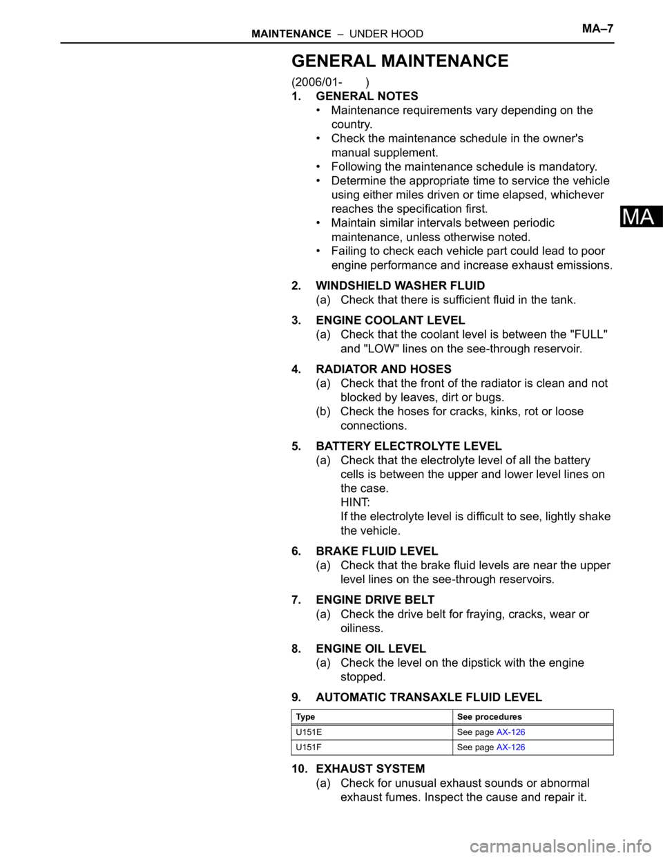
MAINTENANCE – UNDER HOODMA–7
MA
GENERAL MAINTENANCE
(2006/01- )
1. GENERAL NOTES
• Maintenance requirements vary depending on the
country.
• Check the maintenance schedule in the owner's
manual supplement.
• Following the maintenance schedule is mandatory.
• Determine the appropriate time to service the vehicle
using either miles driven or time elapsed, whichever
reaches the specification first.
• Maintain similar intervals between periodic
maintenance, unless otherwise noted.
• Failing to check each vehicle part could lead to poor
engine performance and increase exhaust emissions.
2. WINDSHIELD WASHER FLUID
(a) Check that there is sufficient fluid in the tank.
3. ENGINE COOLANT LEVEL
(a) Check that the coolant level is between the "FULL"
and "LOW" lines on the see-through reservoir.
4. RADIATOR AND HOSES
(a) Check that the front of the radiator is clean and not
blocked by leaves, dirt or bugs.
(b) Check the hoses for cracks, kinks, rot or loose
connections.
5. BATTERY ELECTROLYTE LEVEL
(a) Check that the electrolyte level of all the battery
cells is between the upper and lower level lines on
the case.
HINT:
If the electrolyte level is difficult to see, lightly shake
the vehicle.
6. BRAKE FLUID LEVEL
(a) Check that the brake fluid levels are near the upper
level lines on the see-through reservoirs.
7. ENGINE DRIVE BELT
(a) Check the drive belt for fraying, cracks, wear or
oiliness.
8. ENGINE OIL LEVEL
(a) Check the level on the dipstick with the engine
stopped.
9. AUTOMATIC TRANSAXLE FLUID LEVEL
10. EXHAUST SYSTEM
(a) Check for unusual exhaust sounds or abnormal
exhaust fumes. Inspect the cause and repair it.
Type See procedures
U151E See page AX-126
U151F See page AX-126
Page 183 of 2000
2AZ-FE ENGINE CONTROL SYSTEM – SFI SYSTEMES–3
ES
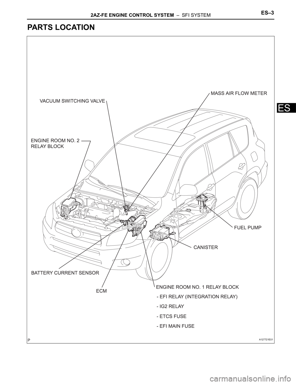
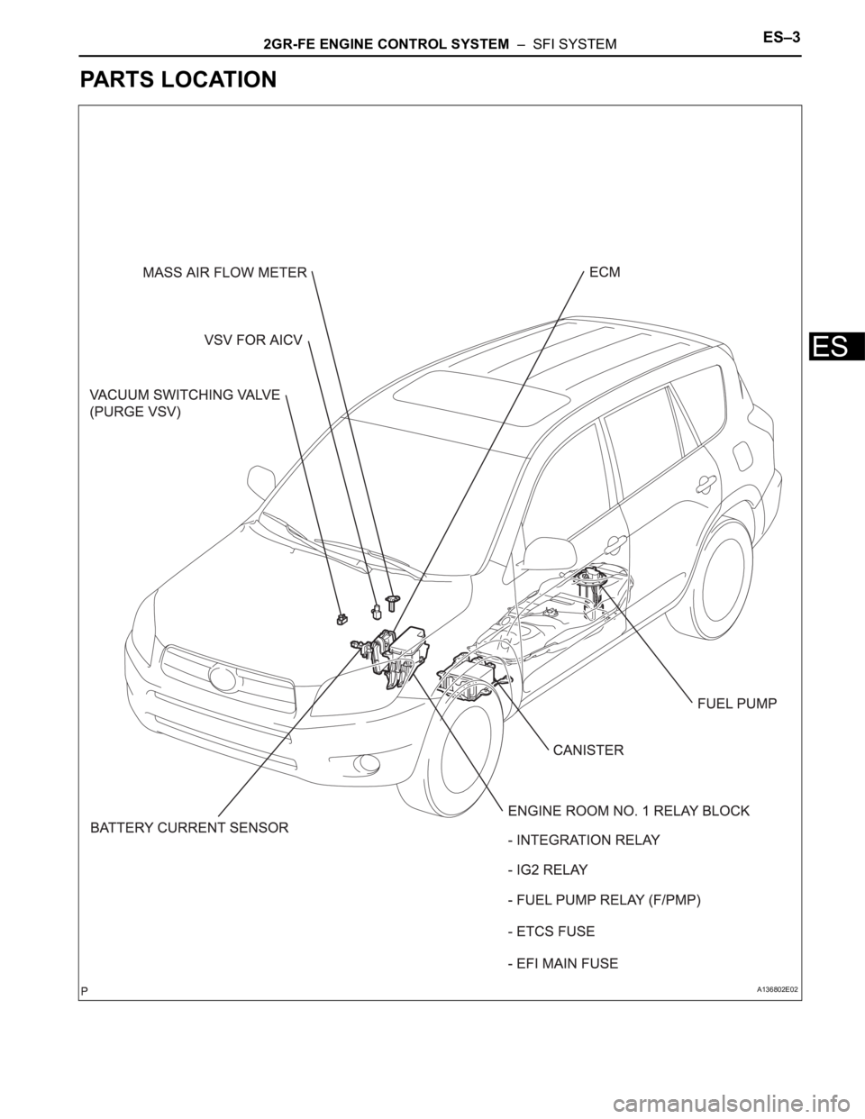
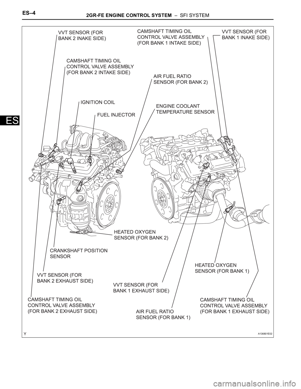
PARTS LOCATION
A127721E01
Page 184 of 2000
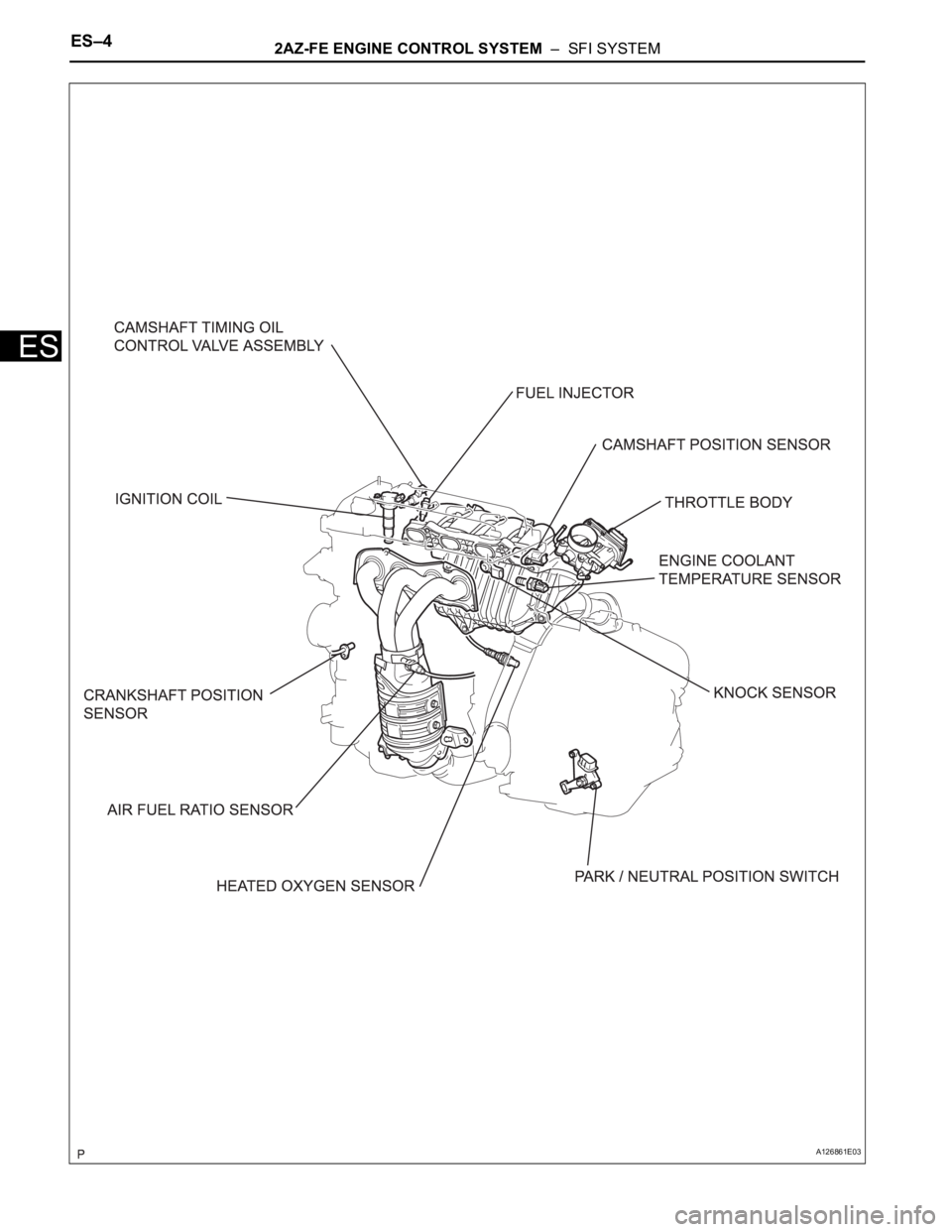
ES–42AZ-FE ENGINE CONTROL SYSTEM – SFI SYSTEM
ES
A126861E03
Page 185 of 2000
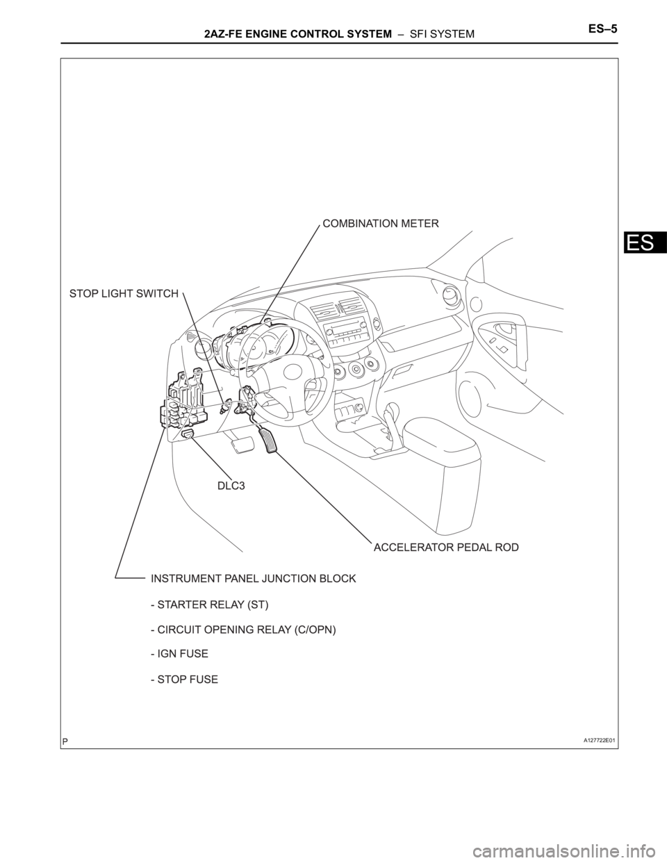
2AZ-FE ENGINE CONTROL SYSTEM – SFI SYSTEMES–5
ES
A127722E01
Page 186 of 2000
2AZ-FE ENGINE CONTROL SYSTEM – ECMES–429
ES
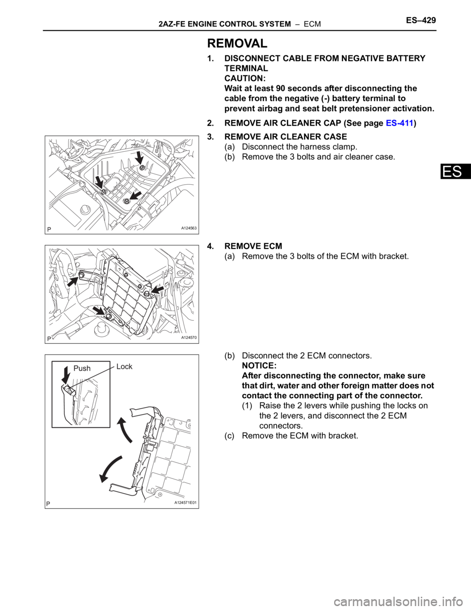
REMOVAL
1. DISCONNECT CABLE FROM NEGATIVE BATTERY
TERMINAL
CAUTION:
Wait at least 90 seconds after disconnecting the
cable from the negative (-) battery terminal to
prevent airbag and seat belt pretensioner activation.
2. REMOVE AIR CLEANER CAP (See page ES-411)
3. REMOVE AIR CLEANER CASE
(a) Disconnect the harness clamp.
(b) Remove the 3 bolts and air cleaner case.
4. REMOVE ECM
(a) Remove the 3 bolts of the ECM with bracket.
(b) Disconnect the 2 ECM connectors.
NOTICE:
After disconnecting the connector, make sure
that dirt, water and other foreign matter does not
contact the connecting part of the connector.
(1) Raise the 2 levers while pushing the locks on
the 2 levers, and disconnect the 2 ECM
connectors.
(c) Remove the ECM with bracket.
A124563
A124570
A124571E01
Page 187 of 2000
ES–4302AZ-FE ENGINE CONTROL SYSTEM – ECM
ES
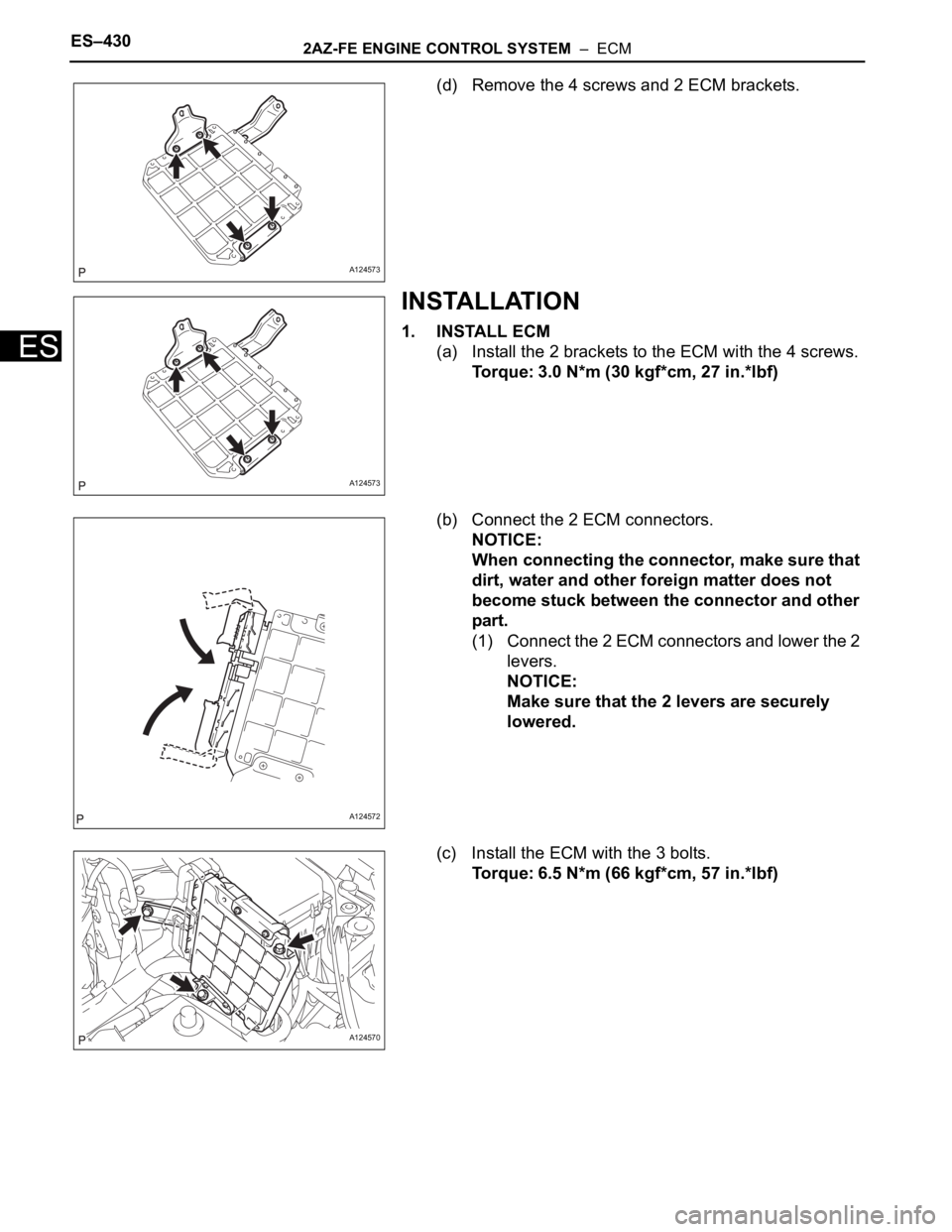
(d) Remove the 4 screws and 2 ECM brackets.
INSTALLATION
1. INSTALL ECM
(a) Install the 2 brackets to the ECM with the 4 screws.
Torque: 3.0 N*m (30 kgf*cm, 27 in.*lbf)
(b) Connect the 2 ECM connectors.
NOTICE:
When connecting the connector, make sure that
dirt, water and other foreign matter does not
become stuck between the connector and other
part.
(1) Connect the 2 ECM connectors and lower the 2
levers.
NOTICE:
Make sure that the 2 levers are securely
lowered.
(c) Install the ECM with the 3 bolts.
Torque: 6.5 N*m (66 kgf*cm, 57 in.*lbf)
A124573
A124573
A124572
A124570
Page 188 of 2000
2AZ-FE ENGINE CONTROL SYSTEM – ECMES–431
ES
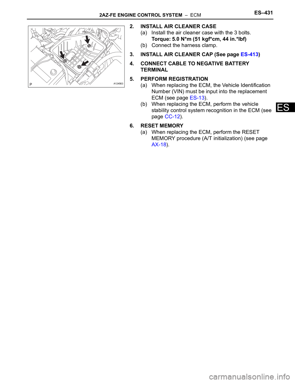
2. INSTALL AIR CLEANER CASE
(a) Install the air cleaner case with the 3 bolts.
Torque: 5.0 N*m (51 kgf*cm, 44 in.*lbf)
(b) Connect the harness clamp.
3. INSTALL AIR CLEANER CAP (See page ES-413)
4. CONNECT CABLE TO NEGATIVE BATTERY
TERMINAL
5. PERFORM REGISTRATION
(a) When replacing the ECM, the Vehicle Identification
Number (VIN) must be input into the replacement
ECM (see page ES-13).
(b) When replacing the ECM, perform the vehicle
stability control system recognition in the ECM (see
page CC-12).
6. RESET MEMORY
(a) When replacing the ECM, perform the RESET
MEMORY procedure (A/T initialization) (see page
AX-18).
A124563
Page 189 of 2000
2GR-FE ENGINE CONTROL SYSTEM – SFI SYSTEMES–3
ES
PARTS LOCATION
A136802E02
Page 190 of 2000
ES–42GR-FE ENGINE CONTROL SYSTEM – SFI SYSTEM
ES
A136801E02
Trending: front suspension, air suspension, rear suspension, valve body, water pump, check oil, suspension


