sensor TOYOTA RAV4 2006 Service Repair Manual
[x] Cancel search | Manufacturer: TOYOTA, Model Year: 2006, Model line: RAV4, Model: TOYOTA RAV4 2006Pages: 2000, PDF Size: 45.84 MB
Page 1556 of 2000
BRAKE CONTROL – VEHICLE STABILITY CONTROL SYSTEMBC–53
BC
FREEZE FRAME DATA
1. FREEZE FRAME DATA
HINT:
• Whenever a DTC is detected or the ABS operates,
the skid control ECU stores the current vehicle
(sensor) state as freeze frame data.
• The skid control ECU stores the number of times
(maximum: 31) the ignition switch has been turned
from OFF to ON since the last time the ABS was
activated. However, if the vehicle was stationary or
running at a low speed (7 km/h [4.3 mph] or less), or if
a DTC is detected, the skid control ECU stops
counting.
• Freeze frame data at the time the ABS operates:
The skid control ECU stores and updates the data
whenever the ABS system operates.
When the ECU stores data at the time a DTC is
detected, the data stored when the ABS operated is
erased.
• Freeze frame data at the time a DTC is detected:
When the skid control ECU stores data at the time a
DTC is detected, no updates will be performed until
the data is cleared.
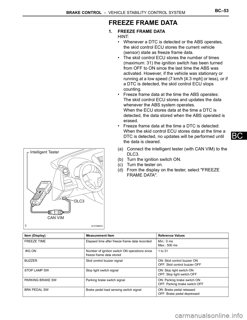
(a) Connect the intelligent tester (with CAN VIM) to the
DLC3.
(b) Turn the ignition switch ON.
(c) Turn the tester on.
(d) From the display on the tester, select "FREEZE
FRAME DATA".
B127989E01
Item (Display) Measurement Item Reference Values
FREEZE TIME Elapsed time after freeze frame data recorded Min.: 0 ms
Max.: 500 ms
#IG ON Number of ignition switch ON operations since
freeze frame data stored1 to 31
BUZZER Skid control buzzer signal ON: Skid control buzzer ON
OFF: Skid control buzzer OFF
STOP LAMP SW Stop light switch signal ON: Stop light switch ON
OFF: Stop light switch OFF
PARKING BRAKE SW Parking brake switch signal ON: Parking brake switch ON
OFF: Parking brake switch OFF
BRK PEDAL SW Brake pedal load sensing switch signal ON: Brake pedal released
OFF: Brake pedal depressed
Page 1557 of 2000

BC–54BRAKE CONTROL – VEHICLE STABILITY CONTROL SYSTEM
BC
GEAR POSITION Gear position information FAIL
1st
2nd
3rd
4th
5th
6th
P, N
R
NOT R
LEVER POSITION Shift lever position information FAIL
1st
2nd
3rd
4th
5th
6th/B
D/M
P, N
R
OPERATED SYSTEM Operated system status ABS: ABS activated
VSC: VSC activated
TRC: TRC activated
BA: BA activated
FAIL: Fail safe mode activated
HA-CTRL: Hill-start assist control activated
SYS: System prohibited
NON: No system activated
MAS CYL PRESS 1 Master cylinder pressure sensor reading Brake pedal released: 0.3 V to 0.9 V
Brake pedal depressed: 0.8 V to 4.5 V
M/C Sensor Grade Master cylinder pressure sensor change Min.: -30 MPa/s
Max.: 225 MPa/s
YAW RATE Yaw rate sensor reading Min.: -128 deg/s
Max.: 127 deg/s
STEERING SEN Steering sensor reading Left turn: Increase
Right turn: Decrease
LATERAL G Lateral G
Min.: -25.11 m/s
2
Max.: 24.91 m/s2
FORWARD&REA G Forward and backward G
Min.: -25.11 m/s2
Max.: 24.91 m/s2
FR WHEEL SPD FR wheel speed Min.: 0 km/h (0 mph)
Max.: 326.4 km/h (202.8 mph)
FL WHEEL SPD FL wheel speed Min.: 0 km/h (0 mph)
Max.: 326.4 km/h (202.8 mph)
RR WHEEL SPD RR wheel speed Min.: 0 km/h (0 mph)
Max.: 326.4 km/h (202.8 mph)
RL WHEEL SPD RL wheel speed Min.: 0 km/h (0 mph)
Max.: 326.4 km/h (202.8 mph)
VEHICLE SPD Vehicle speed Min.: 0 km/h (0 mph)
Max.: 326.4 km/h (202.8 mph)
SPD GARDE Vehicle speed grade
Min.: -25.11 m/s
2
Max.: 24.91 m/s2
ENGINE TORQUE Real engine torque Min.: -1024 Nm
Max.: 1023 Nm
ACCELERATOR % Accelerator pedal opening angle % Min.: 0%
Max.: 128%
INSPECTION MODE Inspection mode OTHER: Normal
INSPECT: Service Item (Display) Measurement Item Reference Values
Page 1558 of 2000

BRAKE CONTROL – VEHICLE STABILITY CONTROL SYSTEMBC–55
BC
FAIL-SAFE CHART
1. FAIL SAFE OPERATION
• If there is a problem with any sensor signals or
actuator systems, the skid control ECU prohibits the
power supply to the ABS and TRACTION actuator
and informs the ECM of VSC system failure.
The ABS and TRACTION actuator turns off the
solenoids and the ECM s huts off VSC control (traction
control signal) from the skid control ECU accordingly,
the result being that it is as if the ABS, TRC and VSC
systems were not installed.
• ABS control is prohibited, but EBD control continues
as far as possible. If EBD control is impossible, the
BRAKE warning light comes on to warn the driver
(see page BC-44).
• If system components have any malfunctions before
starting control, the operation stops immediately. If
system components have any malfunctions during
control, the control stops gradually so as not to trigger
a sudden change in vehicle conditions.
If it is impossible to control the systems, the warning
light comes on to inform the driver of malfunctions in
the systems (see page BC-44).
HINT:
• If the ABS system malfunctions, the brake system
operates normally without the ABS system.
• If the brake actuator malfunctions, a gradual loss of
brake performance is expected, and ABS system
control is prohibited.
ABS, EBD and BA system
TRC and VSC system:
Malfunction Area Fail-Safe Operation
ABS system ABS, BA, TRC and VSC control prohibited
BA system ABS, BA, TRC and VSC control prohibited
EBD system ABS, EBD, BA, TRC and VSC control prohibited
Malfunction Area Fail-Safe Operation
Engine control system
(TRC and VSC systems)Before control: Disables control
During control: Uses only the brakes to effect control
Brake control system
(VSC system)Before control: Disables control
During control: Uses only the engine to effect control
Brake control system
(TRC system)Before control: Disables control
During control: Disables control (by gradually ending control)
Page 1559 of 2000

BC–56BRAKE CONTROL – VEHICLE STABILITY CONTROL SYSTEM
BC
DATA LIST / ACTIVE TEST
1. READ DATA LIST
HINT:
Using the intelligent tester's DATA LIST allows switch,
sensor, actuator and other item values to be read without
out removing any parts. Reading the DATA LIST early in
troubleshooting is one way to save time.
(a) Connect the intelligent tester (with CAN VIM) to the
DLC3.
(b) Turn the ignition switch ON.
(c) Turn the intelligent tester on.
(d) Read the DATA LIST according to the display on the
tester.
Skid control ECU
Tester Display Measurement Item/Range Normal Condition Diagnostic Note
ABS WARN LAMP ABS warning light / ON or OFF ON: ABS warning light ON
OFF: ABS warning light OFF-
VSC WARN LAMP VSC warning light / ON or OFF ON: VSC warning light ON
OFF: VSC warning light OFF-
BRAKE WARN LAMP Brake warning light / ON or OFF ON: Brake warning light ON
OFF: Brake warning light OFF-
SLIP INDI LAMP Slip indicator light / ON or OFF ON: Slip indicator light ON
OFF: Slip indicator light OFF-
D-HILL LIGHT*9 Downhill assist control indicator
light / ON or OFFON: Downhill assist control switch
ON
OFF: Downhill assist control
switch OFF-
AUTO LSD LAMP*10 AUTO LSD indicator light / ON or
OFFON: Traction control switch ON
OFF: Traction control switch OFF-
BUZZER Skid control buzzer / ON or OFF ON: Buzzer ON
OFF: Buzzer OFF-
STOP LAMP SW Stop light switch / ON or OFF ON: Brake pedal depressed
OFF: Brake pedal released-
PARKING BRAKE SW Parking brake switch / ON or OFF ON: Parking brake applied
OFF: Parking brake released-
BRK PEDAL SW Brake pedal load sensing switch /
ON or OFFON: Brake pedal depressed
beyond the specified point
OFF: Brake pedal not depressed
beyond the specified point-
IDLE SW Main idle switch / ON or OFF ON: Accelerator pedal released
OFF: Accelerator pedal
depressed-
DAC SW*9 Downhill assist control switch /
ON or OFFON: Downhill assist control switch
ON
ON: Downhill assist control switch
ON-
AUTO LSD SW*10 AUTO LSD switch / ON or OFF ON: AUTO LSD switch ON
ON: AUTO LSD switch ON-
GEAR POSITION Gear position information / P/N,
R, 1st-6th, FAIL, NOT R--
LEVER POSITION Shift lever position information / P/
N, R, D/M, 1st-6th/B, FAIL--
SHIFT INFO Shift information / ON or OFF ON: During gear change -
MAS CYL PRESS 1 Master cylinder pressure sensor 1
reading / min.: 0 V, max.: 5 VWhen brake pedal released: 0.3
to 0.9 VReading increases when brake
pedal depressed
ZERO M/C SEN Memorized zero point value of
master cylinder pressure sensor /
min.: -12.5 MPa, max.: 12.4 MPaMin.: -12.5 MPa
Max.: 12.4 MPa-
Page 1560 of 2000

BRAKE CONTROL – VEHICLE STABILITY CONTROL SYSTEMBC–57
BC
DECELERAT SEN Deceleration sensor 1 reading /
min.: -18.52 m/s2, max.: 18.39 m/
s2
Min.: -18.52 m/s2
Max.: 18.39 m/s2
-
ZERO DECELERAT Memorized zero point value of
deceleration sensor 1 / min.: -
25.11 m/s
2, max.: 24.91 m/s2
Min.: -25.11 m/s2
Max.: 24.91 m/s2
-
DECELERAT SEN 2 Deceleration sensor 2 reading /
min.: -18.52 m/s
2, max.: 18.39 m/
s2
Min.: -18.52 m/s2
Max.: 18.39 m/s2
-
ZERO DECELERAT 2 Memorized zero point value of
deceleration sensor 2 / min.: -
25.11 m/s
2, max.: 24.91 m/s2
Min.: -25.11 m/s2
Max.: 24.91 m/s2
-
YAW RATE SENS 1 Yaw rate sensor 1 reading / min.: -
128 deg/s, max.: 127 deg/sMin.: -128 deg/s
Max.: 127 deg/s-
YAW RATE SENS 2 Yaw rate sensor 2 reading / min.: -
128 deg/s, max.: 127 deg/sMin.: -128 deg/s
Max.: 127 deg/s-
ZERO YAW RATE Memorized zero point value of
yaw rate sensor 1 / min.: -128
deg/s, max.: 127 deg/sMin.: -128 deg/s
Max.: 127 deg/s-
STEERING SEN Steering sensor reading / min.: -
3276.8 deg, max.: 3276.7 degLeft turn: Increase
Right turn: Decrease-
ZERO STEERING Memorized zero point value of
steering sensor / min.: -3276.8
deg, max.: 3276.7 degMin.: -3276.8 deg
Max.: 3276.7 deg-
LATERAL G
Lateral G / min.: -25.11 m/s
2,
max.: 24.91 m/s2Min.: -25.11 m/s2
Max.: 24.91 m/s2
-
FORWARD&REA G Forward and rearward G / min.: -
25.11 m/s
2, max.: 24.91 m/s2Min.: -25.11 m/s2
Max.: 24.91 m/s2
-
YAW RATE VALUE Yaw rate value / min.: -128 deg/s,
max.: 127 deg/sMin.: -128 deg/s
Max.: 127 deg/s-
STEERING ANGLE Steering angle value / min.: -
3276.8 deg, max.: 3276.7 degMin.: -3276.8 deg
Max.: 3276.7 deg-
FR WHEEL SPD Wheel speed sensor (FR) reading
/ min.: 0 km/h (0 mph), max.:
326.4 km/h (202.8 mph)Actual wheel speed Similar to speed indicated on
speedometer
FL WHEEL SPD Wheel speed sensor (FL) reading
/ min.: 0 km/h (0 mph), max.:
326.4 km/h (202.8 mph)Actual wheel speed Similar to speed indicated on
speedometer
RR WHEEL SPD Wheel speed sensor (RR) reading
/ min.: 0 km/h (0 mph), max.:
326.4 km/h (202.8 mph)Actual wheel speed Similar to speed indicated on
speedometer
RL WHEEL SPD Wheel speed sensor (RL) reading
/ min.: 0 km/h (0 mph), max.:
326.4 km/h (202.8 mph)Actual wheel speed Similar to speed indicated on
speedometer
VEHICLE SPD Maximum speed sensor reading /
min.: 0 km/h (0 mph), max.: 326.4
km/h (202.8 mph)Actual wheel speed Similar to speed indicated on
speedometer
FR WHEEL ACCEL FR wheel acceleration / min.: -
200.84 m/s
2, max.: 199.27 m/s2Min.: -200.84 m/s2
Max.: 199.27 m/s2
-
FL WHEEL ACCEL FL wheel acceleration / min.: -
200.84 m/s
2, max.: 199.271 m/s2Min.: -200.84 m/s2
Max.: 199.27 m/s2
-
RR WHEEL ACCEL RR wheel acceleration / min.: -
200.84 m/s
2, max.: 199.27 m/s2Min.: -200.84 m/s2
Max.: 199.27 m/s2
-
RL WHEEL ACCEL RL wheel acceleration / min.: -
200.84 m/s
2, max.: 199.27 m/s2Min.: -200.84 m/s2
Max.: 199.27 m/s2
- Tester Display Measurement Item/Range Normal Condition Diagnostic Note
Page 1562 of 2000

BRAKE CONTROL – VEHICLE STABILITY CONTROL SYSTEMBC–59
BC
HINT:
• *1: SFRH (S: Solenoid, F: Front, R: Right, H:
Holding)
• *2: SFRR (S: Solenoid, F: Front, R: Right, R:
Reduction)
• *3: SFLH (S: Solenoid, F: Front, L: Left, H:
Holding)
• *4: SFLR (S: Solenoid, F: Front, L: Left, R:
Reduction)
• *5: SRRH (S: Solenoid, R: Rear, R: Right, H:
Holding)
• *6: SRRR (S: Solenoid, R: Rear, R: Right, R:
Reduction)
• *7: SRLH (S: Solenoid, R: Rear, L: Left, H:
Holding)
• *8: SRLR (S: Solenoid, R: Rear, L: Left, R:
Reduction)
• *9: w/ Downhill assist control
• *10: for 2WD (w/ AUTO LSD)
SRLR*8 ABS solenoid (SRLR) / ON or
OFFON: Operates
OFF: Does not operate-
FR SPD OPN FR speed sensor open detection /
ERROR or NORMALERROR: Momentary interruption
NORMAL: Normal-
FL SPD OPN FL speed sensor open detection /
ERROR or NORMALERROR: Momentary interruption
NORMAL: Normal-
RR SPD OPN RR speed sensor open detection /
ERROR or NORMALERROR: Momentary interruption
NORMAL: Normal-
RL SPD OPN RL speed sensor open detection /
ERROR or NORMALERROR: Momentary interruption
NORMAL: Normal-
EFI COM OPN EFI communication open
detection / ERROR or NORMALERROR: Momentary interruption
NORMAL: Normal-
YAW RATE OPN Yaw rate sensor open detection /
ERROR or NORMALERROR: Momentary interruption
NORMAL: Normal-
DECELERAT OPN Deceleration sensor open
detection / ERROR or NORMALERROR: Momentary interruption
NORMAL: Normal-
STEERING OPN Steering angle sensor open
detection / ERROR or NORMALERROR: Momentary interruption
NORMAL: Normal-
M/C OPN Master cylinder pressure sensor
open detection / ERROR or
NORMALERROR: Momentary interruption
NORMAL: Normal-
#DTC Number of recorded DTCs/ min.:
0, max.: 255Min.: 0
Max.: 255-
INSPECTION MODE Inspection mode / OTHER or
INSPECT--
#IG ON2 Number of ignition switch ON
operations after entering the
inspection mode / min.: 0, max.:
255-- Tester Display Measurement Item/Range Normal Condition Diagnostic Note
Page 1597 of 2000
STEERING COLUMN – STEERING COLUMN ASSEMBLYSR–13
SR
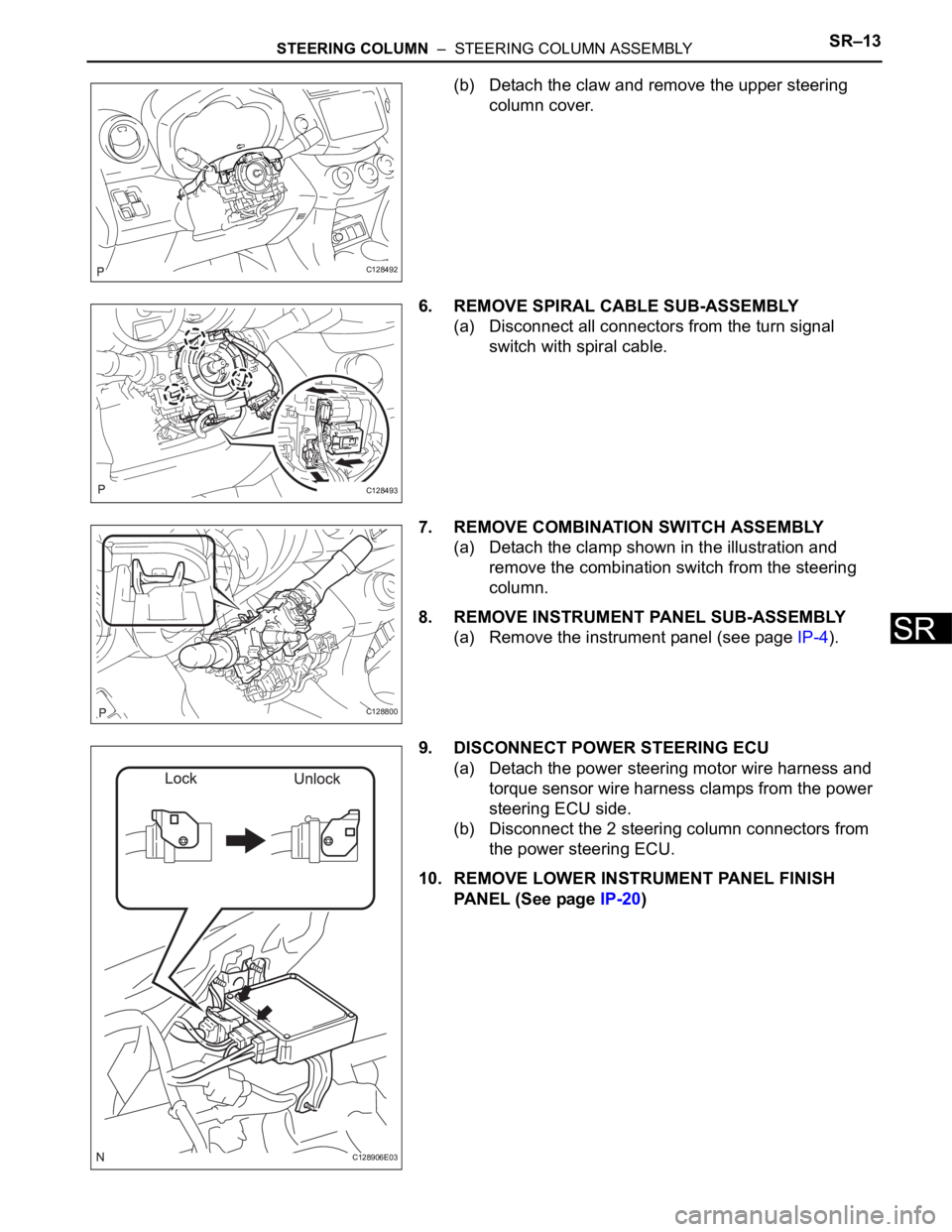
(b) Detach the claw and remove the upper steering
column cover.
6. REMOVE SPIRAL CABLE SUB-ASSEMBLY
(a) Disconnect all connectors from the turn signal
switch with spiral cable.
7. REMOVE COMBINATION SWITCH ASSEMBLY
(a) Detach the clamp shown in the illustration and
remove the combination switch from the steering
column.
8. REMOVE INSTRUMENT PANEL SUB-ASSEMBLY
(a) Remove the instrument panel (see page IP-4).
9. DISCONNECT POWER STEERING ECU
(a) Detach the power steering motor wire harness and
torque sensor wire harness clamps from the power
steering ECU side.
(b) Disconnect the 2 steering column connectors from
the power steering ECU.
10. REMOVE LOWER INSTRUMENT PANEL FINISH
PANEL (See page IP-20)
C128492
C128493
C128800
C128906E03
Page 1601 of 2000
STEERING COLUMN – STEERING COLUMN ASSEMBLYSR–17
SR
INSPECTION
1. CHECK TORQUE SENSOR
(a) Check the torque sensor (see page PS-19).
2. CHECK POWER STEERING MOTOR
(a) Check the power steering motor (see page PS-22).
3. CHECK MOTOR ROTATION ANGLE SENSOR
(a) Check the motor rotation angle sensor (see page
PS-25).
REASSEMBLY
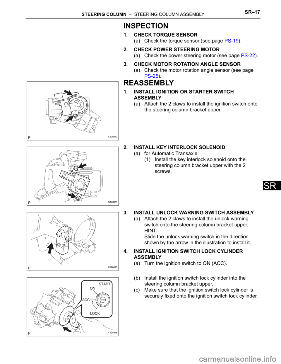
1. INSTALL IGNITION OR STARTER SWITCH
ASSEMBLY
(a) Attach the 2 claws to install the ignition switch onto
the steering column bracket upper.
2. INSTALL KEY INTERLOCK SOLENOID
(a) for Automatic Transaxle:
(1) Install the key interlock solenoid onto the
steering column bracket upper with the 2
screws.
3. INSTALL UNLOCK WARNING SWITCH ASSEMBLY
(a) Attach the 2 claws to install the unlock warning
switch onto the steering column bracket upper.
HINT:
Slide the unlock warning switch in the direction
shown by the arrow in the illustration to install it.
4. INSTALL IGNITION SWITCH LOCK CYLINDER
ASSEMBLY
(a) Turn the ignition switch to ON (ACC).
(b) Install the ignition switch lock cylinder into the
steering column bracket upper.
(c) Make sure that the ignition switch lock cylinder is
securely fixed onto the ignition switch lock cylinder.
C128812
C128811
C128815
C128816
Page 1604 of 2000
SR–20STEERING COLUMN – STEERING COLUMN ASSEMBLY
SR
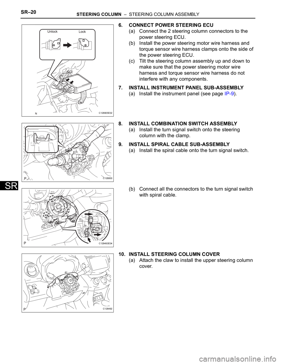
6. CONNECT POWER STEERING ECU
(a) Connect the 2 steering column connectors to the
power steering ECU.
(b) Install the power steering motor wire harness and
torque sensor wire harness clamps onto the side of
the power steering ECU.
(c) Tilt the steering column assembly up and down to
make sure that the power steering motor wire
harness and torque sensor wire harness do not
interfere with any components.
7. INSTALL INSTRUMENT PANEL SUB-ASSEMBLY
(a) Install the instrument panel (see page IP-9).
8. INSTALL COMBINATION SWITCH ASSEMBLY
(a) Install the turn signal switch onto the steering
column with the clamp.
9. INSTALL SPIRAL CABLE SUB-ASSEMBLY
(a) Install the spiral cable onto the turn signal switch.
(b) Connect all the connectors to the turn signal switch
with spiral cable.
10. INSTALL STEERING COLUMN COVER
(a) Attach the claw to install the upper steering column
cover.
C128905E02
C128800
C128493E04
C128492
Page 1608 of 2000
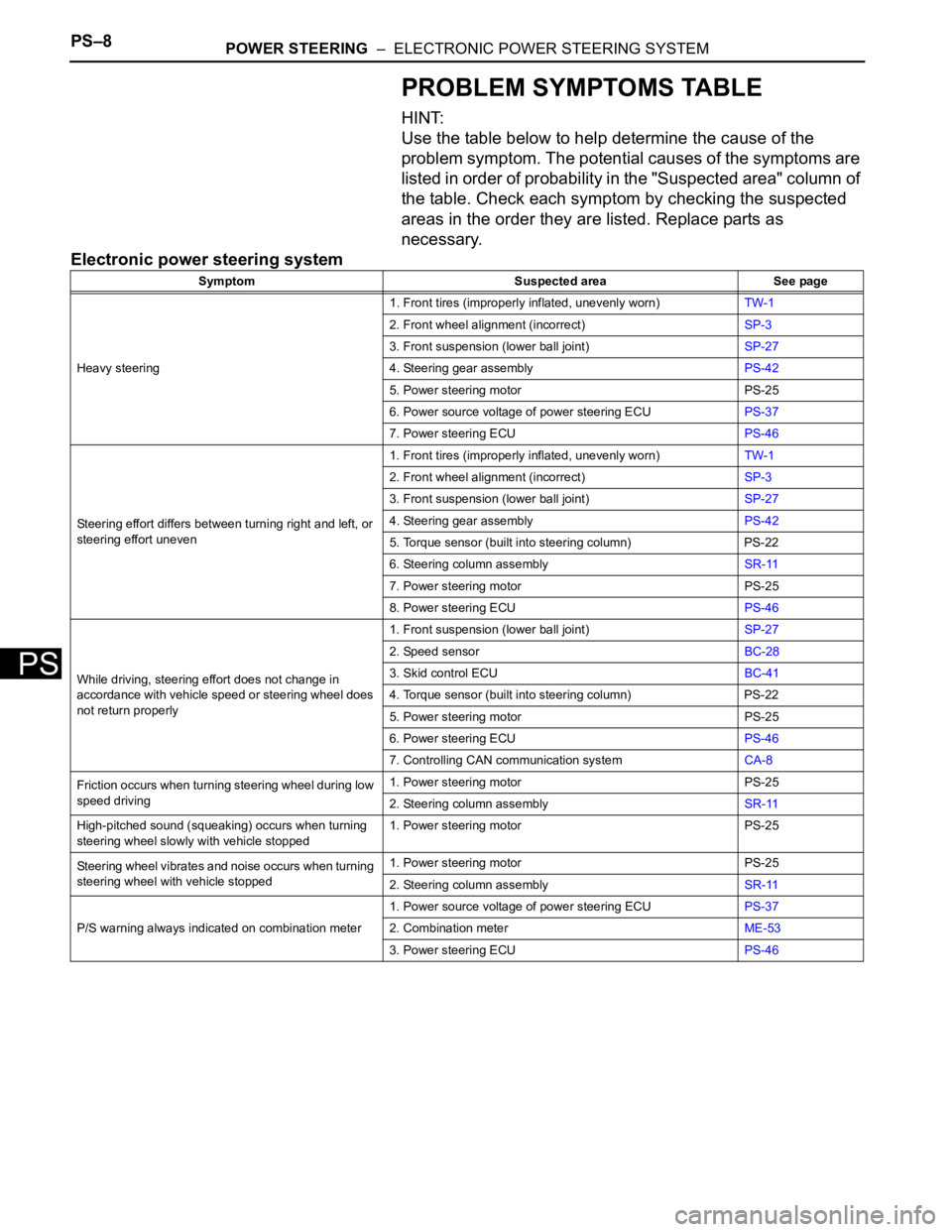
PS–8POWER STEERING – ELECTRONIC POWER STEERING SYSTEM
PS
PROBLEM SYMPTOMS TABLE
HINT:
Use the table below to help determine the cause of the
problem symptom. The potential causes of the symptoms are
listed in order of probability in the "Suspected area" column of
the table. Check each symptom by checking the suspected
areas in the order they are listed. Replace parts as
necessary.
Electronic power steering system
Symptom Suspected area See page
Heavy steering1. Front tires (improperly inflated, unevenly worn)TW-1
2. Front wheel alignment (incorrect)SP-3
3. Front suspension (lower ball joint)SP-27
4. Steering gear assemblyPS-42
5. Power steering motor PS-25
6. Power source voltage of power steering ECUPS-37
7. Power steering ECUPS-46
Steering effort differs between turning right and left, or
steering effort uneven1. Front tires (improperly inflated, unevenly worn)TW-1
2. Front wheel alignment (incorrect)SP-3
3. Front suspension (lower ball joint)SP-27
4. Steering gear assemblyPS-42
5. Torque sensor (built into steering column) PS-22
6. Steering column assemblySR-11
7. Power steering motor PS-25
8. Power steering ECUPS-46
While driving, steering effort does not change in
accordance with vehicle speed or steering wheel does
not return properly1. Front suspension (lower ball joint)SP-27
2. Speed sensorBC-28
3. Skid control ECUBC-41
4. Torque sensor (built into steering column) PS-22
5. Power steering motor PS-25
6. Power steering ECUPS-46
7. Controlling CAN communication systemCA-8
Friction occurs when turning steering wheel during low
speed driving1. Power steering motor PS-25
2. Steering column assemblySR-11
High-pitched sound (squeaking) occurs when turning
steering wheel slowly with vehicle stopped1. Power steering motor PS-25
Steering wheel vibrates and noise occurs when turning
steering wheel with vehicle stopped1. Power steering motor PS-25
2. Steering column assemblySR-11
P/S warning always indicated on combination meter1. Power source voltage of power steering ECUPS-37
2. Combination meterME-53
3. Power steering ECUPS-46