cruise control TOYOTA RAV4 2006 Service Owner's Manual
[x] Cancel search | Manufacturer: TOYOTA, Model Year: 2006, Model line: RAV4, Model: TOYOTA RAV4 2006Pages: 2000, PDF Size: 45.84 MB
Page 1816 of 2000
CRUISE CONTROL – CRUISE CONTROL SYSTEMCC–17
CC
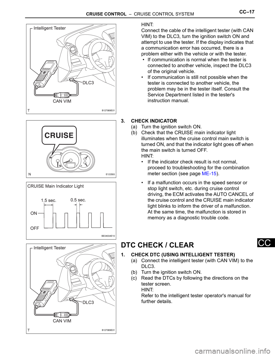
HINT:
Connect the cable of the intelligent tester (with CAN
VIM) to the DLC3, turn the ignition switch ON and
attempt to use the tester. If the display indicates that
a communication error has occurred, there is a
problem either with the vehicle or with the tester.
• If communication is normal when the tester is
connected to another vehicle, inspect the DLC3
of the original vehicle.
• If communication is still not possible when the
tester is connected to another vehicle, the
problem may be in the tester itself. Consult the
Service Department listed in the tester's
instruction manual.
3. CHECK INDICATOR
(a) Turn the ignition switch ON.
(b) Check that the CRUISE main indicator light
illuminates when the cruise control main switch is
turned ON, and that the indicator light goes off when
the main switch is turned OFF.
HINT:
• If the indicator check result is not normal,
proceed to troubleshooting for the combination
meter section (see page ME-15).
• If a malfunction occurs in the speed sensor or
stop light switch, etc. during cruise control
driving, the ECM activates the AUTO CANCEL of
the cruise control and the CRUISE main indicator
light blinks to inform the driver of a malfunction.
At the same time, the malfunction is stored in
memory as a diagnostic trouble code.
DTC CHECK / CLEAR
1. CHECK DTC (USING INTELLIGENT TESTER)
(a) Connect the intelligent tester (with CAN VIM) to the
DLC3.
(b) Turn the ignition switch ON.
(c) Read the DTCs by following the directions on the
tester screen.
HINT:
Refer to the intelligent tester operator's manual for
further details.
B127989E01
E123593
BE04034E10
B127989E01
Page 1817 of 2000
CC–18CRUISE CONTROL – CRUISE CONTROL SYSTEM
CC
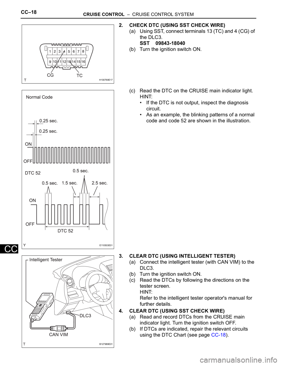
2. CHECK DTC (USING SST CHECK WIRE)
(a) Using SST, connect terminals 13 (TC) and 4 (CG) of
the DLC3.
SST 09843-18040
(b) Turn the ignition switch ON.
(c) Read the DTC on the CRUISE main indicator light.
HINT:
• If the DTC is not output, inspect the diagnosis
circuit.
• As an example, the blinking patterns of a normal
code and code 52 are shown in the illustration.
3. CLEAR DTC (USING INTELLIGENT TESTER)
(a) Connect the intelligent tester (with CAN VIM) to the
DLC3.
(b) Turn the ignition switch ON.
(c) Read the DTCs by following the directions on the
tester screen.
HINT:
Refer to the intelligent tester operator's manual for
further details.
4. CLEAR DTC (USING SST CHECK WIRE)
(a) Read and record DTCs from the CRUISE main
indicator light. Turn the ignition switch OFF.
(b) If DTCs are indicated, repair the relevant circuits
using the DTC Chart (see page CC-18).
H100769E17
E110503E01
B127989E01
Page 1818 of 2000

CRUISE CONTROL – CRUISE CONTROL SYSTEMCC–19
CC
(c) Clear the DTCs according to one of the following
procedures.
• Disconnect the negative (-) battery cable for
more than 1 minute.
• Remove the EFI NO. 1 and ETCS fuses from the
engine room relay block (located inside the
engine compartment) for more than 1 minute.
(d) Recheck for DTCs.
Page 1819 of 2000

CC–20CRUISE CONTROL – CRUISE CONTROL SYSTEM
CC
FAIL-SAFE CHART
HINT:
If the following conditions are detected while the cruise
control is in operation, the system clears the stored vehicle
speed in the ECM and cancels the cruise control operation.
Cruise control system
HINT:
*: w/ VSC
Vehicle Condition Auto Cancel Condition Fail-safe Deactivation Condition
CRUISE main indicator light blinks• There is open or short in stop light switch
circuit
• There is problem with vehicle speed
signal
• There is problem with throttle position
sensor and motor
• VSC is damaged*
• There is communication malfunction
between VSC and ECM*Turn cruise control main switch ON again
CRUISE main indicator light blinks• There is problem with input circuit of stop
light switch circuit
• There is problem with cancel circuitTurn ignition switch ON
Page 1820 of 2000

CRUISE CONTROL – CRUISE CONTROL SYSTEMCC–21
CC
DATA LIST / ACTIVE TEST
1. READ DATA LIST
HINT:
Using the intelligent tester's DATA LIST allows switch,
sensor, actuator and other item values to be read without
removing any parts. Reading the DATA LIST early in
troubleshooting is one way to save time.
(a) Connect the intelligent tester (with CAN VIM) to the
DLC3.
(b) Turn the ignition switch ON.
(c) Read the DATA LIST according to the display on the
tester.
ECM
Item Measurement Item / Display
(Range)Normal Condition Diagnostic Note
VEHICLE SPD Vehicle speed / min.: 0 km/h (0
mph) max.: 200 km/h (125 mph)Actual vehicle speed -
MEMORY SPD Vehicle speed / min.: 0 km/h (0
mph) max.: 200 km/h (125 mph)Actual vehicle speed stored in
memory-
THROTTLE Throttle operating angle / min.: 0
deg. max.: 125 deg.Actual demanded throttle angle -
CRUISE CONTROL Cruise control / ON or OFF ON: Cruise control is SET
OFF: Cruise control is UNSET-
MAIN SW (MAIN) Main switch (Main CPU) / ON or
OFFON: Main switch (Main CPU) is
SET
OFF: Main switch (Main CPU) is
UNSET-
CCS READY M Switch ready (Main CPU) / ON or
OFFON: Switch ready (Main CPU) is
SET
OFF: Switch ready (Main CPU) is
UNSET-
CCS INDICATOR M Switch indicator (Main CPU) / ON
or OFFON: Switch indicator (Main CPU)
is SET
OFF: Switch indicator (Main
CPU) is UNSET-
CANCEL SW CANCEL switch / ON or OFF ON: CANCEL switch is SET
OFF: CANCEL switch is UNSET-
SET/COAST SW - / SET switch / ON or OFF ON: - / SET switch is SET
OFF: - / SET switch is UNSET-
RES/ACC SW + / RES switch / ON or OFF ON: + / RES switch is SET
OFF: + / RES switch is UNSET-
STP LIGHT SW M Stop light switch signal (Main
CPU) / ON or OFFON: Brake pedal depressed
OFF: Brake pedal released-
SHIFT D POS Shift D position / ON or OFF ON: Shift is D or 3 position
OFF: Shift is except D or 3
position-
Page 1821 of 2000
CC–22CRUISE CONTROL – CRUISE CONTROL SYSTEM
CC
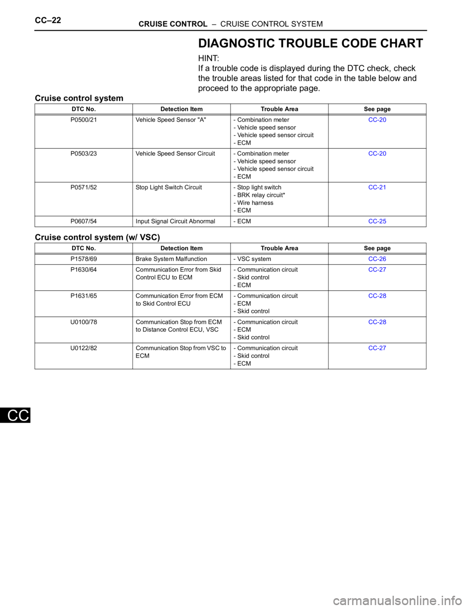
DIAGNOSTIC TROUBLE CODE CHART
HINT:
If a trouble code is displayed during the DTC check, check
the trouble areas listed for that code in the table below and
proceed to the appropriate page.
Cruise control system
Cruise control system (w/ VSC)
DTC No. Detection Item Trouble Area See page
P0500/21 Vehicle Speed Sensor "A" - Combination meter
- Vehicle speed sensor
- Vehicle speed sensor circuit
- ECMCC-20
P0503/23 Vehicle Speed Sensor Circuit - Combination meter
- Vehicle speed sensor
- Vehicle speed sensor circuit
- ECMCC-20
P0571/52 Stop Light Switch Circuit - Stop light switch
- BRK relay circuit*
- Wire harness
- ECMCC-21
P0607/54 Input Signal Circuit Abnormal - ECMCC-25
DTC No. Detection Item Trouble Area See page
P1578/69 Brake System Malfunction - VSC systemCC-26
P1630/64 Communication Error from Skid
Control ECU to ECM- Communication circuit
- Skid control
- ECMCC-27
P1631/65 Communication Error from ECM
to Skid Control ECU- Communication circuit
- ECM
- Skid controlCC-28
U0100/78 Communication Stop from ECM
to Distance Control ECU, VSC- Communication circuit
- ECM
- Skid controlCC-28
U0122/82 Communication Stop from VSC to
ECM- Communication circuit
- Skid control
- ECMCC-27
Page 1822 of 2000
CRUISE CONTROL – CRUISE CONTROL SYSTEMCC–23
CC
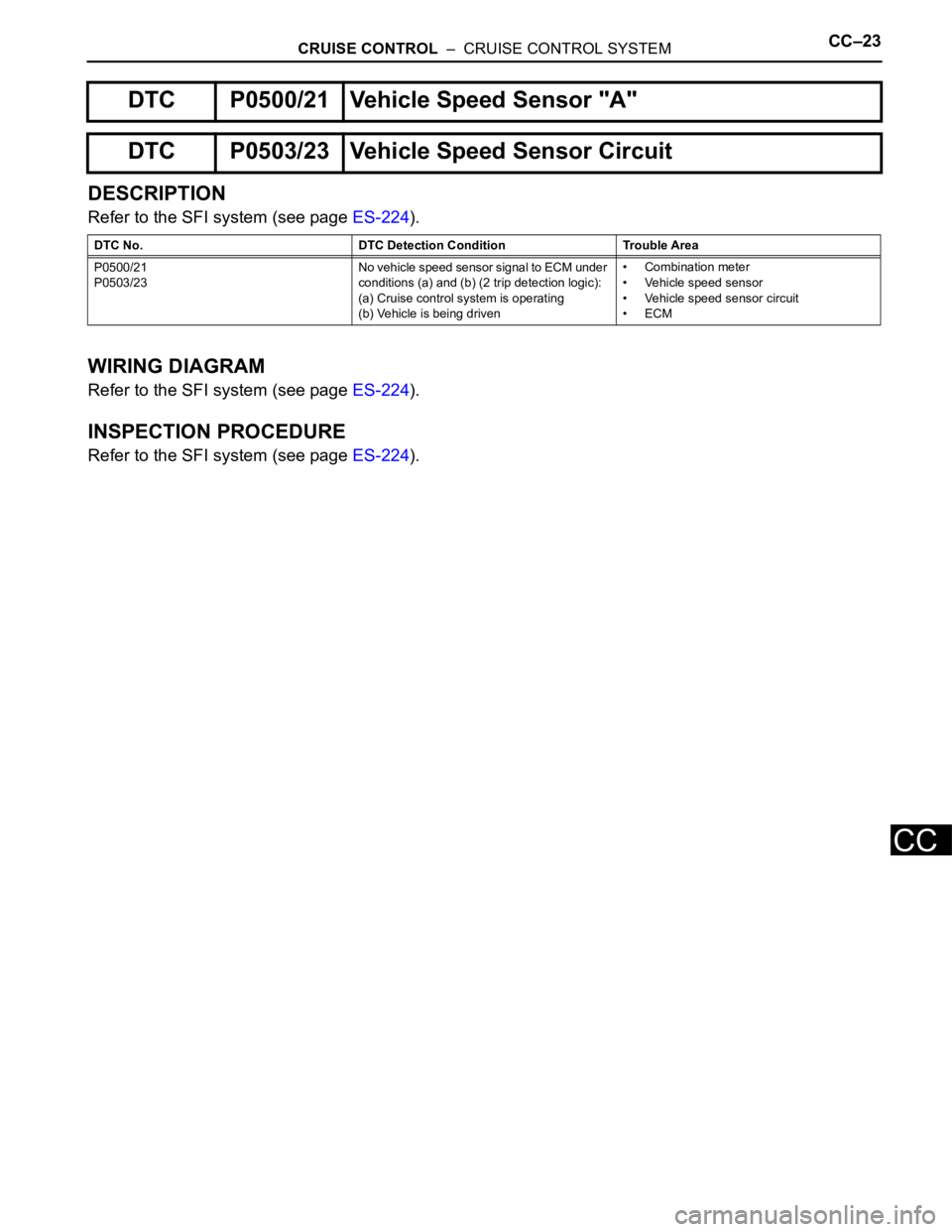
DESCRIPTION
Refer to the SFI system (see page ES-224).
WIRING DIAGRAM
Refer to the SFI system (see page ES-224).
INSPECTION PROCEDURE
Refer to the SFI system (see page ES-224).
DTC P0500/21 Vehicle Speed Sensor "A"
DTC P0503/23 Vehicle Speed Sensor Circuit
DTC No. DTC Detection Condition Trouble Area
P0500/21
P0503/23No vehicle speed sensor signal to ECM under
conditions (a) and (b) (2 trip detection logic):
(a) Cruise control system is operating
(b) Vehicle is being driven• Combination meter
• Vehicle speed sensor
• Vehicle speed sensor circuit
•ECM
Page 1823 of 2000
CC–24CRUISE CONTROL – CRUISE CONTROL SYSTEM
CC
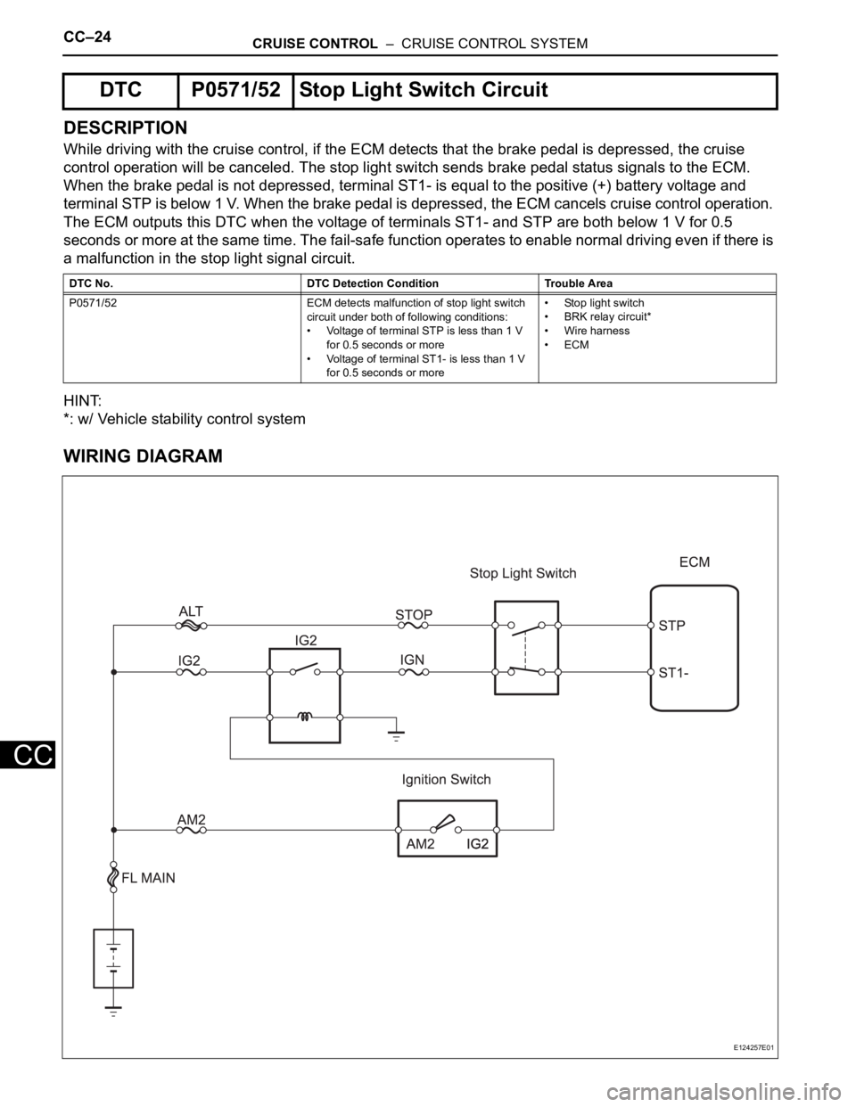
DESCRIPTION
While driving with the cruise control, if the ECM detects that the brake pedal is depressed, the cruise
control operation will be canceled. The stop light switch sends brake pedal status signals to the ECM.
When the brake pedal is not depressed, terminal ST1- is equal to the positive (+) battery voltage and
terminal STP is below 1 V. When the brake pedal is depressed, the ECM cancels cruise control operation.
The ECM outputs this DTC when the voltage of terminals ST1- and STP are both below 1 V for 0.5
seconds or more at the same time. The fail-safe function operates to enable normal driving even if there is
a malfunction in the stop light signal circuit.
HINT:
*: w/ Vehicle stability control system
WIRING DIAGRAM
DTC P0571/52 Stop Light Switch Circuit
DTC No. DTC Detection Condition Trouble Area
P0571/52 ECM detects malfunction of stop light switch
circuit under both of following conditions:
• Voltage of terminal STP is less than 1 V
for 0.5 seconds or more
• Voltage of terminal ST1- is less than 1 V
for 0.5 seconds or more• Stop light switch
• BRK relay circuit*
• Wire harness
•ECM
E124257E01
Page 1824 of 2000
CRUISE CONTROL – CRUISE CONTROL SYSTEMCC–25
CC
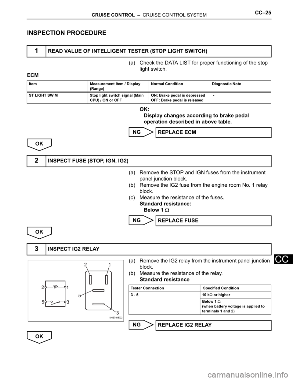
INSPECTION PROCEDURE
(a) Check the DATA LIST for proper functioning of the stop
light switch.
ECM
OK:
Display changes according to brake pedal
operation described in above table.
NG
OK
(a) Remove the STOP and IGN fuses from the instrument
panel junction block.
(b) Remove the IG2 fuse from the engine room No. 1 relay
block.
(c) Measure the resistance of the fuses.
Standard resistance:
Below 1
NG
OK
(a) Remove the IG2 relay from the instrument panel junction
block.
(b) Measure the resistance of the relay.
Standard resistance
NG
OK
1READ VALUE OF INTELLIGENT TESTER (STOP LIGHT SWITCH)
Item Measurement Item / Display
(Range) Normal Condition Diagnostic Note
ST LIGHT SW M Stop light switch signal (Main
CPU) / ON or OFF ON: Brake pedal is depressed
OFF: Brake pedal is released -
REPLACE ECM
2INSPECT FUSE (STOP, IGN, IG2)
REPLACE FUSE
3INSPECT IG2 RELAY
I045791E02
Tester Connection Specified Condition
3 - 5 10 k
or higher
Below 1
(when battery voltage is applied to
terminals 1 and 2)
REPLACE IG2 RELAY
Page 1825 of 2000
CC–26CRUISE CONTROL – CRUISE CONTROL SYSTEM
CC
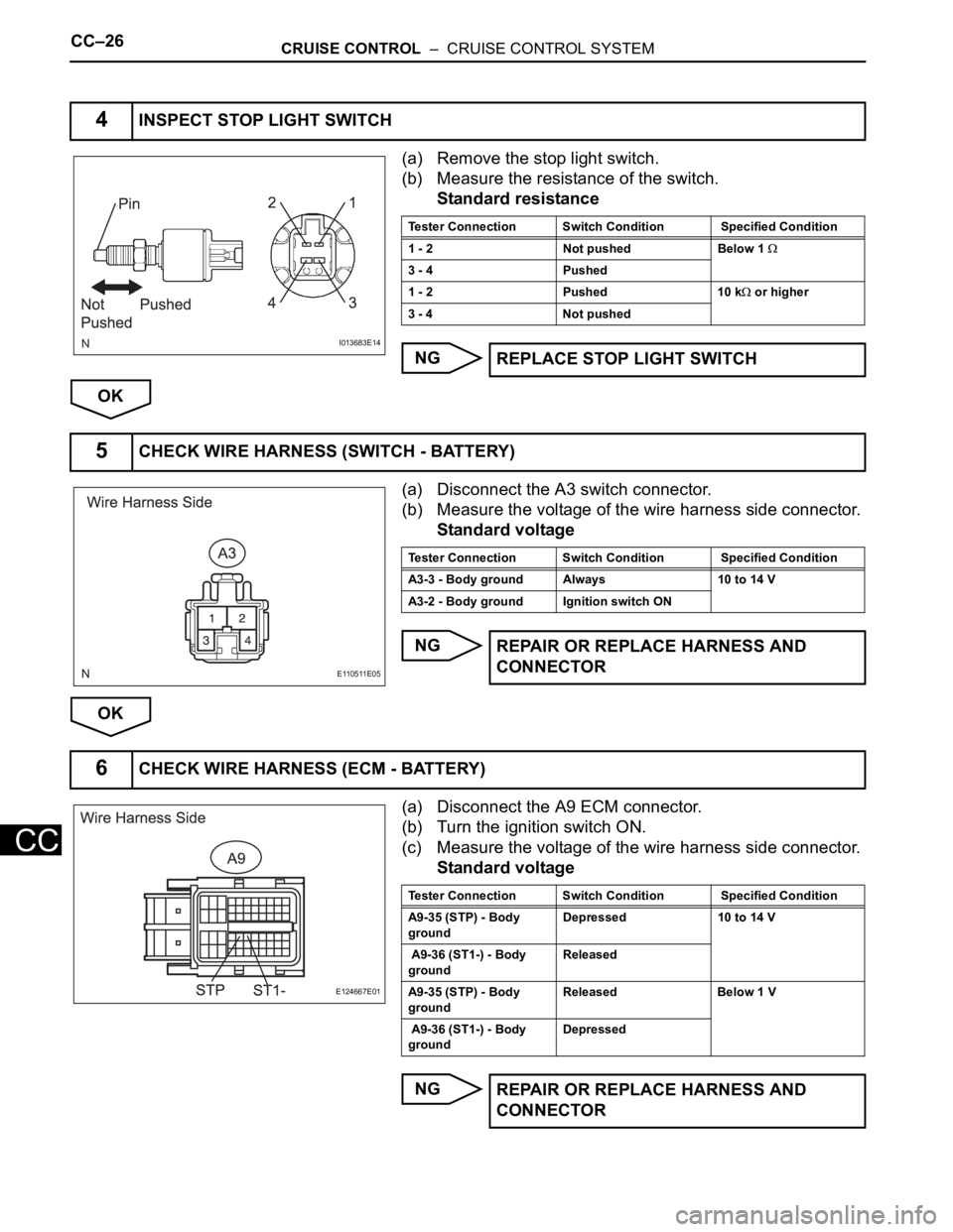
(a) Remove the stop light switch.
(b) Measure the resistance of the switch.
Standard resistance
NG
OK
(a) Disconnect the A3 switch connector.
(b) Measure the voltage of the wire harness side connector.
Standard voltage
NG
OK
(a) Disconnect the A9 ECM connector.
(b) Turn the ignition switch ON.
(c) Measure the voltage of the wire harness side connector.
Standard voltage
NG
4INSPECT STOP LIGHT SWITCH
I013683E14
Tester Connection Switch Condition Specified Condition
1 - 2 Not pushed Below 1
3 - 4 Pushed
1 - 2 Pushed 10 k
or higher
3 - 4 Not pushed
REPLACE STOP LIGHT SWITCH
5CHECK WIRE HARNESS (SWITCH - BATTERY)
E110511E05
Tester Connection Switch Condition Specified Condition
A3-3 - Body ground Always 10 to 14 V
A3-2 - Body ground Ignition switch ON
REPAIR OR REPLACE HARNESS AND
CONNECTOR
6CHECK WIRE HARNESS (ECM - BATTERY)
E124667E01
Tester Connection Switch Condition Specified Condition
A9-35 (STP) - Body
ground Depressed 10 to 14 V
A9-36 (ST1-) - Body
ground Released
A9-35 (STP) - Body
ground Released Below 1 V
A9-36 (ST1-) - Body
ground Depressed
REPAIR OR REPLACE HARNESS AND
CONNECTOR