sensor TOYOTA RAV4 2006 Service Manual PDF
[x] Cancel search | Manufacturer: TOYOTA, Model Year: 2006, Model line: RAV4, Model: TOYOTA RAV4 2006Pages: 2000, PDF Size: 45.84 MB
Page 203 of 2000
EM–282GR-FE ENGINE MECHANICAL – ENGINE ASSEMBLY
EM
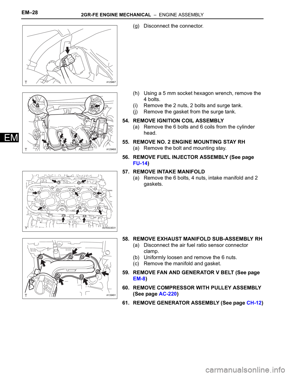
(g) Disconnect the connector.
(h) Using a 5 mm socket hexagon wrench, remove the
4 bolts.
(i) Remove the 2 nuts, 2 bolts and surge tank.
(j) Remove the gasket from the surge tank.
54. REMOVE IGNITION COIL ASSEMBLY
(a) Remove the 6 bolts and 6 coils from the cylinder
head.
55. REMOVE NO. 2 ENGINE MOUNTING STAY RH
(a) Remove the bolt and mounting stay.
56. REMOVE FUEL INJECTOR ASSEMBLY (See page
FU-14)
57. REMOVE INTAKE MANIFOLD
(a) Remove the 6 bolts, 4 nuts, intake manifold and 2
gaskets.
58. REMOVE EXHAUST MANIFOLD SUB-ASSEMBLY RH
(a) Disconnect the air fuel ratio sensor connector
clamp.
(b) Uniformly loosen and remove the 6 nuts.
(c) Remove the manifold and gasket.
59. REMOVE FAN AND GENERATOR V BELT (See page
EM-8)
60. REMOVE COMPRESSOR WITH PULLEY ASSEMBLY
(See page AC-220)
61. REMOVE GENERATOR ASSEMBLY (See page CH-12)
A129467
A129468
A076533E01
A139491
Page 205 of 2000
EM–302GR-FE ENGINE MECHANICAL – ENGINE ASSEMBLY
EM
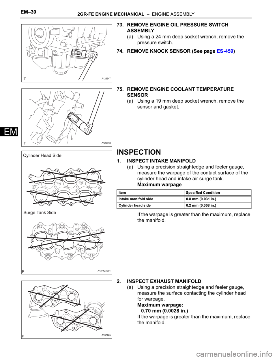
73. REMOVE ENGINE OIL PRESSURE SWITCH
ASSEMBLY
(a) Using a 24 mm deep socket wrench, remove the
pressure switch.
74. REMOVE KNOCK SENSOR (See page ES-459)
75. REMOVE ENGINE COOLANT TEMPERATURE
SENSOR
(a) Using a 19 mm deep socket wrench, remove the
sensor and gasket.
INSPECTION
1. INSPECT INTAKE MANIFOLD
(a) Using a precision straightedge and feeler gauge,
measure the warpage of the contact surface of the
cylinder head and intake air surge tank.
Maximum warpage
If the warpage is greater than the maximum, replace
the manifold.
2. INSPECT EXHAUST MANIFOLD
(a) Using a precision straightedge and feeler gauge,
measure the surface contacting the cylinder head
for warpage.
Maximum warpage:
0.70 mm (0.0028 in.)
If the warpage is greater than the maximum, replace
the manifold.
A129647
A129648
A137423E01
Item Specified Condition
Intake manifold side 0.8 mm (0.031 in.)
Cylinder head side 0.2 mm (0.008 in.)
A137425
Page 220 of 2000

IN–48INTRODUCTION – TERMS
IN
GLOSSARY OF SAE AND TOYOTA
TERMS
This glossary lists all SAE-J1930 terms and abbreviations
used in this manual in compliance with SAE
recommendations, as well as their TOYOTA equivalents.
SAE
ABBREVIATIONSSAE TERMS TOYOTA TERMS ( )-ABBREVIATIONS
3GR Third Gear -
4GR Fourth Gear -
A/C Air Conditioning Air Conditioner
ACL Air Cleaner Air Cleaner, A/CL
AIR Secondary Air Injection Air Injection (AI)
AP Accelerator Pedal -
B+ Battery Positive Voltage +B, Battery Voltage
BARO Barometric Pressure HAC
CAC Charge Air Cooler Intercooler
CARB Carburetor Carburetor
CFI Continuous Fuel Injection -
CKP Crankshaft Position Crank Angle
CL Closed Loop Closed Loop
CMP Camshaft Position Cam Angle
CPP Clutch Pedal Position -
CTOX Continuous Trap Oxidizer -
CTP Closed Throttle Position LL ON, Idle ON
DFI Direct Fuel Injection Direct Injection (DI/INJ)
DI Distributor Ignition -
DLC3 Data Link Connector 3 OBD II Diagnostic Connector
DTC Diagnostic Trouble Code Diagnostic Trouble Code
DTM Diagnostic Test Mode -
ECL Engine Coolant Level -
ECM Engine Control Module Engine Electronic Control Unit (ECU)
ECT Engine Coolant Temperature Coolant Temperature, Water Temperature (THW)
EEPROM Electrically Erasable Programmable Read Only MemoryElectrically Erasable Programmable Read Only Memory
(EEPROM)
EFE Early Fuel Evaporation Cold Mixture Heater (CMH), Heat Control Valve (HCV)
EGR Exhaust Gas Recirculation Exhaust Gas Recirculation (EGR)
EI Electronic Ignition Distributorless Ignition (DLI)
EM Engine Modification Engine Modification (EM)
EPROM Erasable Programmable Read Only Memory Programmable Read Only Memory (PROM)
EVAP Evaporative Emission Evaporative Emission Control (EVAP)
FC Fan Control -
FEEPROMFlash Electrically Erasable Programmable Read Only
Memory-
FEPROM Flash Erasable Programmable Read Only Memory -
FF Flexible Fuel -
FP Fuel Pump Fuel Pump
GEN Generator Alternator
GND Ground Ground (GND)
HO2S Heated Oxygen Sensor Heated Oxygen Sensor (HO2S)
IAC Idle Air Control Idle Speed Control (ISC)
Page 221 of 2000

INTRODUCTION – TERMSIN–49
IN
IAT Intake Air Temperature Intake or Inlet Air Temperature
ICM Ignition Control Module -
IFI Indirect Fuel Injection Indirect Injection (IDL)
IFS Inertia Fuel-Shutoff -
ISC Idle Speed Control -
KS Knock Sensor Knock Sensor
MAF Mass Airflow Air Flow Meter
MAP Manifold Absolute Pressure Manifold Pressure Intake Vacuum
MC Mixture ControlElectric Bleed Air Control Valve (EBCV)
Mixture Control Valve (MCV)
Electric Air Control Valve (EACV)
MDP Manifold Differential Pressure -
MFI Multiport Fuel Injection Electronic Fuel Injection (EFI)
MIL Malfunction Indicator Lamp Check Engine Lamp
MST Manifold Surface Temperature -
MVZ Manifold Vacuum Zone -
NVRAM Non-Volatile Random Access Memory -
O2S Oxygen Sensor Oxygen Sensor, O2 Sensor (O2S)
OBD On-Board Diagnostic On-Board Diagnostic System (OBD)
OC Oxidation Catalytic Converter Oxidation Catalyst Converter (OC), CCo
OL Open Loop Open Loop
PAIR Pulsed Secondary Air Injection Air Suction (AS)
PCM Powertrain Control Module -
PNP Park/Neutral Position -
PROM Programmable Read Only Memory -
PSP Power Steering Pressure -
PTOX Periodic Trap OxidizerDiesel Particulate Filter (DPF)
Diesel Particulate Trap (DPT)
RAM Random Access Memory Random Access Memory (RAM)
RM Relay Module -
ROM Read Only Memory Read Only Memory (ROM)
RPM Engine Speed Engine Speed
SC Supercharger Supercharger
SCB Supercharger Bypass E-ABV
SFI Sequential Multiport Fuel Injection Electronic Fuel Injection (EFI), Sequential Injection
SPL Smoke Puff Limiter -
SRI Service Reminder Indicator -
SRT System Readiness Test -
ST Scan Tool -
TB Throttle Body Throttle Body
TBI Throttle Body Fuel InjectionSingle Point Injection
Central Fuel Injection (Ci)
TC Turbocharger Turbocharger
TCC Torque Converter Clutch Torque Converter
TCM Transmission Control Module Transmission ECU, ECT ECU
TP Throttle Position Throttle Position
TR Transmission Range -
TVV Thermal Vacuum ValveBimetallic Vacuum Switching Valve (BVSV)
Thermostatic Vacuum Switching Valve (TVSV) SAE
ABBREVIATIONSSAE TERMS TOYOTA TERMS ( )-ABBREVIATIONS
Page 222 of 2000

IN–50INTRODUCTION – TERMS
IN
TWC Three-Way Catalytic ConverterThree-Way Catalytic (TWC)
Manifold Converter
CCRO
TWC+OC Three-Way + Oxidation Catalytic Converter CCR + CCo
VAF Volume Airflow Air Flow Meter
VR Voltage Regulator Voltage Regulator
VSS Vehicle Speed Sensor Vehicle Speed Sensor
WOT Wide Open Throttle Full Throttle
WU-OC Warm Up Oxidation Catalytic Converter -
WU-TWC Warm Up Three-Way Catalytic Converter -SAE
ABBREVIATIONSSAE TERMS TOYOTA TERMS ( )-ABBREVIATIONS
Page 236 of 2000
EX–62AZ-FE EXHAUST – EXHAUST PIPE
EX
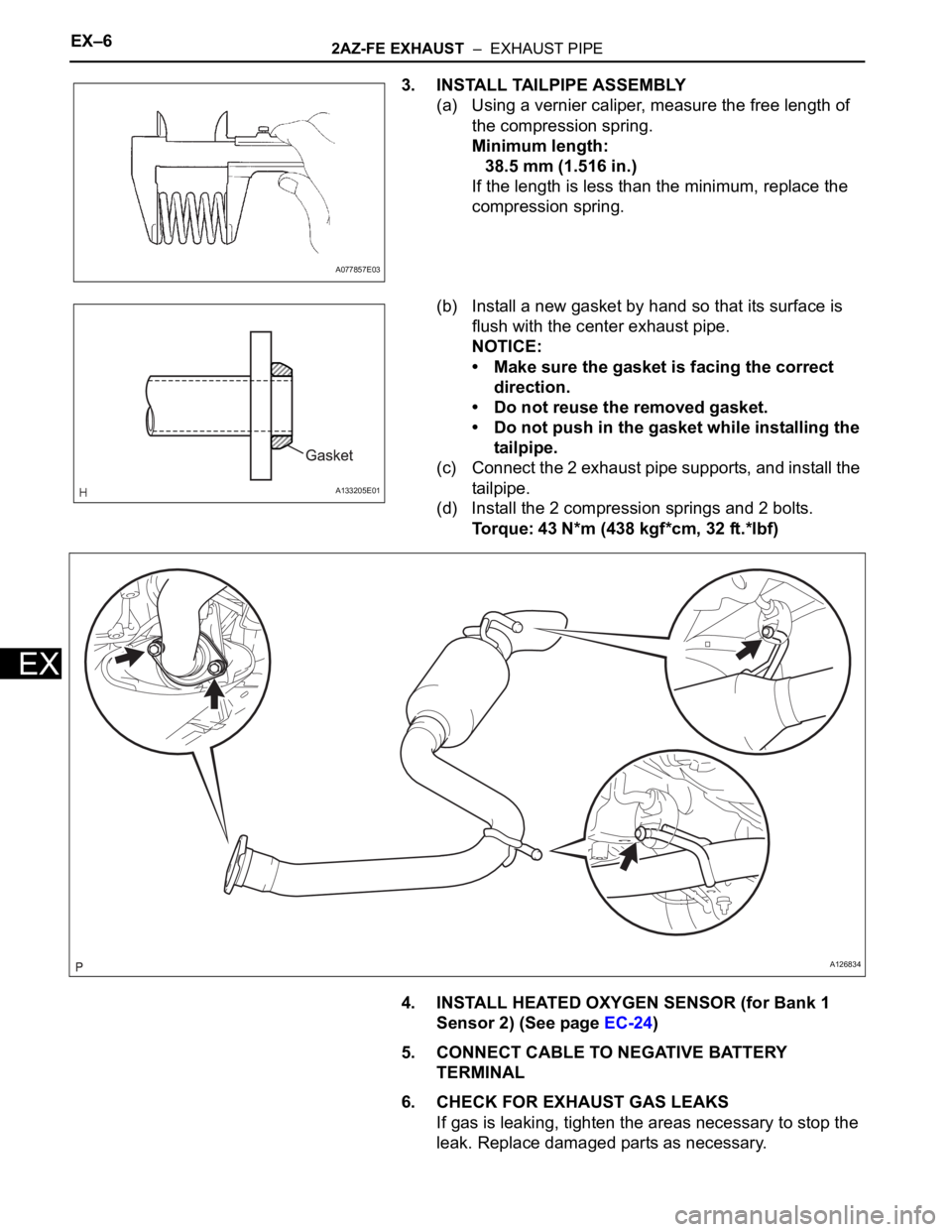
3. INSTALL TAILPIPE ASSEMBLY
(a) Using a vernier caliper, measure the free length of
the compression spring.
Minimum length:
38.5 mm (1.516 in.)
If the length is less than the minimum, replace the
compression spring.
(b) Install a new gasket by hand so that its surface is
flush with the center exhaust pipe.
NOTICE:
• Make sure the gasket is facing the correct
direction.
• Do not reuse the removed gasket.
• Do not push in the gasket while installing the
tailpipe.
(c) Connect the 2 exhaust pipe supports, and install the
tailpipe.
(d) Install the 2 compression springs and 2 bolts.
Torque: 43 N*m (438 kgf*cm, 32 ft.*lbf)
4. INSTALL HEATED OXYGEN SENSOR (for Bank 1
Sensor 2) (See page EC-24)
5. CONNECT CABLE TO NEGATIVE BATTERY
TERMINAL
6. CHECK FOR EXHAUST GAS LEAKS
If gas is leaking, tighten the areas necessary to stop the
leak. Replace damaged parts as necessary.
A077857E03
A133205E01
A126834
Page 239 of 2000

EX–62GR-FE EXHAUST – EXHAUST PIPE
EX
5. INSTALL HEATED OXYGEN SENSOR (for Sensor 2)
(See page EC-27)
6. CONNECT CABLE TO NEGATIVE BATTERY
TERMINAL
7. CHECK FOR EXHAUST GAS LEAKS
If gas is leaking, tighten the problem areas to stop the
leak. Replace damaged parts as necessary.
A132395
Page 240 of 2000
CO–42AZ-FE COOLING – COOLING FAN SYSTEM
CO
ON-VEHICLE INSPECTION
HINT:
It is normal for the cooling fan to sometimes rotate when the
ignition switch is turned from ACC to ON.
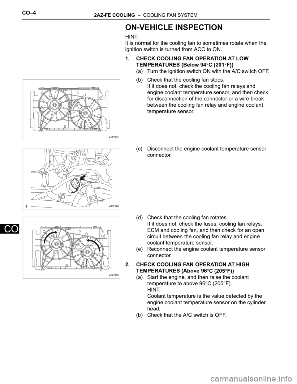
1. CHECK COOLING FAN OPERATION AT LOW
TEMPERATURES (Below 94
C (201F))
(a) Turn the ignition switch ON with the A/C switch OFF.
(b) Check that the cooling fan stops.
If it does not, check the cooling fan relays and
engine coolant temperature sensor, and then check
for disconnection of the connector or a wire break
between the cooling fan relay and engine coolant
temperature sensor.
(c) Disconnect the engine coolant temperature sensor
connector.
(d) Check that the cooling fan rotates.
If it does not, check the fuses, cooling fan relays,
ECM and cooling fan, and then check for an open
circuit between the cooling fan relay and engine
coolant temperature sensor.
(e) Reconnect the engine coolant temperature sensor
connector.
2. CHECK COOLING FAN OPERATION AT HIGH
TEMPERATURES (Above 96
C (205F))
(a) Start the engine, and then raise the coolant
temperature to above 96
C (205F).
HINT:
Coolant temperature is the value detected by the
engine coolant temperature sensor on the cylinder
head.
(b) Check that the A/C switch is OFF.
A127842
A112176
A127843
Page 241 of 2000
2AZ-FE COOLING – COOLING FAN SYSTEMCO–5
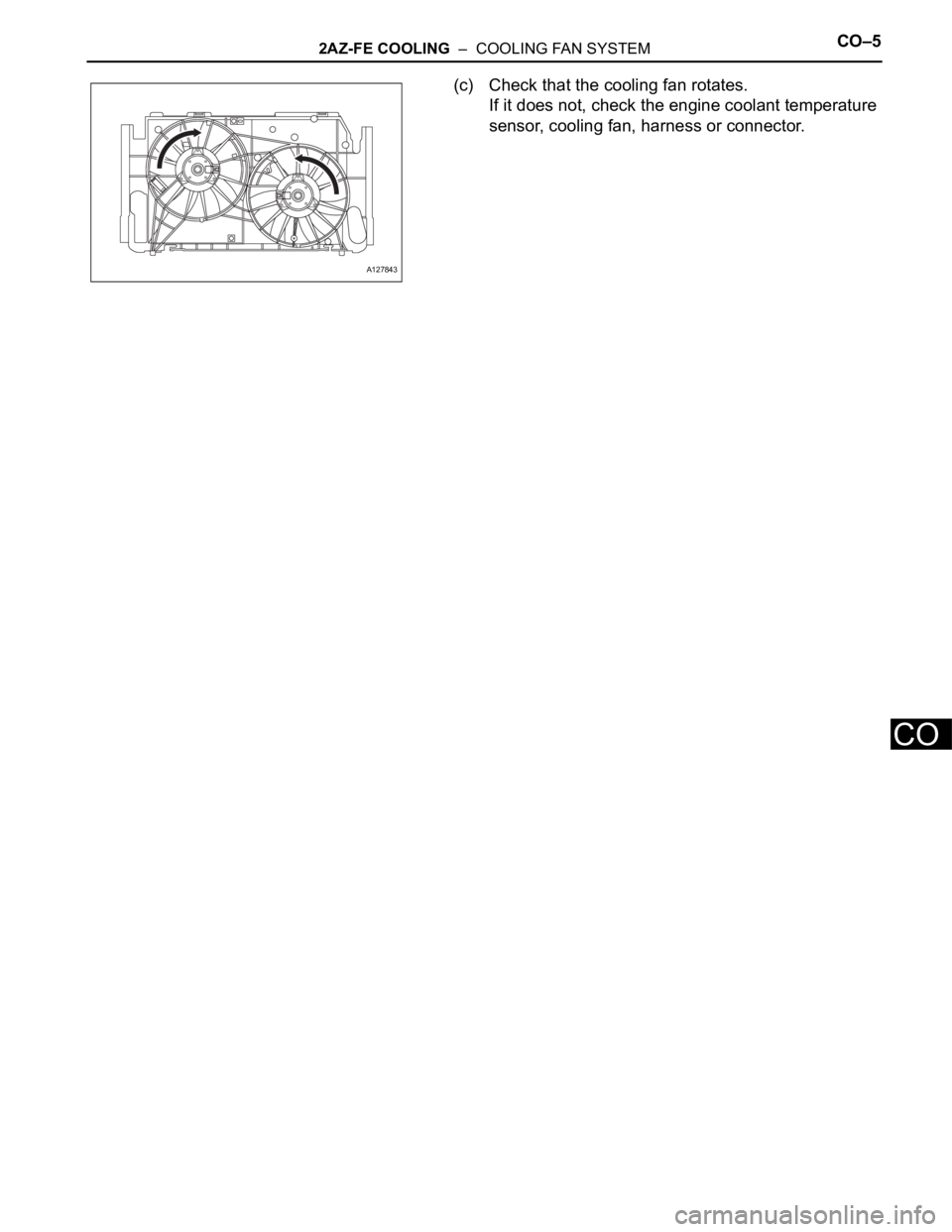
CO
(c) Check that the cooling fan rotates.
If it does not, check the engine coolant temperature
sensor, cooling fan, harness or connector.
A127843
Page 344 of 2000

U140F AUTOMATIC TRANSAXLE – AUTOMATIC TRANSAXLE SYSTEMAX–3
AX
DEFINITION OF TERMS
Te r m D e f i n i t i o n
Monitor description Description of what the ECM monitors and how it detects malfunctions (monitoring purpose and its details).
Related DTCs Diagnostic code.
Typical enabling conditionPreconditions that allow the ECM to detect malfunctions.
With all preconditions satisfied, the ECM sets the DTC when the monitored value(s) exceeds the
malfunction threshold(s).
Sequence of operationThe priority order that is applied to monitoring, if multiple sensors and components are used to detect the
malfunction.
While another sensor is being monitored, the next sensor or component will not be monitored.
Required sensor/Components The sensors and components that are used by the ECM to detect malfunctions.
Frequency of operationThe number of times that the ECM checks for malfunctions per driving cycle.
"Once per driving cycle" means that the ECM detects malfunction only 1 time during a single driving cycle.
"Continuous" means that the ECM detects a malfunction every time the enabling condition is met.
DurationThe minimum time that the ECM must sense a continuous deviation in the monitored value(s) before
setting a DTC. This timing begins after the "typical enabling conditions" are met.
Malfunction thresholds Beyond this value, the ECM will conclude that there is a malfunction and set a DTC.
MIL operationMIL illumination timing after a defect is detected.
"Immediate" means that the ECM illuminates the MIL the instant the ECM determines that there is a
malfunction.
"2 driving cycle" means that the ECM illuminates the MIL if the same malfunction is detected again in the
2nd driving cycle.
Component operating rangeNormal operation range of sensors and solenoids under normal driving conditions.
Use these ranges as a reference.
They cannot be used to judge if a sensor or solenoid is defective or not.