light TOYOTA RAV4 HYBRID 2020 Owners Manual (in English)
[x] Cancel search | Manufacturer: TOYOTA, Model Year: 2020, Model line: RAV4 HYBRID, Model: TOYOTA RAV4 HYBRID 2020Pages: 744, PDF Size: 31.43 MB
Page 646 of 744
6468-2. Steps to take in an emergency
WA R N I N G
■Maintenance of the tires
(vehicles with tire pressure
warning system)
Each tire, including the spare (if
provided), should be checked
monthly when cold and inflated to
the inflation pressure recom-
mended by the vehicle manufac-
turer on the vehicle placard or tire
inflation pressure label (tire and
load information label). (If your
vehicle has tires of a different size
than the size indicated on the
vehicle placard or tire inflation
pressure label [tire and load infor-
mation label], you should deter-
mine the proper tire inflation
pressure for those tires.)
As an added safe ty feature, your
vehicle has been equipped with a
tire pressure m onitoring system
(TPMS-tire pressure warning sys-
tem) that illumina tes a low tire
pressure telltale (tire pressure
warning light) when one or more
of your tires is significantly under-
inflated. Accordingly, when the
low tire pressure telltale (tire pres-
sure warning light) illuminates,
you should stop and check your
tires as soon as possible, and
inflate them to the proper pres-
sure. Driving on a significantly
under-inflated tire causes the tire
to overheat and can lead to tire
failure. Under-inflation also
reduces fuel efficiency and tire
tread life, and may affect the vehi-
cle’s handling and stopping ability.
Please note that the TPMS (tire
pressure warning system) is not a
substitute for pro per tire mainte-
nance, and it is the driver’s
responsibility to m aintain correct
tire pressure, eve n if under-infla-
tion has not reach ed the level to
trigger illuminatio n of the TPMS
low tire pressure telltale (tire pres-
sure warning light).
Your vehicle has also been
equipped with a TPMS (tire pres-
sure warning system) malfunc-
tion indicator to indicate when the
system is not operating properly.
The TPMS (tire pressure warning
system) malfunction indicator is
combined with the low tire pres-
sure telltale (tire pressure warning
light). When the system detects a
malfunction, the te lltale will flash
for approximately one minute and
then remain continuously illumi-
nated. This sequence will con-
tinue upon subsequent vehicle
start-ups as long as the malfunc-
tion exists. When the malfunction
indicator is illu minated, the sys-
tem may not be ab le to detect or
signal low tire pressure as
intended.
TPMS (tire pressure warning sys-
t em ) m alf un ctio n s m a y o cc ur f or a
variety of reasons, including the
installation of replacement or
alternate tires or wheels on the
vehicle that prevent the TPMS
(tire pressure warning system)
from functioning properly. Always
check the TPMS (tire pressure
warning system) malfunction tell-
tale after replacing one or more
tires or wheels on your vehicle to
ensure that the replacement or
alternate tires and wheels allow
the TPMS (tire pressure warning
system) to continue to function
properly.
NOTICE
■To ensure the tire pressure
warning system operates
properly (vehicles with tire
pressure warning system)
Do not install tires with different
specifications or manufacturers
as the tire pressure warning sys-
tem may not operate properly.
Page 647 of 744
6478-2. Steps to take in an emergency
8
When trouble arises■Warning messages
The warning messages explained
below may differ from the actual
messages according to operation
conditions and vehicle specifica-
tions.
■If a message about an operation
is shown
●If a message about an operation
of the accele rator pedal or brake
pedal is shown
A warning message about an opera-
tion of the brake pedal may be shown while the driving assist sys-
tems such as PCS (Pre-Collision
system) or the dynamic radar cruise
control with full-speed range is oper-
ating. If a warning message is
shown, be sure to decelerate the
vehicle or follo
w an instruction
shown on the multi-information dis-
play.
A warning message is shown when
Brake Override System, Drive-Start
Control or Parking Support Brake (if
equipped) (P.190, 297) operates.
Follow the instructions on the multi-
information display.
●If a message about an operation
of the power switch is shown
An instruction for operation of the
power switch is shown when the
incorrect procedure for starting the
hybrid system is performed or the
power switch is operated incorrectly.
Follow the instructions shown on the
multi-information di splay to operate
the power switch again.
●If a message about a shift lever
operation is shown
To prevent the shift lever from being
operated incorrectl y or the vehicle
from moving unexpectedly, a mes-
sage that requires shifting the shift
lever may be shown on the multi-
information displa y. In that case, fol-
low the instructio n of the message
and shift the shift lever.
●If a message or image about an
open/close state of a part or
replenishment of a consumable is
shown
Confirm the part indicated by the
multi-information display or a warn-
ing light, and then perform the cop-
ing method such as closing the
open door or replenishing a con-
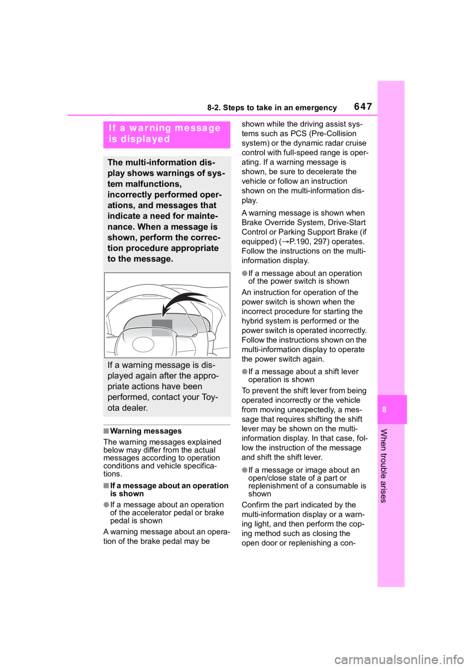
If a war ning message
is displayed
The multi-information dis-
play shows warnings of sys-
tem malfunctions,
incorrectly performed oper-
ations, and messages that
indicate a need for mainte-
nance. When a message is
shown, perform the correc-
tion procedure appropriate
to the message.
If a warning message is dis-
played again after the appro-
priate actions have been
performed, contact your Toy-
ota dealer.
Page 650 of 744
6508-2. Steps to take in an emergency
■If “Radar Cruise Control
Unavailable” is shown
The dynamic radar cruise control
with full-speed range system cannot
be used temporarily. Use the system
when it becomes available again.
■Warning buzzer
P. 6 4 3
WA R N I N G
■If a warning light comes on or
a warning buzzer sounds
when a warning message is
shown on the multi-informa-
tion display
P. 6 4 5
NOTICE
■“High Power Consumption
Partial Limit On AC/Heater
Operation” is frequently
shown
There is a possible malfunction
relating to the ch arging system or
the 12-volt battery may be deteri-
orating. Have the vehicle
inspected by your Toyota dealer.
Page 654 of 744
6548-2. Steps to take in an emergency
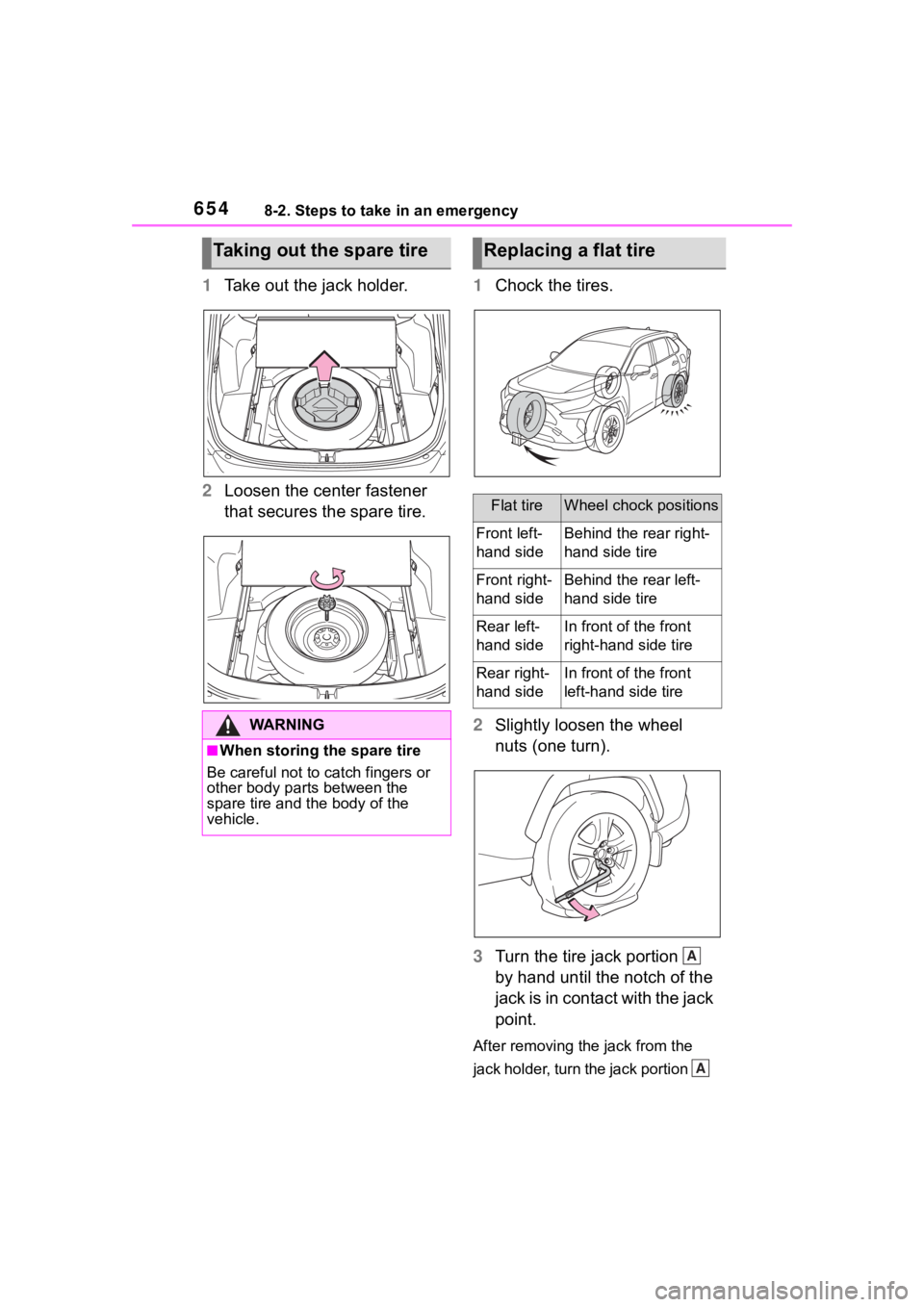
1Take out the jack holder.
2 Loosen the center fastener
that secures the spare tire. 1
Chock the tires.
2 Slightly loosen the wheel
nuts (one turn).
3 Turn the tire jack portion
by hand until the notch of the
jack is in contact with the jack
point.
After removing the jack from the
jack holder, turn the jack portion
Taking out the spare tire
WA R N I N G
■When storing the spare tire
Be careful not to catch fingers or
other body parts between the
spare tire and the body of the
vehicle.
Replacing a flat tire
Flat tireWheel chock positions
Front left-
hand sideBehind the rear right-
hand side tire
Front right-
hand sideBehind the rear left-
hand side tire
Rear left-
hand sideIn front of the front
right-hand side tire
Rear right-
hand sideIn front of the front
left-hand side tire
A
A
Page 655 of 744
6558-2. Steps to take in an emergency
8
When trouble arises
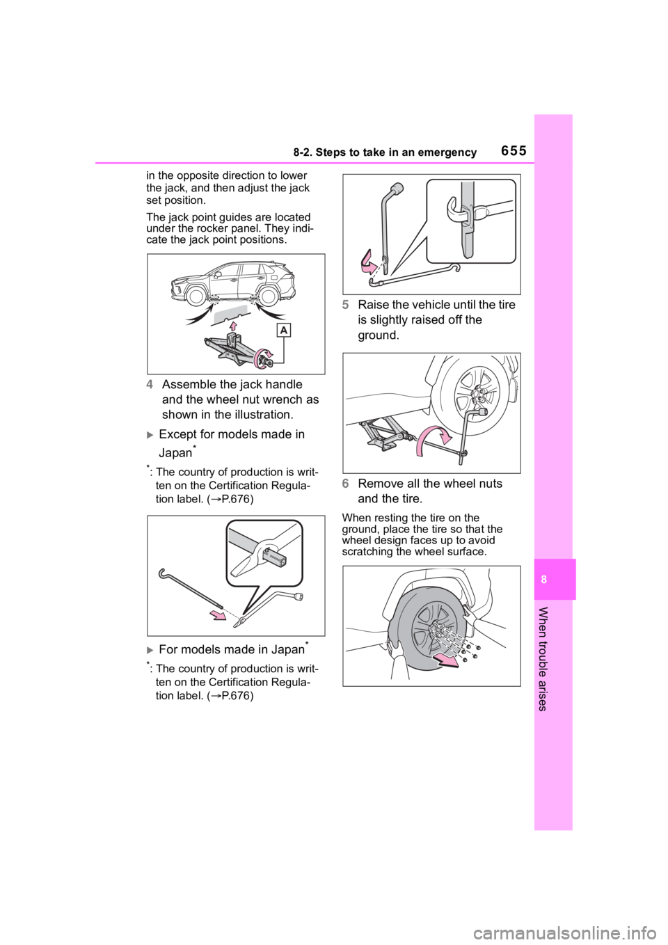
in the opposite direction to lower
the jack, and then adjust the jack
set position.
The jack point guides are located
under the rocker panel. They indi-
cate the jack point positions.
4Assemble the jack handle
and the wheel nut wrench as
shown in the illustration.
Except for models made in
Japan
*
*: The country of production is writ-
ten on the Certification Regula-
tion label. ( P.676)
For models made in Japan*
*: The country of production is writ-
ten on the Certification Regula-
tion label. ( P.676)
5 Raise the vehicle until the tire
is slightly raised off the
ground.
6 Remove all the wheel nuts
and the tire.
When resting the tire on the
ground, place the tire so that the
wheel design faces up to avoid
scratching the wheel surface.
Page 657 of 744
6578-2. Steps to take in an emergency
8
When trouble arises
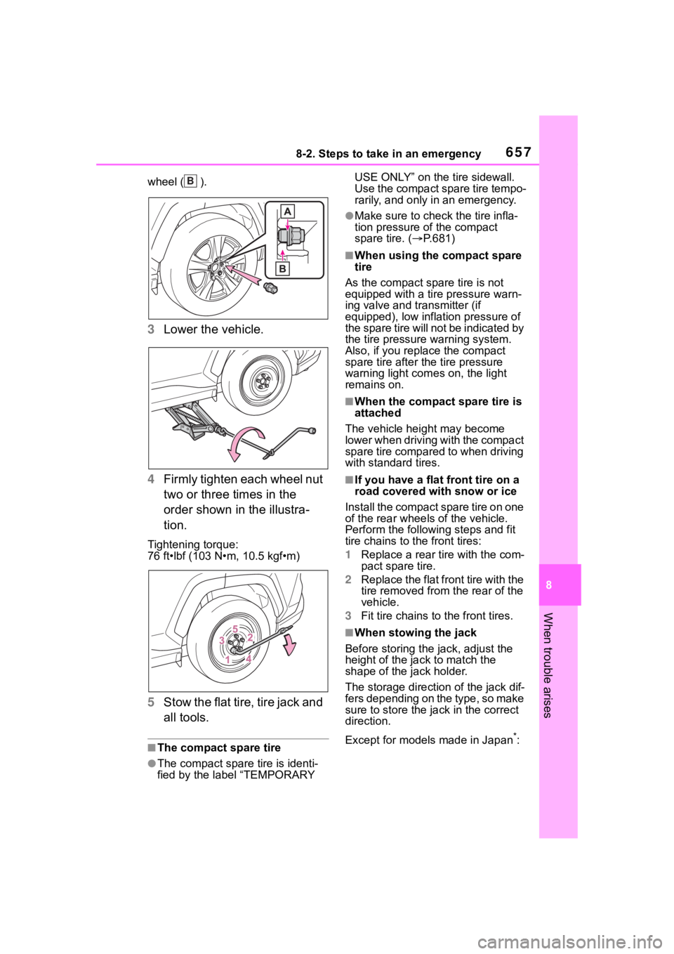
wheel ( ).
3Lower the vehicle.
4 Firmly tighten each wheel nut
two or three times in the
order shown in the illustra-
tion.
Tightening torque:
76 ft•lbf (103 N•m, 10.5 kgf•m)
5Stow the flat tire, tire jack and
all tools.
■The compact spare tire
●The compact spare tire is identi-
fied by the label “TEMPORARY USE ONLY” on the tire sidewall.
Use the compact spare tire tempo-
rarily, and only in an emergency.
●Make sure to check the tire infla-
tion pressure of the compact
spare tire. (
P.681)
■When using the compact spare
tire
As the compact spare tire is not
equipped with a tire pressure warn-
ing valve and transmitter (if
equipped), low inflation pressure of
the spare tire will not be indicated by
the tire pressure warning system.
Also, if you replace the compact
spare tire after the tire pressure
warning light com es on, the light
remains on.
■When the compact spare tire is
attached
The vehicle height may become
lower when driving with the compact
spare tire compared to when driving
with standard tires.
■If you have a flat front tire on a
road covered with snow or ice
Install the compact spare tire on one
of the rear wheels of the vehicle.
Perform the following steps and fit
tire chains to the front tires:
1 Replace a rear tire with the com-
pact spare tire.
2 Replace the flat front tire with the
tire removed from the rear of the
vehicle.
3 Fit tire chains to the front tires.
■When stowing the jack
Before storing the jack, adjust the
height of the ja ck to match the
shape of the jack holder.
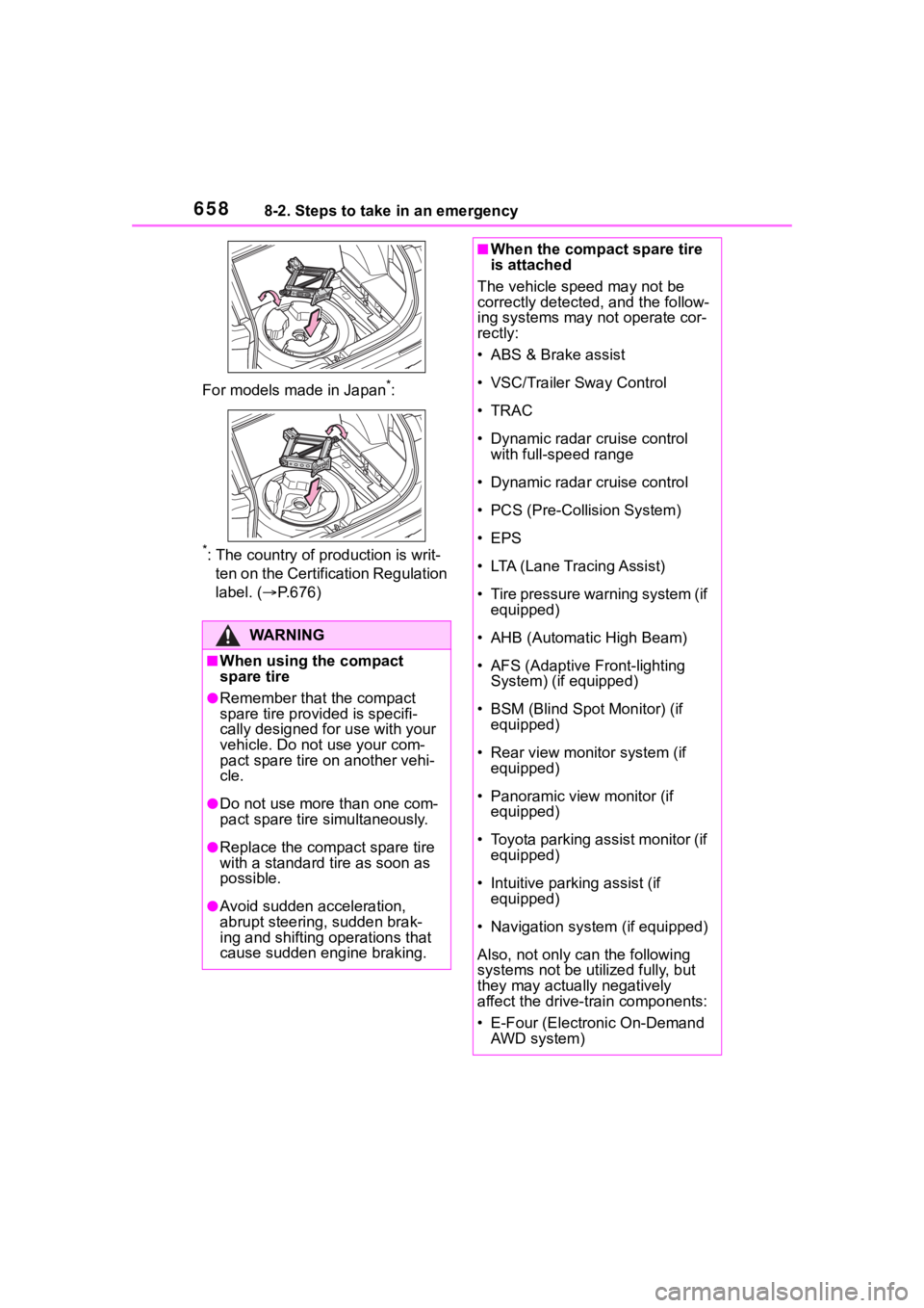
The storage direction of the jack dif-
fers depending on the type, so make
sure to store the ja ck in the correct
direction.
Except for models made in Japan
*:
B
Page 658 of 744
6588-2. Steps to take in an emergency
For models made in Japan*:
*: The country of production is writ-
ten on the Certific ation Regulation
label. ( P.676)
WA R N I N G
■When using the compact
spare tire
●Remember that the compact
spare tire provided is specifi-
cally designed for use with your
vehicle. Do not use your com-
pact spare tire on another vehi-
cle.
●Do not use more than one com-
pact spare tire simultaneously.
●Replace the compact spare tire
with a standard tire as soon as
possible.
●Avoid sudden acceleration,
abrupt steering, sudden brak-
ing and shifting operations that
cause sudden engine braking.
■When the compact spare tire
is attached
The vehicle speed may not be
correctly detected, and the follow-
ing systems may not operate cor-
rectly:
• ABS & Brake assist
• VSC/Trailer Sway Control
•TRAC
• Dynamic radar cruise control with full-speed range
• Dynamic radar cruise control
• PCS (Pre-Collision System)
• EPS
• LTA (Lane Tracing Assist)
• Tire pressure warning system (if equipped)
• AHB (Automatic High Beam)
• AFS (Adaptive Front-lighting System) (if equipped)
• BSM (Blind Spot Monitor) (if equipped)
• Rear view monitor system (if equipped)
• Panoramic view monitor (if equipped)
• Toyota parking assist monitor (if equipped)
• Intuitive parking assist (if equipped)
• Navigation system (if equipped)
Also, not only c an the following
systems not be utilized fully, but
they may actually negatively
affect the drive-train components:
• E-Four (Electronic On-Demand
AWD system)
Page 660 of 744
6608-2. Steps to take in an emergency
One of the following may be the
cause of the problem:
The electronic key may not be
functioning properly.
( P.663)
There may not be sufficient
fuel in the vehicle’s tank.
Refuel the vehicle. ( P.240)
There may be a malfunction
in the immobilizer system.
( P. 8 2 )
There may be a malfunction
in the steering lock system.
The hybrid system may be
malfunctioning due to an elec-
trical problem such as elec-
tronic key battery depletion or
a blown fuse. However,
depending on the type of mal-
function, an interim measure
is available to start the hybrid
system. ( P.660) One of the following may be the
cause of the problem:
The 12-volt battery may be
discharged. ( P.665)
The 12-volt battery terminal
connections may be loose or
corroded. ( P.586)
One of the following may be the
cause of the problem:
The 12-volt battery may be
discharged. ( P.665)
One or both of the 12-volt bat-
tery terminals may be discon-
nected. ( P.586)
Contact your Toyota dealer if the
problem cannot be repaired, or if
repair procedures are unknown.
When the hybrid system does
not start, the following steps can
be used as an interim measure
to start the hybrid system if the
power switch is functioning nor-
mally.
If the hybrid system
will not start
Reasons for the hybrid sys-
tem not starting vary
depending on the situation.
Check the following and
perform the appropriate
procedure:
The hybrid system will not
start even though the cor-
rect starting procedure is
being followed ( P.210,
212)
The interior lights and
headlights are dim, or the
horn does not sound or
sounds at a low volume
The interior lights and
headlights do not turn on,
or the horn does not
sound
Starting the hybrid sys-
tem in an emergency
Page 666 of 744
6668-2. Steps to take in an emergency
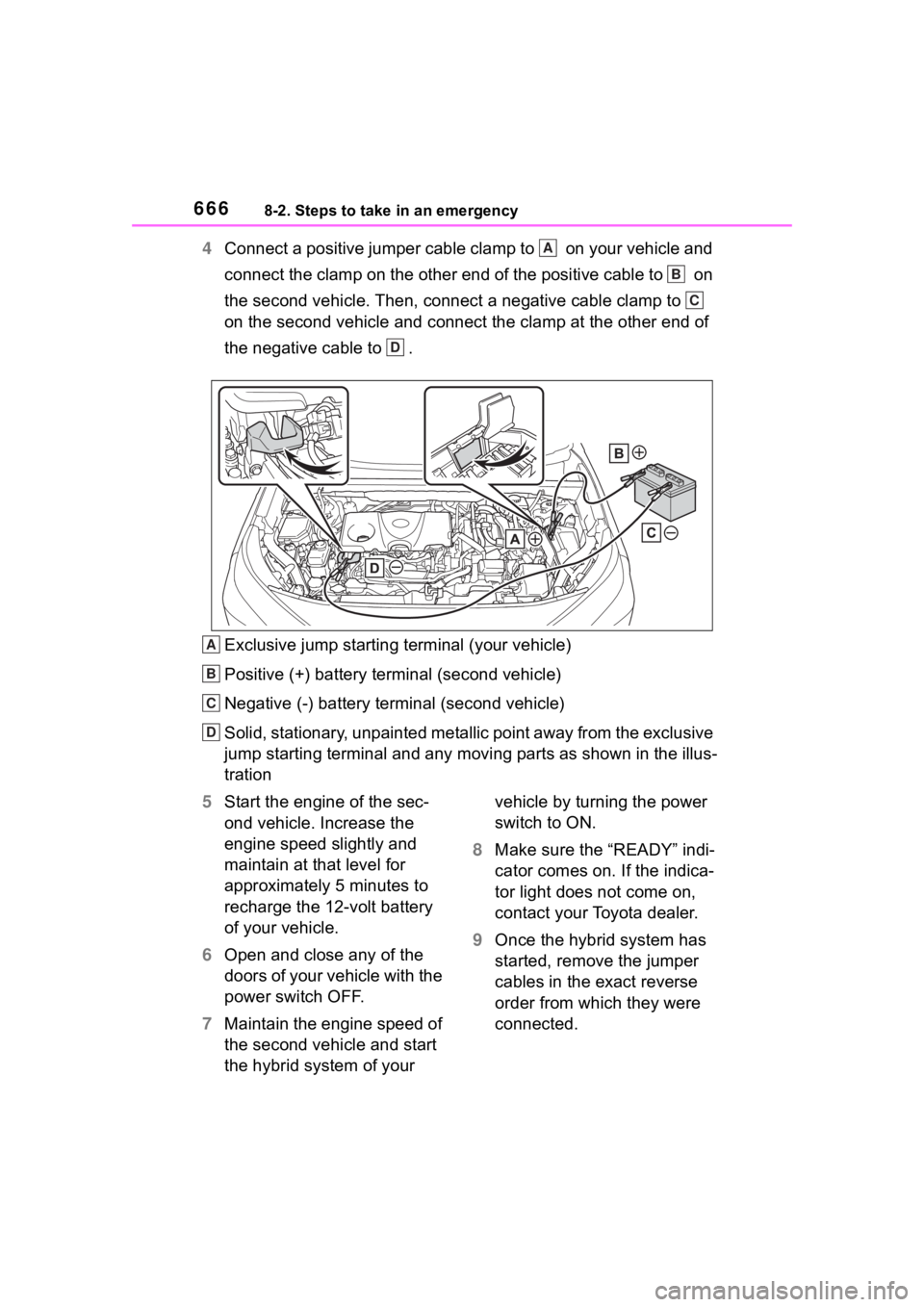
4Connect a positive jumper cable clamp to on your vehicle and
connect the clamp on the other end of the positive cable to on
the second vehicle. Then, connect a negative cable clamp to
on the second vehicle and connect the clamp at the other end of
the negative cable to .
Exclusive jump starting terminal (your vehicle)
Positive (+) battery terminal (second vehicle)
Negative (-) battery term inal (second vehicle)
Solid, stationary, unpainted metallic point away from the exclu sive
jump starting terminal and any m oving parts as shown in the illus-
tration
5 Start the engine of the sec-
ond vehicle. Increase the
engine speed slightly and
maintain at that level for
approximately 5 minutes to
recharge the 12-volt battery
of your vehicle.
6 Open and close any of the
doors of your vehicle with the
power switch OFF.
7 Maintain the engine speed of
the second vehicle and start
the hybrid system of your vehicle by turning the power
switch to ON.
8 Make sure the “READY” indi-
cator comes on. If the indica-
tor light does not come on,
contact your Toyota dealer.
9 Once the hybrid system has
started, remove the jumper
cables in the exact reverse
order from which they were
connected.A
B
C
D
A
B
C
D
Page 667 of 744
6678-2. Steps to take in an emergency
8
When trouble arises
10Close the exclusive jump
starting terminal cover, and
reinstall the fuse box cover to
its original position.
Once the hybrid system starts,
have the vehicle inspected at
your Toyota dealer as soon as
possible.
■Starting the hybrid system
when the 12-volt battery is dis-
charged
The hybrid system cannot be started
by push-starting.
■To prevent 12-volt battery dis-
charge
●Turn off the headlights and the
audio system while the hybrid sys-
tem is off.
●Turn off any unnecessary electri-
cal components when the vehicle
is running at a low speed for an
extended period, such as in heavy
traffic.
■When the 12-volt battery is
removed or discharged
●Information stor ed in the ECU is
cleared. When the 12-volt battery
is depleted, have the vehicle
inspected at you r Toyota dealer.
●Some systems may require initial-
ization. ( P.708)
■When removing the 12-volt bat-
tery terminals
When the 12-volt battery terminals
are removed, the information stored
in the ECU is cleared. Before
removing the 12-volt battery termi-
nals, contact your Toyota dealer.
■Charging the 1 2-volt battery
The electricity stor ed in the 12-volt
battery will discharge gradually even
when the vehicle is not in use, due
to natural discharge and the drain-
ing effects of certain electrical appli-
ances. If the vehicle is left for a long time, the 12-volt
battery may dis-
charge, and the hybrid system may
be unable to start. (The 12-volt bat-
tery recharges automatically while
the hybrid system is operating.)
■When recharging or replacing
the 12-volt battery (vehicles
without smart key system)
The hybrid system may not start on
the first attempt after the 12-volt bat-
tery has recharged but will start nor-
mally after the second attempt. This
is not a malfunction.
■When recharging or replacing
the 12-volt battery (vehicles
with smart key system)
●In some cases, it may not be pos-
sible to unlock the doors using the
smart key system when the 12-
volt battery is discharged. Use the
wireless remote c ontrol or the
mechanical key to lock or unlock
the doors.
●The hybrid syste m may not start
on the first attempt after the 12-
volt battery has recharged but will
start normally after the second
attempt. This is not a malfunction.
●The power switch mode is memo-
rized by the vehicle. When the 12-
volt battery is reconnected, the
system will return to the mode it
was in before the 12-volt battery
was discharged. Before discon-
necting the 12-volt battery, turn
the power switch off.
If you are unsure what mode the
power switch was in before the
12-volt battery discharged, be
especially careful when recon-
necting the 12-volt battery.
●Some systems may require initial-
ization. ( P.708)
■When replacing t he 12-volt bat-
tery
●Use a 12-volt battery that con-
forms to European regulations.
●Ty p e A :
Use a battery that the case size is