navigation system TOYOTA RAV4 PLUG-IN HYBRID 2021 Owners Manual
[x] Cancel search | Manufacturer: TOYOTA, Model Year: 2021, Model line: RAV4 PLUG-IN HYBRID, Model: TOYOTA RAV4 PLUG-IN HYBRID 2021Pages: 666, PDF Size: 161.28 MB
Page 18 of 666
16Pictorial index
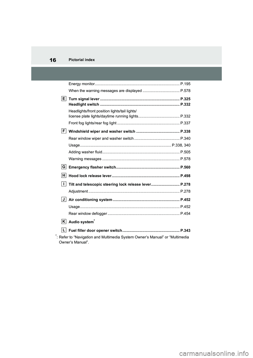
Energy monitor................................................. ............................... P.195
When the warning messages are displayed ................................... P.578
Turn signal lever .............................................. ............................. P.325
Headlight switch ............................................... ............................ P.332
Headlights/front posit ion lights/tail lights/
license plate lights/daytime r unning lights....................................... P.332
Front fog lights/rear fog light ................................ ........................... P.337
Windshield wiper and washer switch ............................. ............ P.338
Rear window wiper and washer switch ............................ ............... P.340
Usage.......................................................... ............................ P.338, 340
Adding washer fluid............................................ ............................. P.505
Warning messages ............................................... .......................... P.578
Emergency flasher switch....................................... ..................... P.560
Hood lock release lever .... ............................................................ P.498
Tilt and telescopic steering lock release lever................ ........... P.278
Adjustment ..................................................... ................................. P.278
Air conditioning system ........................................ ....................... P.452
Usage.......................................................... .................................... P.452
Rear window defogger ........................................... ......................... P.454
Audio system*
Fuel filler door opener switch ................................. ..................... P.343
*: Refer to “Navigation and Multimedia System Owner’s Manual” or “Multimedia
Owner’s Manual”.
E
F
G
H
I
J
K
L
Page 19 of 666
17Pictorial index
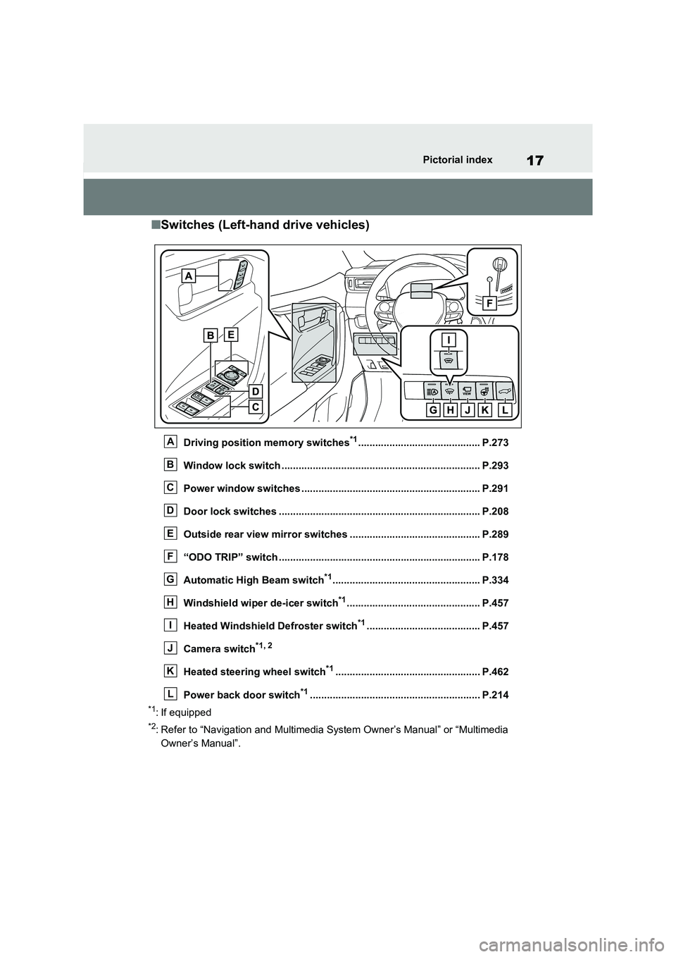
■Switches (Left-hand drive vehicles)
Driving position memory switches*1........................................... P.273
Window lock switch ............................................. ......................... P.293
Power window switches .......................................... ..................... P.291
Door lock switches ............................................. .......................... P.208
Outside rear view mirror switches .............................. ................ P.289
“ODO TRIP” switch .............................................. ......................... P.178
Automatic High Beam switch*1.................................................... P.334
Windshield wiper de-icer switch*1............................................... P.457
Heated Windshield Defroster switch*1........................................ P.457
Camera switch*1, 2
Heated steering wheel switch*1................................................... P.462
Power back door switch*1............................................................ P.2 14
*1: If equipped
*2: Refer to “Navigation and Multimedia System Owner’s Manual” or “Multimedia
Owner’s Manual”.
A
B
C
D
E
F
G
H
I
J
K
L
Page 20 of 666
18Pictorial index
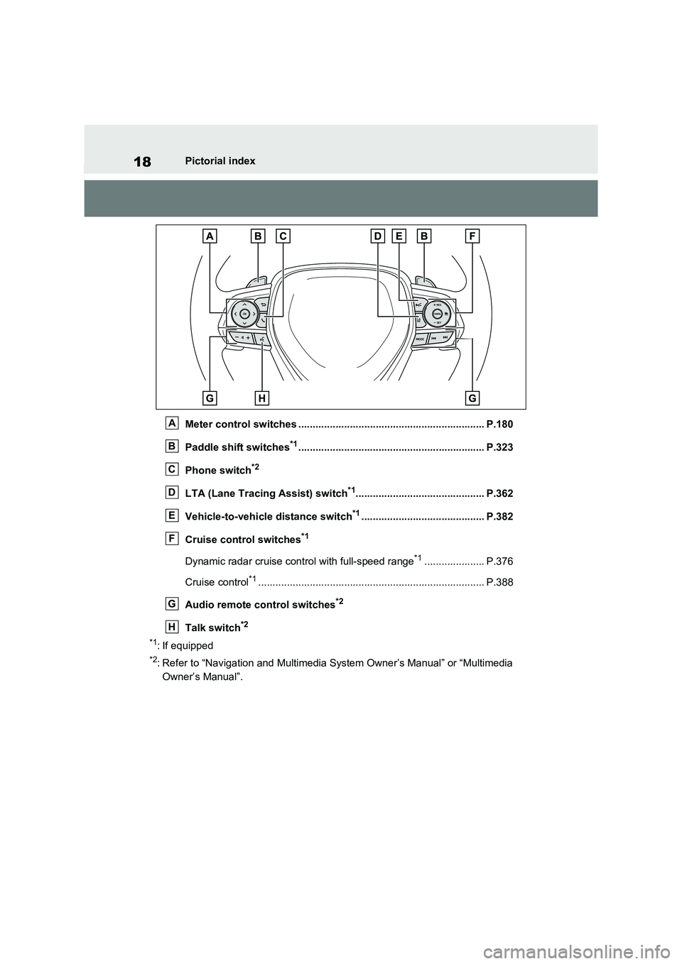
Meter control switc hes ................................................................. P.180
Paddle shift switches*1............................................................... .. P.323
Phone switch*2
LTA (Lane Tracing Assist) switch*1............................................. P.362
Vehicle-to-vehicle distance switch*1........................................... P.382
Cruise control switches*1
Dynamic radar cruise cont rol with full-speed range*1..................... P.376
Cruise control*1............................................................... ................ P.388
Audio remote control switches*2
Talk switch*2
*1: If equipped
*2: Refer to “Navigation and Multimedia System Owner’s Manual” or “Multimedia
Owner’s Manual”.
A
B
C
D
E
F
G
H
Page 26 of 666

24Pictorial index
Energy monitor................................................. ............................... P.195
When the warning messages are displayed ................................... P.578
Turn signal lever .............................................. ............................. P.325
Headlight switch ............................................... ............................ P.332
Headlights/front posit ion lights/tail lights/
license plate lights/daytime r unning lights....................................... P.332
Front fog lights/rear fog light ................................ ........................... P.337
Windshield wiper and washer switch ............................. ............ P.338
Rear window wiper and washer switch ............................ ............... P.340
Usage.......................................................... ............................ P.338, 340
Adding washer fluid............................................ ............................. P.505
Warning messages ............................................... .......................... P.578
Emergency flasher switch....................................... ..................... P.560
Hood lock release lever .... ............................................................ P.498
Tilt and telescopic steering control lever ..................... .............. P.278
Adjustment ..................................................... ................................. P.278
Air conditioning system ........................................ ....................... P.452
Usage.......................................................... .................................... P.452
Rear window defogger ........................................... ......................... P.454
Audio system*
Fuel filler door opener switch ................................. ..................... P.343
*: Refer to “Navigation and Multimedia System Owner’s Manual” or “Multimedia
Owner’s Manual”.
E
F
G
H
I
J
K
L
Page 27 of 666
25Pictorial index
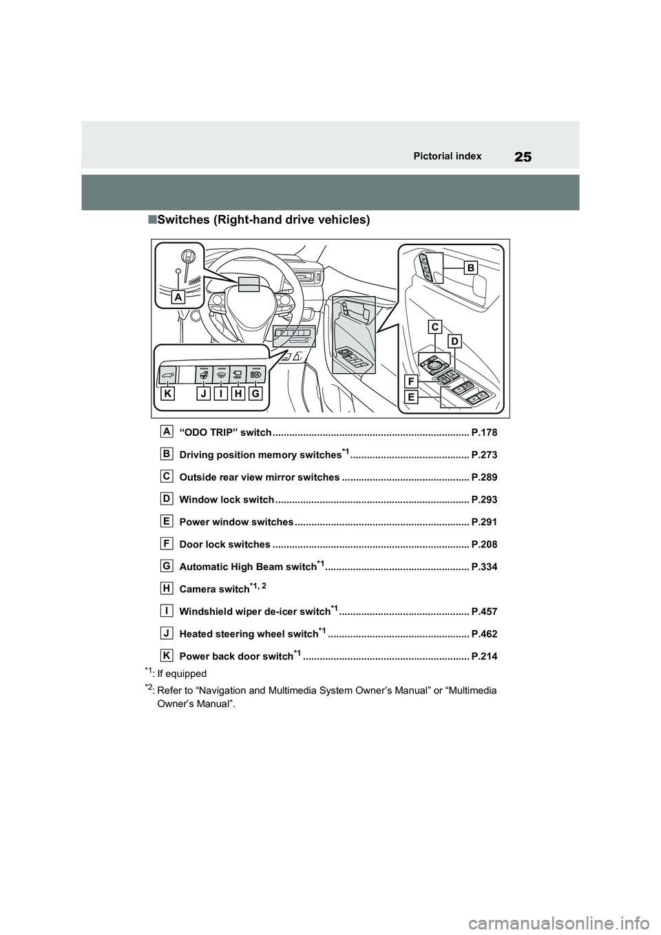
■Switches (Right-hand drive vehicles)
“ODO TRIP” switch ....................................................................... P.178
Driving position memory switches*1........................................... P.273
Outside rear view mirror switches .............................. ................ P.289
Window lock switch ............................................. ......................... P.293
Power window switches .......................................... ..................... P.291
Door lock switches ............................................. .......................... P.208
Automatic High Beam switch*1.................................................... P.334
Camera switch*1, 2
Windshield wiper de-icer switch*1............................................... P.457
Heated steering wheel switch*1................................................... P.462
Power back door switch*1............................................................ P.2 14
*1: If equipped
*2: Refer to “Navigation and Multimedia System Owner’s Manual” or “Multimedia
Owner’s Manual”.
A
B
C
D
E
F
G
H
I
J
K
Page 28 of 666
26Pictorial index
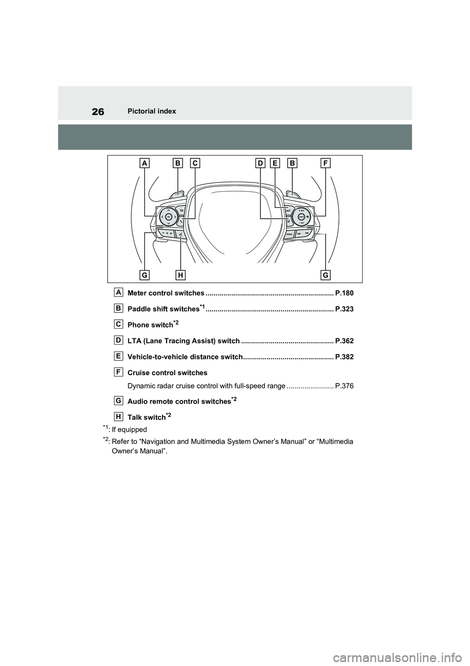
Meter control switc hes ................................................................. P.180
Paddle shift switches*1............................................................... .. P.323
Phone switch*2
LTA (Lane Tracing Assist) switch ............................... ................ P.362
Vehicle-to-vehicle distance switch.............................................. P.382
Cruise control switches
Dynamic radar cruise control wit h full-speed range ........................ P.376
Audio remote control switches*2
Talk switch*2
*1: If equipped
*2: Refer to “Navigation and Multimedia System Owner’s Manual” or “Multimedia
Owner’s Manual”.
A
B
C
D
E
F
G
H
Page 67 of 666
65
1
1-3. Emergency assistance
For safety and security
1-3.Emergency assistance
*: Operates within the eCall coverage.
The system name differs depending
on the country.
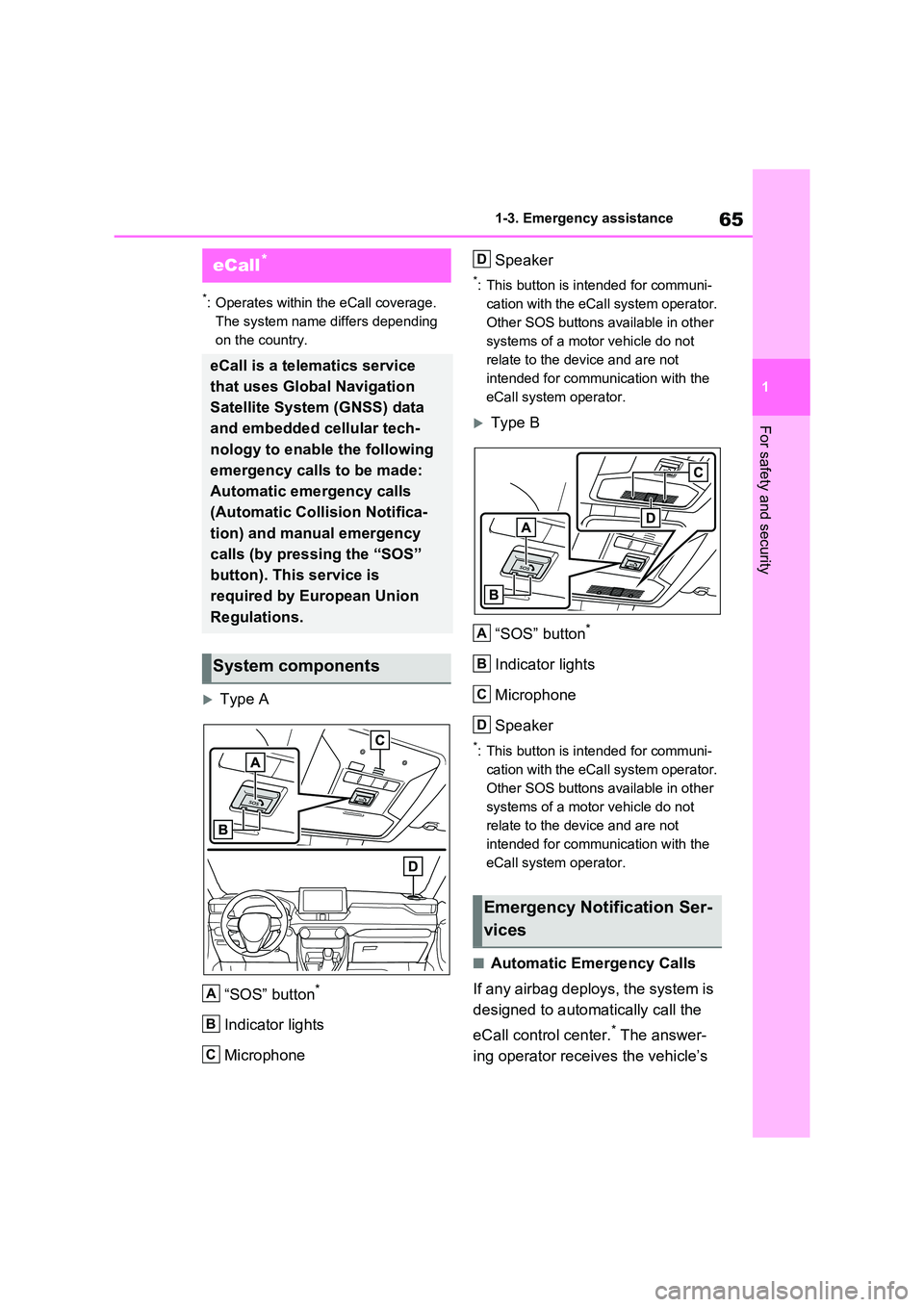
Type A
“SOS” button*
Indicator lights
Microphone
Speaker
*: This button is intended for communi -
cation with the eCal l system operator.
Other SOS buttons available in other
systems of a motor vehicle do not
relate to the dev ice and are not
intended for communication with the
eCall system operator.
Type B
“SOS” button*
Indicator lights
Microphone
Speaker
*: This button is intended for communi -
cation with the eCal l system operator.
Other SOS buttons available in other
systems of a motor vehicle do not
relate to the dev ice and are not
intended for communication with the
eCall system operator.
■Automatic Emergency Calls
If any airbag deploys, the system is
designed to automatically call the
eCall control center.* The answer -
ing operator receives the vehicle’s
eCall*
eCall is a telematics service
that uses Global Navigation
Satellite System (GNSS) data
and embedded cellular tech -
nology to enable the following
emergency calls to be made:
Automatic emergency calls
(Automatic Collision Notifica -
tion) and manual emergency
calls (by pressing the “SOS”
button). This service is
required by European Union
Regulations.
System components
A
B
C
Emergency Notification Ser -
vices
D
A
B
C
D
Page 176 of 666
1743-1. Instrument cluster
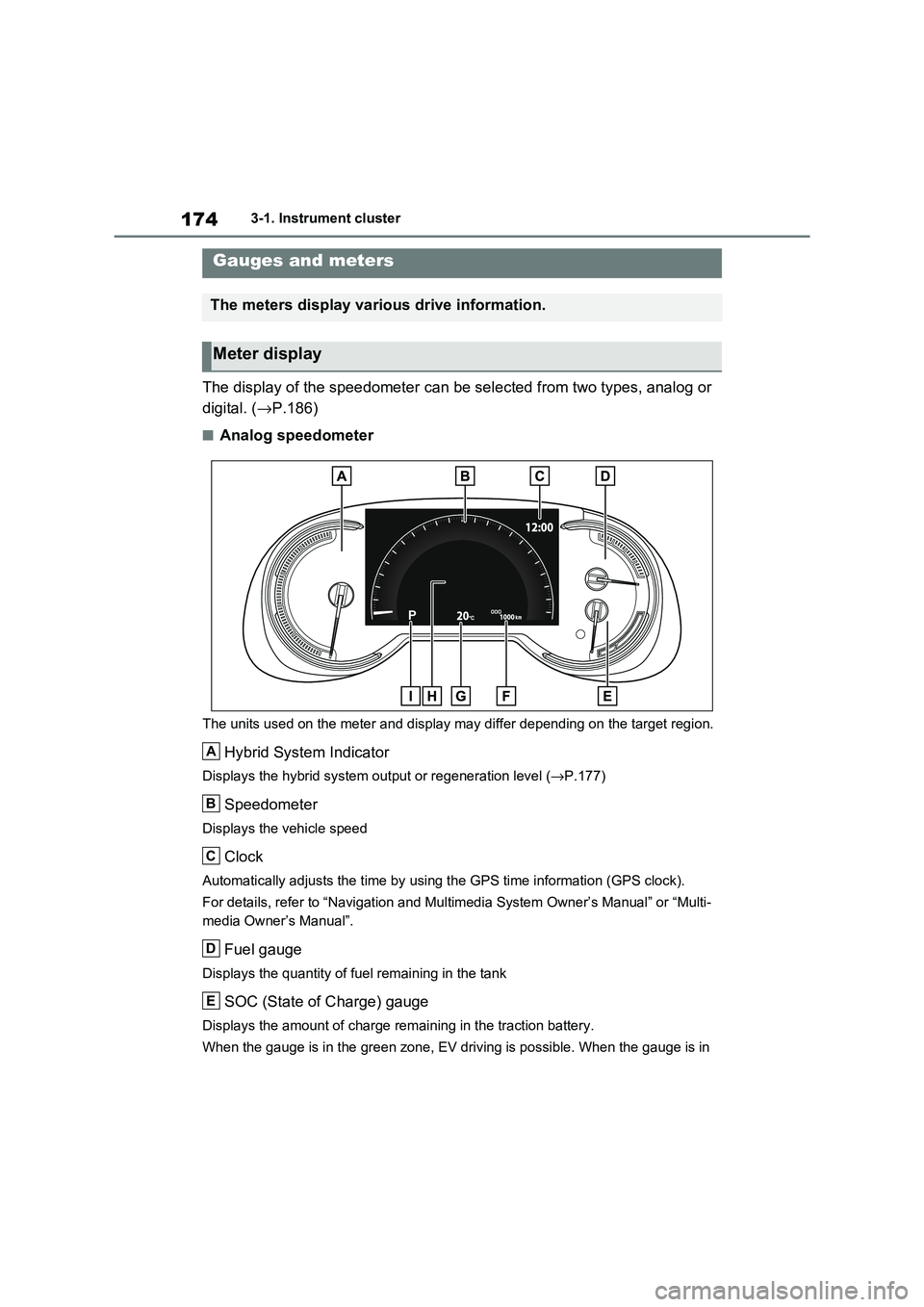
The display of the speedometer can be selected from two types, analog or
digital. ( →P.186)
■Analog speedometer
The units used on the meter and display may differ depending on the target region.
Hybrid System Indicator
Displays the hybrid system output or regeneration level (→P.177)
Speedometer
Displays the vehicle speed
Clock
Automatically adjusts the time by using the GPS time information (GPS clock).
For details, refer to “Navigation and Multimedia System Owner’s Manual” or “Multi-
media Owner’s Manual”.
Fuel gauge
Displays the quantity of f uel remaining in the tank
SOC (State of Charge) gauge
Displays the amount of charge remaining in the traction battery.
When the gauge is in t he green zone, EV driving is possible. When the gauge is in
Gauges and meters
The meters display various drive information.
Meter display
A
B
C
D
E
Page 178 of 666
1763-1. Instrument cluster
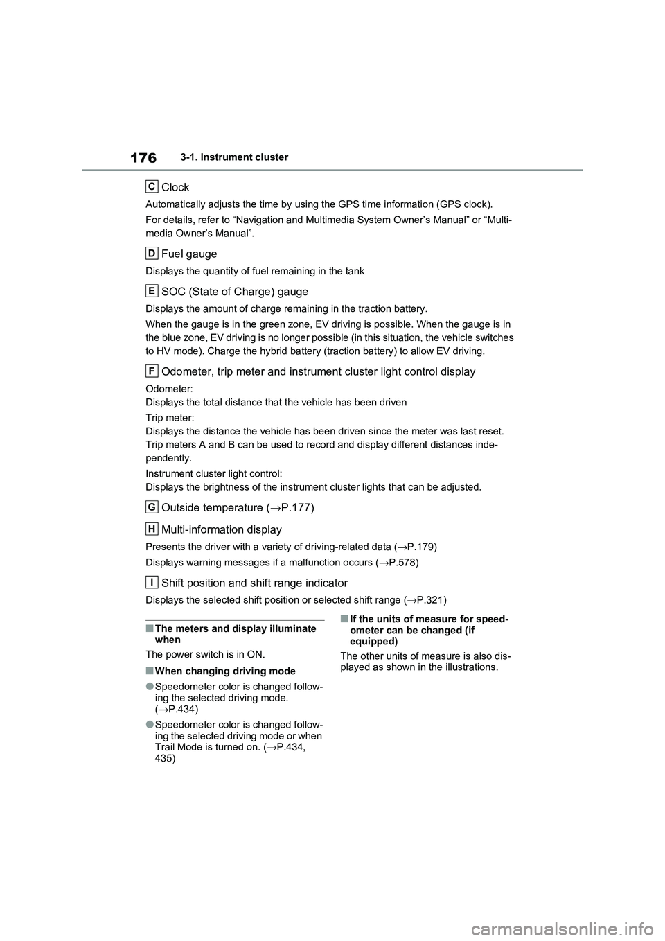
Clock
Automatically adjusts the time by using the GPS time information (GPS clock).
For details, refer to “Navigation and Multimedia System Owner’s Manual” or “Multi-
media Owner’s Manual”.
Fuel gauge
Displays the quantity of f uel remaining in the tank
SOC (State of Charge) gauge
Displays the amount of charge remaining in the traction battery.
When the gauge is in t he green zone, EV driving is possible. When the gauge is in
the blue zone, EV driving is no longer possible (in this situat ion, the vehicle switches
to HV mode). Charge the hybrid ba ttery (traction battery) to allow EV driving.
Odometer, trip meter and instrument cluster light control display
Odometer:
Displays the total distance tha t the vehicle has been driven
Trip meter:
Displays the distance t he vehicle has been driven since the meter was last reset.
Trip meters A and B can be us ed to record and display different distances inde-
pendently.
Instrument cluster light control:
Displays the brightne ss of the instrument cluster lights that can be adjusted.
Outside temperature (→P.177)
Multi-information display
Presents the driver with a variety of driving-related data ( →P.179)
Displays warning messages if a malfunction occurs ( →P.578)
Shift position and shift range indicator
Displays the selected shift position or selected shift range (→P.321)
■The meters and display illuminate when
The power switch is in ON.
■When changing driving mode
●Speedometer color is changed follow -
ing the selected driving mode.
( →P.434)
●Speedometer color is changed follow-
ing the selected driving mode or when Trail Mode is turned on. ( →P.434,
435)
■If the units of measure for speed -
ometer can be changed (if equipped)
The other units of me asure is also dis-
played as shown in the illustrations.
C
D
E
F
G
H
I
Page 181 of 666
179
3
3-1. Instrument cluster
Vehicle status information and indicators
adjusted individually. However, when
the surroundings are bright (daytime, etc.), turning on the tail lights will not
change the instrument cluster bright -
ness.
The clock can be adjusted on the
navigation/multimedia system.
Refer to “Navigation and multime -
dia system Owner’s manual” or
“Multimedia Owner’s Manual”.
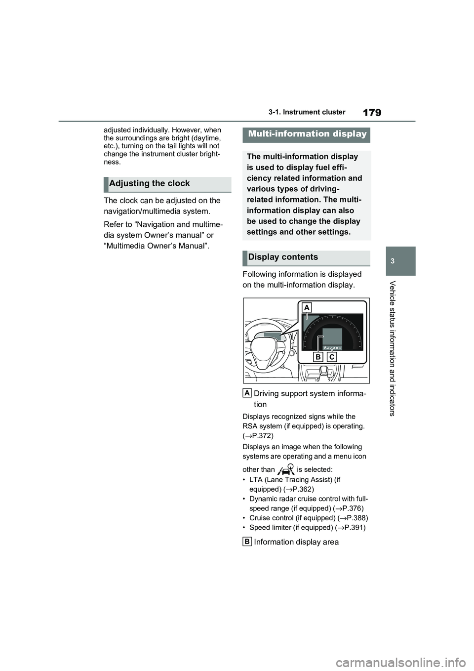
Following information is displayed
on the multi-information display.
Driving support system informa -
tion
Displays recognized signs while the
RSA system (if equ ipped) is operating.
( →P.372)
Displays an image when the following
systems are operating and a menu icon
other than is selected:
• LTA (Lane Tracing Assist) (if
equipped) ( →P.362)
• Dynamic radar cruise control with full-
speed range (if equipped) ( →P.376)
• Cruise control (if equipped) (→P.388)
• Speed limiter (if equipped) ( →P.391)
Information display area
Adjusting the clock
Multi-information display
The multi-information display
is used to display fuel effi -
ciency related information and
various types of driving-
related informat ion. The multi-
information display can also
be used to change the display
settings and other settings.
Display contents
A
B