navigation system TOYOTA RAV4 PLUG-IN HYBRID 2021 User Guide
[x] Cancel search | Manufacturer: TOYOTA, Model Year: 2021, Model line: RAV4 PLUG-IN HYBRID, Model: TOYOTA RAV4 PLUG-IN HYBRID 2021Pages: 666, PDF Size: 161.28 MB
Page 182 of 666
1803-1. Instrument cluster
A variety of infor mation can be dis-
played by selecting a menu icon.
Additionally, warning or sugges -
tion/advice pop-up displays will be dis-
played in some situations.
Menu icons ( →P.180)
■The multi-information display is
displayed when
The power switch is in ON.
■When changing driving mode
●Background color of the multi-informa -
tion display is changed following the selected driving mode. ( →P.434)
●Background color of the multi-informa- tion display is changed following the
selected driving mode or when Trail
Mode is turned on. ( →P.434, 435)
■Liquid crystal display
Small spots or light spots may appear
on the display. This phenomenon is
characteristic of liqui d crystal displays, and there is no prob lem continuing to
use the display.
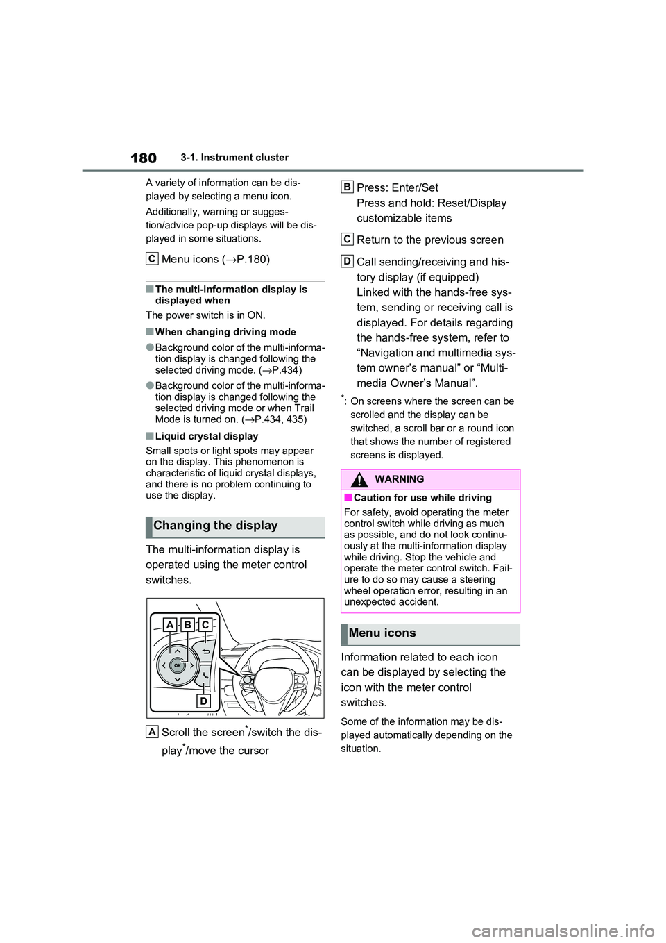
The multi-information display is
operated using the meter control
switches.
Scroll the screen*/switch the dis -
play*/move the cursor
Press: Enter/Set
Press and hold: Reset/Display
customizable items
Return to the previous screen
Call sending/receiving and his -
tory display (if equipped)
Linked with the hands-free sys -
tem, sending or re ceiving call is
displayed. For details regarding
the hands-free system, refer to
“Navigation and multimedia sys -
tem owner’s manual” or “Multi -
media Owner’s Manual”.
*: On screens where the screen can be
scrolled and the display can be
switched, a scroll bar or a round icon
that shows the num ber of registered
screens is displayed.
Information related to each icon
can be displayed by selecting the
icon with the meter control
switches.
Some of the information may be dis -
played automatically depending on the
situation.
Changing the display
C
A
�:�$�5�1�,�1�*
■Caution for use while driving
For safety, avoid o perating the meter
control switch while driving as much
as possible, and do not look continu - ously at the multi-in formation display
while driving. Stop the vehicle and
operate the meter control switch. Fail - ure to do so may cause a steering
wheel operation error, resulting in an
unexpected accident.
Menu icons
B
C
D
Page 186 of 666
1843-1. Instrument cluster
Electricity consumption is the consump -
tion rate of the electricity when EV driv - ing is performed and equivalent to the
fuel consumption for the gasoline vehi -
cles. For this vehic le, electricity con- sumed per 100 km (“kWh/100 km”) is
displayed as electri city consumption on
each screen.
When the unit is set to “MPH” (if
equipped):
Electricity consumption is the consump - tion rate of the electricity when EV driv -
ing is performed and equivalent to the
fuel consumption for the gasoline vehi - cles. For this vehicle, driven distance
per kWh of electricity consumed
(“miles/kWh”) is displ ayed as electricity consumption on each screen.
■EV driving range
●When the air cond itioning system is
operating, is displayed next to
the EV driving range and the EV driv - ing range with the air conditioning sys -
tem on is displayed.
●The EV driving range may shorten
even when not driving due to power
consumption by the system.
●For details, refer to “EV driving range”
( →P.102)
■Distance to empty
●This distance is computed based on
your average fuel consumption. As a result, the actual di stance that can be
driven may differ from that displayed.
●When only a small amount of fuel is
added to the tank, the display may not
be updated. When refueling, turn the power switch off. If the vehicle is refu -
eled without turning the power switch
off, the display may not be updated.
●When “Refuel” is displayed, the
remaining fuel amount is low and the distance that can be driven with the
remaining fuel cannot be calculated.
Refuel immediately.
■ECO Accelerator G uidance/“Eco Score” will not operate when
The ECO Acce lerator Guidance/“Eco
Score” will not operate in the following
situations:
●The Hybrid System I ndicator is not
operating.
●The vehicle is being driven using the
dynamic radar cruise control with full- speed range.
■Driving support system infor -
mation display
Select to display the operational
status of the following systems:
LTA (Lane Tracing Assist)*
( →P.362)
Dynamic radar cruise control
with full-speed range* ( →P.376)
Cruise control* (→P.388)
Speed limiter* (→P.391)
*: If equipped
■Navigation system-linked dis-
play (if equipped)
Select to display the following navi-
gation system-linked information.
Route guidance
Compass display
Select to enable selection of an
audio source or track on the dis -
play.
Driving support system
information display
Audio system-linked display
Page 191 of 666
189
3
3-1. Instrument cluster
Vehicle status information and indicators
• “Drive Info Type”
Select to change the drive information
type display between trip and total.
( →P.185).
• “Drive Info Items”
Select to set the items on the upper and
lower side of the drive information
screen from three items, average
speed, distance and total time.
“Closing Display”
Select to set the items displayed when
the power switch is turned off.
“Pop-Up Display” (if equipped)
Select to enable/disable the following
pop-up displays, which may appear in
some situations.
• Intersection guidance display of the
navigation system-linked system (if
equipped)
• Incoming call disp lay of the hands-
free phone system (if equipped)
• Audio operation
• Volume operation
• Voice control (if equipped)
“Calender”
Select to set up the calender.
This can only be set if GPS calibration
of clock is turned off in the multimedia
system settings.
“MID OFF”
A blank screen is displayed
“Default Settings”
Select to reset the meter display set-
tings.
■Suspension of the settings display
●In the following situations, operation of
the settings display will be temporarily suspended.
• When a warning message appears on
the multi-information display
• When the vehicle begins to move
●Settings for functions not equipped to
the vehicle are not displayed.
●When a function is turned off, the
related settings for that function are not selectable.
Select to display warning mes -
sages and measures to be taken if
a malfunction is detected.
( →P.578)
Displays suggestions to the driver
in the following situations. To select
a response to a displayed sugges -
tion, use the meter control
switches.
WARNING
■Cautions during setting up the
display
As the hybrid system needs to be operating during setting up the dis -
play, ensure that the vehicle is parked
in a place with adequate ventilation. In a closed area such as a garage,
exhaust gases including harmful car -
bon monoxide (CO) may collect and enter the vehicle. This may lead to
death or a serious health hazard.
NOTICE
■During setting u p the display
To prevent 12-volt b attery discharge,
ensure that the hyb rid system is oper-
ating while setting up the display fea- tures.
Warning message display
Suggestion function
Page 193 of 666
191
3
3-1. Instrument cluster
Vehicle status information and indicators
*: If equipped
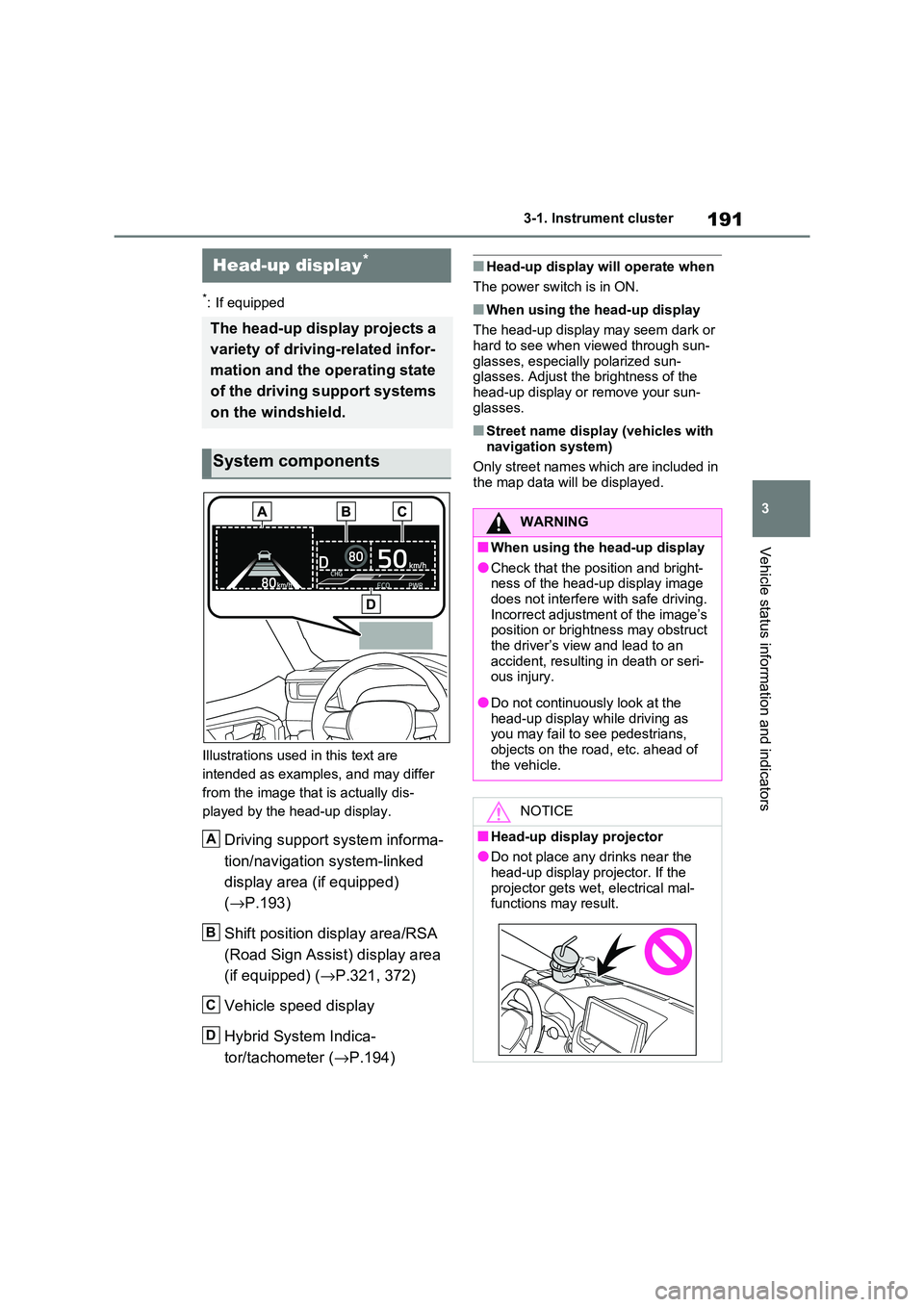
Illustrations used in this text are
intended as examples, and may differ
from the image that is actually dis -
played by the head-up display.
Driving support system informa -
tion/navigation system-linked
display area (if equipped)
( →P.193)
Shift position display area/RSA
(Road Sign Assist) display area
(if equipped) ( →P.321, 372)
Vehicle speed display
Hybrid System Indica -
tor/tachometer ( →P.194)
■Head-up display will operate when
The power switch is in ON.
■When using the head-up display
The head-up display may seem dark or
hard to see when v iewed through sun- glasses, especiall y polarized sun-
glasses. Adjust t he brightness of the
head-up display or remove your sun - glasses.
■Street name displ ay (vehicles with
navigation system)
Only street names which are included in the map data will be displayed.
Head-up display*
The head-up display projects a
variety of driving-related infor -
mation and the operating state
of the driving support systems
on the windshield.
System components
A
B
C
D
WARNING
■When using the head-up display
●Check that the position and bright -
ness of the head-up display image does not interfere with safe driving.
Incorrect adjustment of the image’s
position or bright ness may obstruct the driver’s view and lead to an
accident, resulti ng in death or seri-
ous injury.
●Do not continuously look at the
head-up display while driving as you may fail to see pedestrians,
objects on the roa d, etc. ahead of
the vehicle.
NOTICE
■Head-up display projector
●Do not place any drinks near the
head-up display projector. If the projector gets wet , electrical mal-
functions may result.
Page 195 of 666
193
3
3-1. Instrument cluster
Vehicle status information and indicators
• Driving support system information
display
• Compass (if equipped)
• Audio system operation status
Display angle
Select to adjust the angle of the head-
up display.
■Enabling/disabling of the head-up
display
If the head-up display is disabled, it will remain disabled when the power switch
is turned off then back to ON.
■Display brightness
The brightness of t he head-up display
can be adjusted on screen of the
multi-information display. Also, it is auto -
matically adjusted according to the
ambient brightness.
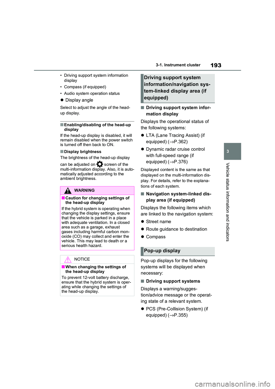
■Driving support system infor -
mation display
Displays the operational status of
the following systems:
LTA (Lane Tracing Assist) (if
equipped) ( →P.362)
Dynamic radar cruise control
with full-speed range (if
equipped) ( →P.376)
Displayed content is the same as that
displayed on the multi-information dis -
play. For details, refer to the explana -
tions of each system.
■Navigation system-linked dis -
play area (if equipped)
Displays the follo wing items which
are linked to the navigation system:
Street name
Route guidance to destination
Compass
Pop-up displays for the following
systems will be displayed when
necessary:
■Driving support systems
Displays a warning/sugges -
tion/advice messa ge or the operat-
ing state of a relevant system.
PCS (Pre-Collision System) (if
equipped) ( →P.355)
WARNING
■Caution for changing settings of the head-up display
If the hybrid system i s operating when
changing the display settings, ensure that the vehicle is parked in a place
with adequate ventilat ion. In a closed
area such as a garage, exhaust gases including harmful carbon mon -
oxide (CO) may collect and enter the
vehicle. This may lead to death or a serious health hazard.
NOTICE
■When changing the settings of
the head-up display
To prevent 12-volt battery discharge,
ensure that the hyb rid system is oper-
ating while changing the settings of the head-up display.
Driving support system
information/navigation sys -
tem-linked display area (if
equipped)
Pop-up display
Page 197 of 666
195
3
3-1. Instrument cluster
Vehicle status information and indicators
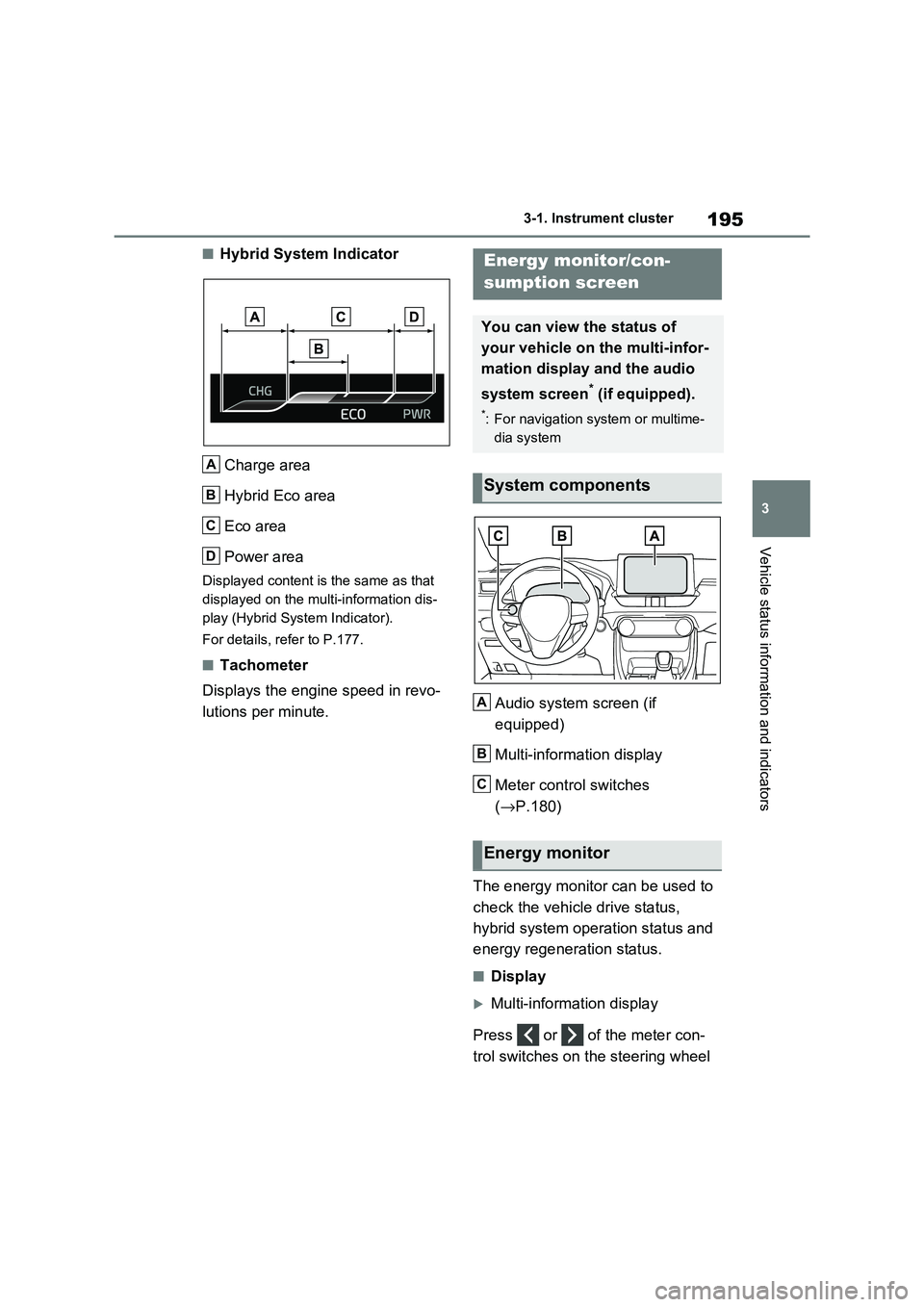
■Hybrid System Indicator
Charge area
Hybrid Eco area
Eco area
Power area
Displayed content is the same as that
displayed on the multi-information dis -
play (Hybrid System Indicator).
For details, refer to P.177.
■Tachometer
Displays the engine speed in revo -
lutions per minute. Audio system screen (if
equipped)
Multi-information display
Meter control switches
( →P.180)
The energy monitor can be used to
check the vehicl e drive status,
hybrid system operation status and
energy regeneration status.
■Display
Multi-information display
Press or of the meter con -
trol switches on the steering wheel
A
B
C
D
Energy monitor/con-
sumption screen
You can view the status of
your vehicle on the multi-infor-
mation display and the audio
system screen* (if equipped).
*: For navigation system or multime -
dia system
System components
Energy monitor
A
B
C
Page 198 of 666
1963-1. Instrument cluster
and select , and then press
or to select the energy mon -
itor display.
Audio system screen (without
navigation function)
1 Press the “MENU” button.
2 Select “Info” on the “Menu”
screen.
If a screen other than “Energy monitor”
is displayed, select “Energy”.
Audio system screen (with navi -
gation function)
1 Press the “MENU” button.
2 Select “Info” on the “Menu”
screen.
3 Select “ECO” on the “Informa-
tion” screen.
If a screen other than “Energy monitor”
is displayed, select “Energy”.
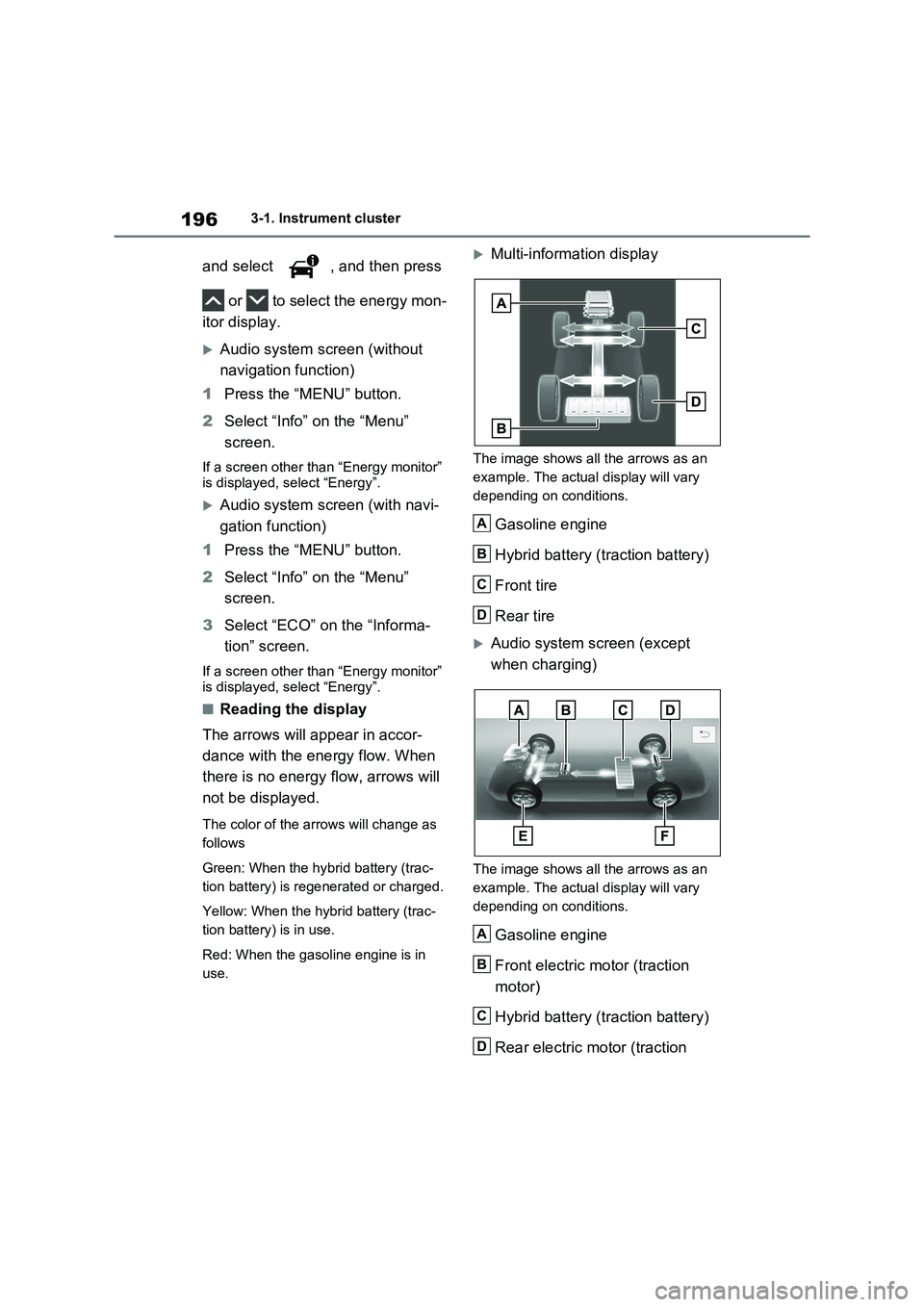
■Reading the display
The arrows will appear in accor-
dance with the energy flow. When
there is no energy flow, arrows will
not be displayed.
The color of the arrows will change as
follows
Green: When the hybr id battery (trac-
tion battery) is rege nerated or charged.
Yellow: When the hybrid battery (trac -
tion battery) is in use.
Red: When the gaso line engine is in
use.
Multi-information display
The image shows all the arrows as an
example. The actual display will vary
depending on conditions.
Gasoline engine
Hybrid battery (traction battery)
Front tire
Rear tire
Audio system screen (except
when charging)
The image shows all the arrows as an
example. The actual display will vary
depending on conditions.
Gasoline engine
Front electric motor (traction
motor)
Hybrid battery (traction battery)
Rear electric motor (traction
A
B
C
D
A
B
C
D
Page 200 of 666
1983-1. Instrument cluster
warming up is finished.
Hybrid system output may be restricted when the gasoline engine is displayed in
blue.
■Display
Audio system without navigation
function
1 Press the “MENU” button.
2 Select “Info” on the “Menu”
screen.
3 Select “Trip information” or “His-
tory”.
Audio system with navigation
function
1 Press the “MENU” button.
2 Select “Info” on the “Menu”
screen.
3 Select “ECO” on the “Informa-
tion” screen.
4 Select “Trip information” or “His-
tory”.
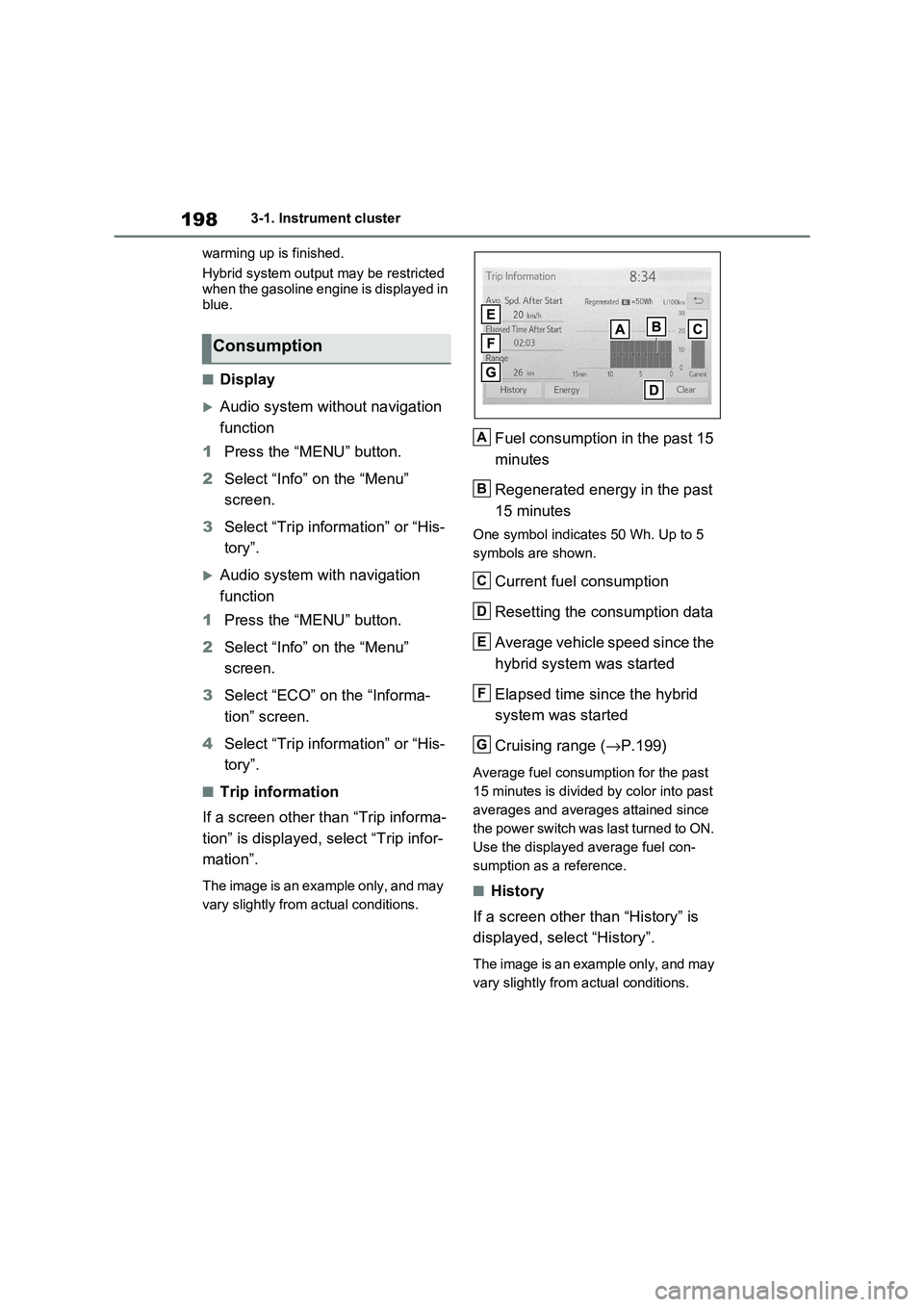
■Trip information
If a screen other than “Trip informa -
tion” is displayed, select “Trip infor -
mation”.
The image is an example only, and may
vary slightly from actual conditions.
Fuel consumption in the past 15
minutes
Regenerated energy in the past
15 minutes
One symbol indicate s 50 Wh. Up to 5
symbols are shown.
Current fuel consumption
Resetting the consumption data
Average vehicle speed since the
hybrid system was started
Elapsed time since the hybrid
system was started
Cruising range ( →P.199)
Average fuel consumption for the past
15 minutes is divided by color into past
averages and averages attained since
the power switch was last turned to ON.
Use the displayed average fuel con -
sumption as a reference.
■History
If a screen other than “History” is
displayed, select “History”.
The image is an example only, and may
vary slightly from actual conditions.
Consumption
A
B
C
D
E
F
G
Page 375 of 666
373
5
5-5. Using the driving support systems
Driving
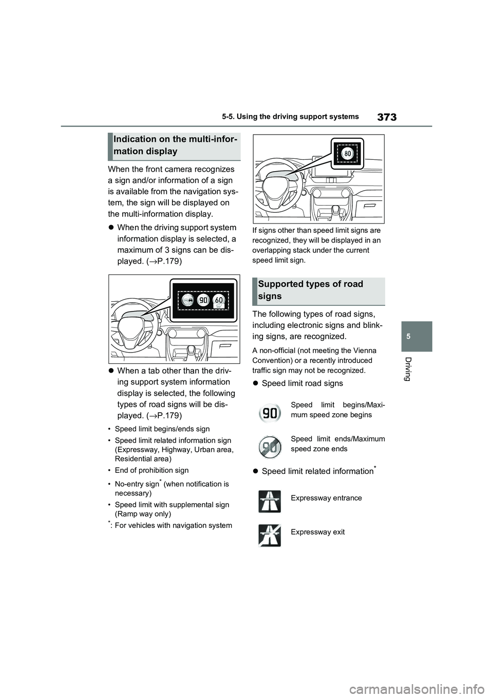
When the front camera recognizes
a sign and/or information of a sign
is available from the navigation sys -
tem, the sign will be displayed on
the multi-inform ation display.
When the driving support system
information display is selected, a
maximum of 3 signs can be dis -
played. ( →P.179)
When a tab other than the driv-
ing support system information
display is selected, the following
types of road signs will be dis -
played. ( →P.179)
• Speed limit begins/ends sign
• Speed limit related information sign
(Expressway, Highway, Urban area,
Residential area)
• End of prohibition sign
• No-entry sign* (when notification is
necessary)
• Speed limit with supplemental sign
(Ramp way only)
*: For vehicles with navigation system
If signs other than speed limit signs are
recognized, they will be displayed in an
overlapping stack under the current
speed limit sign.
The following types of road signs,
including electronic signs and blink -
ing signs, are recognized.
A non-official (not m eeting the Vienna
Convention) or a recently introduced
traffic sign may not be recognized.
Speed limit road signs
Speed limit related information*
Indication on the multi-infor-
mation display
Supported types of road
signs
Speed limit begins/Maxi -
mum speed zone begins
Speed limit ends/Maximum
speed zone ends
Expressway entrance
Expressway exit
Page 376 of 666
3745-5. Using the driving support systems
*: Displayed when a sign is recognized
but speed limit information for the
road is not available from the naviga -
tion system
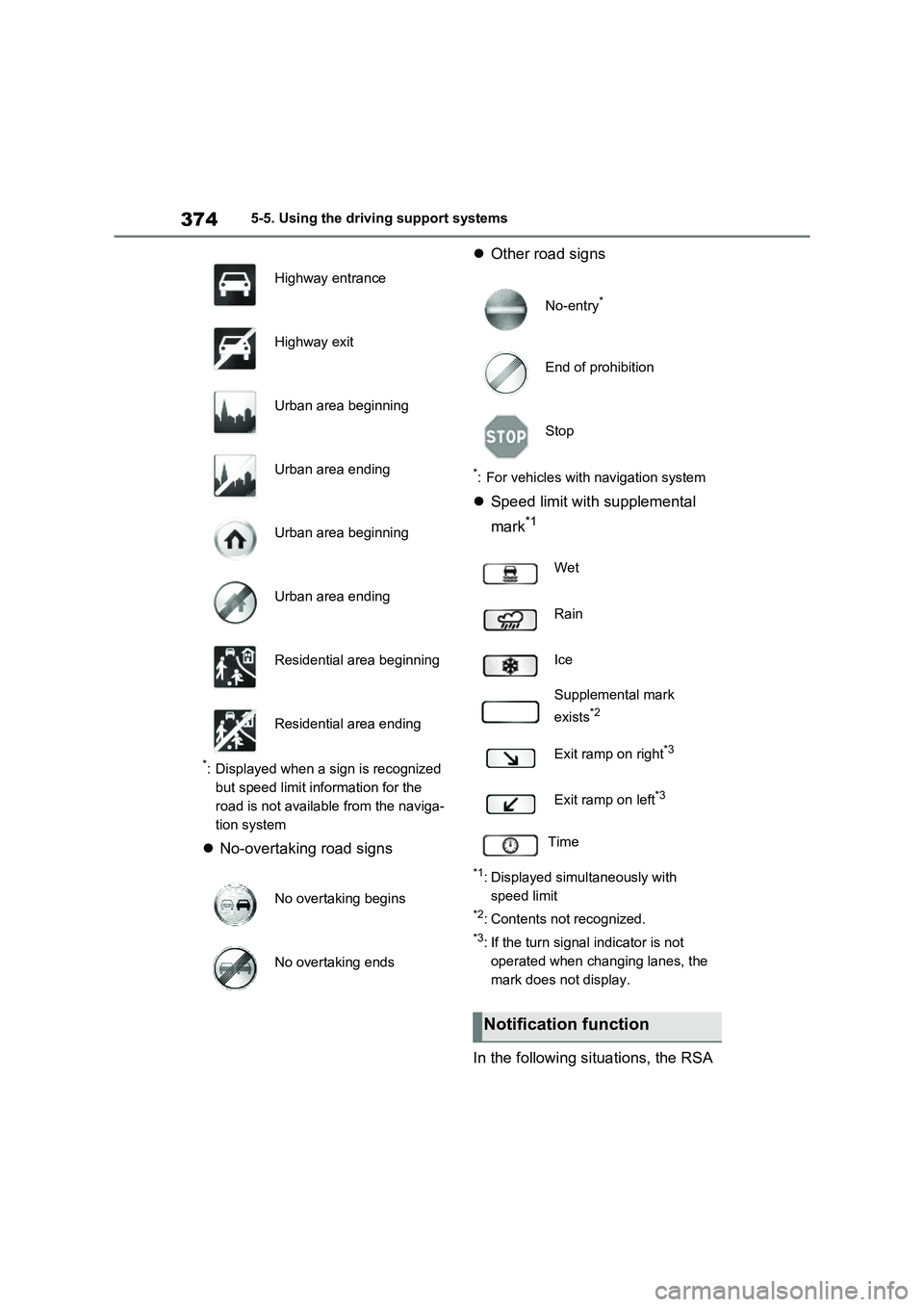
No-overtaking road signs
Other road signs
*: For vehicles with navigation system
Speed limit with supplemental
mark*1
*1: Displayed simultaneously with
speed limit
*2: Contents not recognized.
*3: If the turn signal indicator is not
operated when changing lanes, the
mark does not display.
In the following si tuations, the RSA
Highway entrance
Highway exit
Urban area beginning
Urban area ending
Urban area beginning
Urban area ending
Residential area beginning
Residential area ending
No overtaking begins
No overtaking ends
No-entry*
End of prohibition
Stop
Wet
Rain
Ice
Supplemental mark
exists*2
Exit ramp on right*3
Exit ramp on left*3
Time
Notification function