ESP TOYOTA RAV4 PLUG-IN HYBRID 2023 Owner's Guide
[x] Cancel search | Manufacturer: TOYOTA, Model Year: 2023, Model line: RAV4 PLUG-IN HYBRID, Model: TOYOTA RAV4 PLUG-IN HYBRID 2023Pages: 718, PDF Size: 167.55 MB
Page 374 of 718
3725-5. Using the driving support systems
When a vehicle is detected running ahead of you, the system automatically deceler-
ates your vehicle. When a greater reduction in vehicle speed is necessary, the sys-
tem applies the brakes (the stop lights will come on at this time). The system will
respond to changes in the speed of the vehicle ahead in order to maintain the vehi-
cle-to-vehicle distance set by the driver. Approach warning warns you when the sys-
tem cannot decelerate sufficiently to prevent your vehicle from closing in on the
vehicle ahead.
When the vehicle ahead of you stops, your vehicle will also stop (vehicle is stopped
by system control). After the vehicle ahead starts off, pressing the “+RES” switch or
depressing the accelerator pedal (start-off operation) will resume follow-up cruising.
If the start-off operation is not performed, system control continues to keep your
vehicle stopped.
When the turn signal lever is operated and your vehicle moves to an overtaking lane
while driving at 80 km/h (50 mph) or more, the vehicle will accelerate to help to over-
take a passing vehicle.
The system’s identification of what is an overtaking lane may be determined solely
based on the location of the steering wheel in the vehicle (left side driver position
versus right side driver position.) If the vehicle is driven to a region where the over-
taking lane is on a different side from where the vehicle is normally driven, the vehi-
cle may accelerate when the turn signal lever is operated in the opposite direction to
the overtaking lane (e.g., if the driver normally operates the vehicle in a region
where the overtaking lane is to the right but then drives to a region where the over-
taking lane is to the left, the vehicle may accelerate when the right turn signal is acti-
vated).
Example of acceleration
When there are no longer any preceding vehicles driving slower than the
set speed
The system accelerates until the set speed is reached. The system then returns to
constant speed cruising.
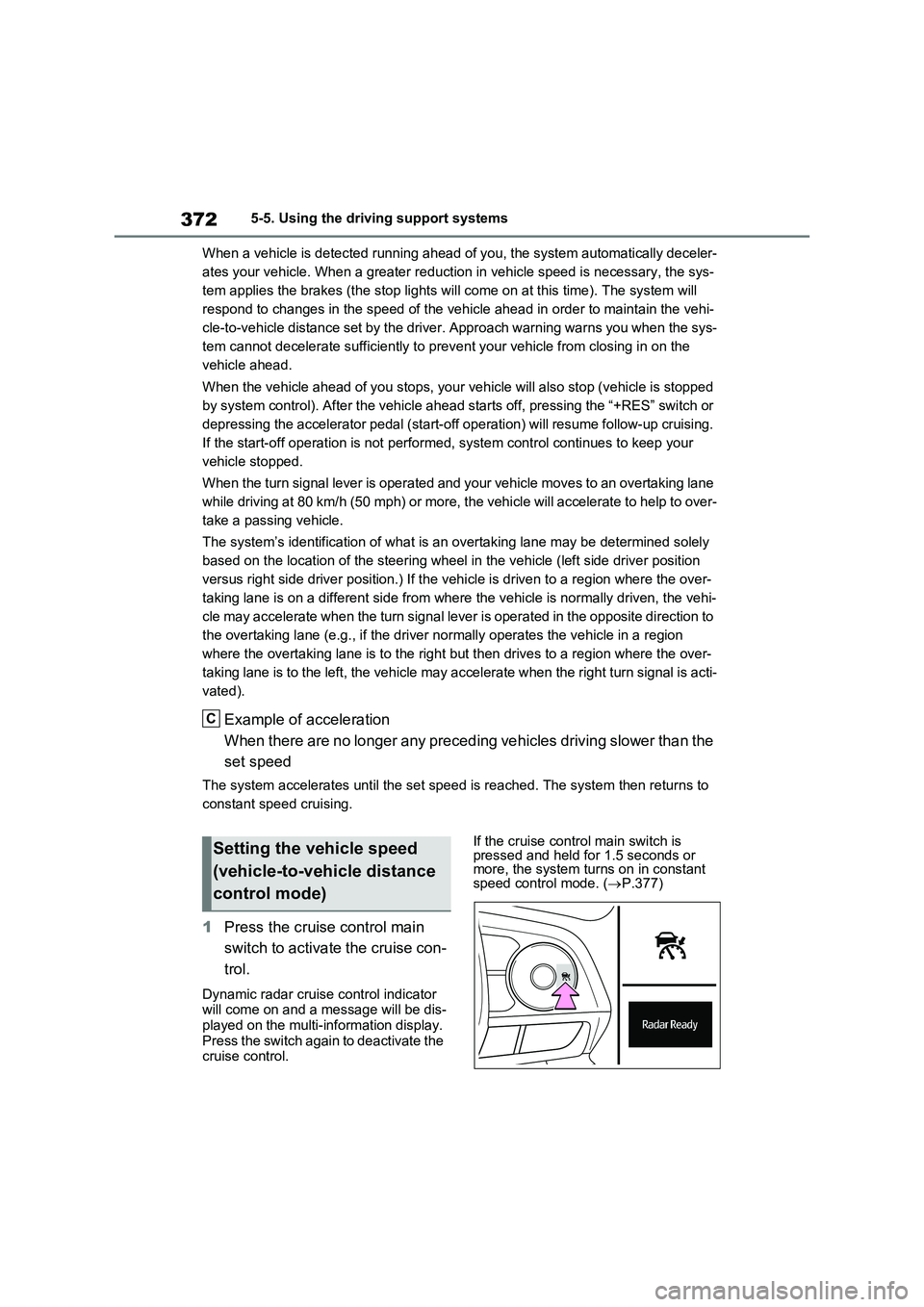
1Press the cruise control main
switch to activate the cruise con-
trol.
Dynamic radar cruise control indicator
will come on and a message will be dis-
played on the multi-information display.
Press the switch again to deactivate the
cruise control.If the cruise control main switch is
pressed and held for 1.5 seconds or
more, the system turns on in constant
speed control mode. (P.377)
C
Setting the vehicle speed
(vehicle-to-vehicle distance
control mode)
Page 376 of 718
3745-5. Using the driving support systems
*1: When the set speed is shown in
“km/h”
*2: When the set speed is shown in
“MPH”
Increasing the set speed by the
accelerator pedal
1 Accelerate with accelerator
pedal operation to the desired
vehicle speed
2 Press the “-SET” switch
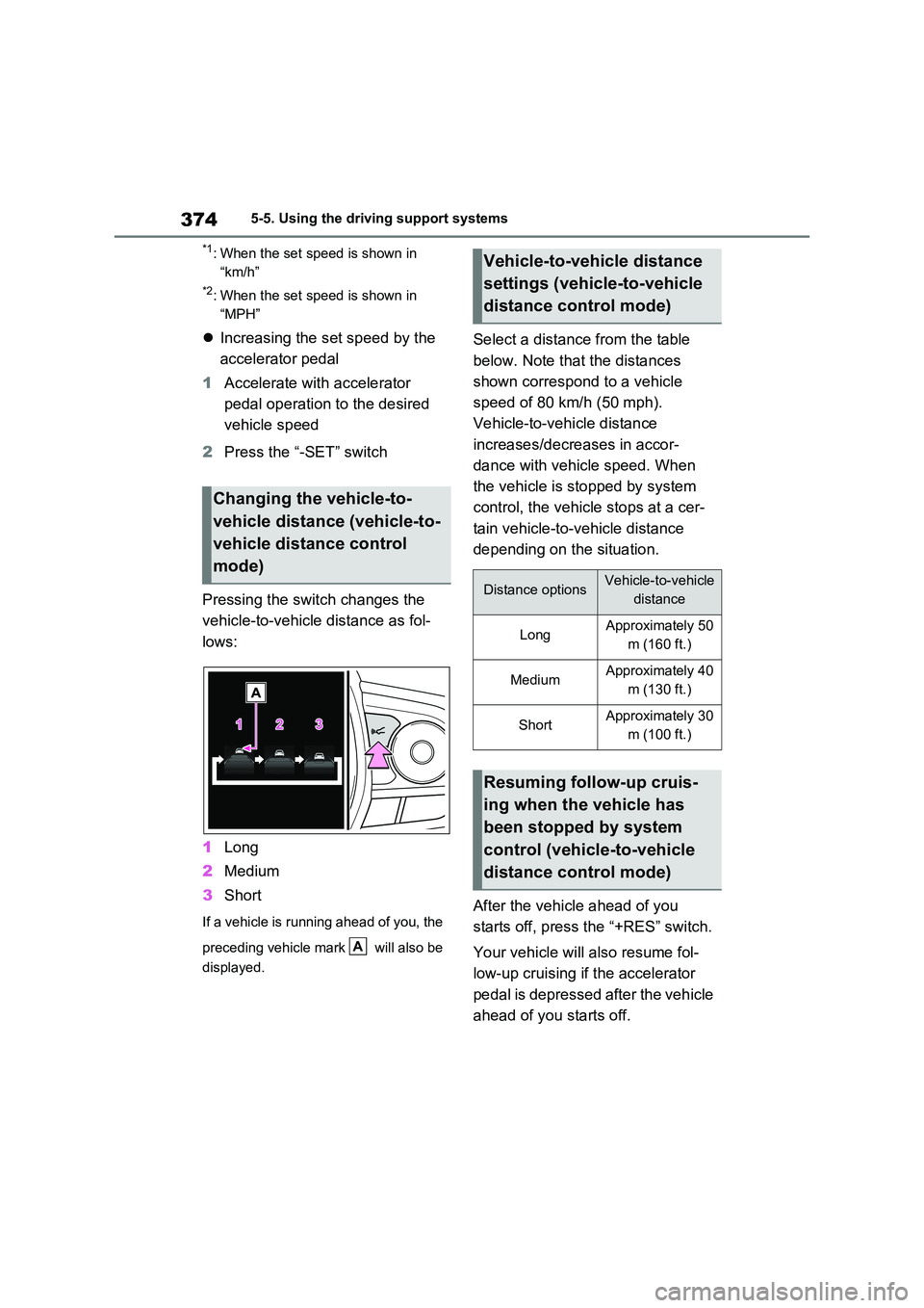
Pressing the switch changes the
vehicle-to-vehicle distance as fol-
lows:
1 Long
2 Medium
3 Short
If a vehicle is running ahead of you, the
preceding vehicle mark will also be
displayed.
Select a distance from the table
below. Note that the distances
shown correspond to a vehicle
speed of 80 km/h (50 mph).
Vehicle-to-vehicle distance
increases/decreases in accor-
dance with vehicle speed. When
the vehicle is stopped by system
control, the vehicle stops at a cer-
tain vehicle-to-vehicle distance
depending on the situation.
After the vehicle ahead of you
starts off, press the “+RES” switch.
Your vehicle will also resume fol-
low-up cruising if the accelerator
pedal is depressed after the vehicle
ahead of you starts off.
Changing the vehicle-to-
vehicle distance (vehicle-to-
vehicle distance control
mode)
A
Vehicle-to-vehicle distance
settings (vehicle-to-vehicle
distance control mode)
Distance optionsVehicle-to-vehicle
distance
LongApproximately 50
m (160 ft.)
MediumApproximately 40
m (130 ft.)
ShortApproximately 30
m (100 ft.)
Resuming follow-up cruis-
ing when the vehicle has
been stopped by system
control (vehicle-to-vehicle
distance control mode)
Page 381 of 718
379
5 5-5. Using the driving support systems
Driving
• The driver’s door is opened.
• The vehicle has been stopped for
about 3 minutes
If vehicle-to-vehicle distance control
mode is automatically canceled for any
reasons other than the above, there
may be a malfunction in the system.
Contact any authorized Toyota retailer
or Toyota authorized repairer, or any
reliable repairer.
■Automatic cancelation of constant
speed control mode
Constant speed control mode is auto-
matically canceled in the following situa-
tions:
●Actual vehicle speed is more than
approximately 16 km/h (10 mph)
below the set vehicle speed.
●Actual vehicle speed falls below
approximately 30 km/h (20 mph).
●VSC is activated.
●TRC is activated for a period of time.
●When the VSC or TRC system is
turned off.
●When the brake control or output
restriction control of a driving support
system operates.
(For example: Pre-Collision System,
Drive-Start Control)
●The parking brake is operated.
If constant speed control mode is auto-
matically canceled for any reasons other
than the above, there may be a malfunc-
tion in the system. Contact any autho-
rized Toyota retailer or Toyota
authorized repairer, or any reliable
repairer.
■Situations in which the curve speed
reduction function may not operate
In situations such as the following, the
curve speed reduction function may not
operate:
●When the vehicle is being driven
around a gentle curve
●When the accelerator pedal is being
depressed
●When the vehicle is being driven
around an extremely short curve
■The Dynamic Radar Cruise Control
with Road Sign Assist may not
operate properly when (vehicles
with RSA)
As the Dynamic Radar Cruise Control
with Road Sign Assist may not operate
properly in conditions in which RSA may
not operate or detect correctly
(P.367), when using this function,
make sure to check the speed limit sign
displayed.
In the following situations, the set speed
may not be changed to the recognized
speed limit by pressing and holding the
“+RES”/“-SET” switch.
●If speed limit information is not avail-
able
●When the recognized speed limit is
the same as the set speed
●When the recognized speed limit is
outside of the speed range that the
dynamic radar cruise control system
can operate
■Brake operation
A brake operation sound may be heard
and the brake pedal response may
change, but these are not malfunctions.
■Warning messages and buzzers for
dynamic radar cruise control with
full-speed range
Warning messages and buzzers are
used to indicate a system malfunction or
to inform the driver of the need for cau-
tion while driving. If a warning message
is shown on the multi-information dis-
play, read the message and follow the
instructions. (P.341, 544)
■When the sensor may not be cor-
rectly detecting the vehicle ahead
In the case of the following and depend-
ing on the conditions, operate the brake
pedal when deceleration of the system
is insufficient or operate the accelerator
pedal when acceleration is required.
Page 388 of 718
3865-5. Using the driving support systems
■Automatic speed limiter cancella-
tion
The set speed is automatically canceled when the cruise control is activated.
■If the speed limiter indicator turns
off and “Speed Limiter Malfunction Visit Your Dealer” is displayed
Stop the hybrid system and then restart
the hybrid system. After restarting the hybrid system, set the speed limiter.If the speed limiter cannot be set, there
may be a malfunction in the speed lim- iter system. Have the vehicle inspected by any authorized Toyota retailer or
Toyota authorized repairer, or any reli- able repairer.
*: If equipped
BSM (Blind Spot Moni-
tor)*
The Blind Spot Monitor is a
system that has 2 functions:
The BSM (Blind Spot Monitor)
function
Assists the driver in making a
decision when changing lanes
The RCTA (Rear Crossing
Traffic Alert) function
Assists the driver when backing
up
These functions use the same
sensors.
WARNING
■Cautions regarding the use of the BSM function
The driver is solely responsible for safe driving. Always drive safely, tak-ing care to observe your surround-
ings. The BSM function is a supplementary function which alerts the driver that a
vehicle is in a blind spot of the outside rear view mirrors or is approaching rapidly from behind into a blind spot.
Do not overly rely on the BSM func- tion. As the function cannot judge if it is safe to change lanes, over reliance
could lead to an accident resulting in death or serious injury.
As the system may not function cor-
rectly under certain conditions, the driver’s own visual confirmation of safety is necessary.
Page 389 of 718
387
5
5-5. Using the driving support systems
Driving
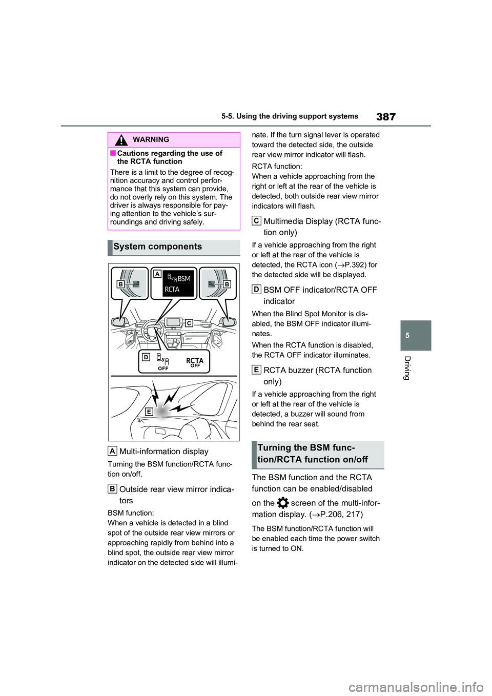
Multi-information display
Turning the BSM function/RCTA func-
tion on/off.
Outside rear view mirror indica-
tors
BSM function:
When a vehicle is detected in a blind
spot of the outside rear view mirrors or
approaching rapidly from behind into a
blind spot, the outside rear view mirror
indicator on the detected side will illumi-
nate. If the turn signal lever is operated
toward the detected side, the outside
rear view mirror indicator will flash.
RCTA function:
When a vehicle approaching from the
right or left at the rear of the vehicle is
detected, both outside rear view mirror
indicators will flash.
Multimedia Display (RCTA func-
tion only)
If a vehicle approaching from the right
or left at the rear of the vehicle is
detected, the RCTA icon ( P.392) for
the detected side will be displayed.
BSM OFF indicator/RCTA OFF
indicator
When the Blind Spot Monitor is dis-
abled, the BSM OFF indicator illumi-
nates.
When the RCTA function is disabled,
the RCTA OFF indicator illuminates.
RCTA buzzer (RCTA function
only)
If a vehicle approaching from the right
or left at the rear of the vehicle is
detected, a buzzer will sound from
behind the rear seat.
The BSM function and the RCTA
function can be enabled/disabled
on the screen of the multi-infor-
mation display. ( P.206, 217)
The BSM function/RCTA function will
be enabled each time the power switch
is turned to ON.
WARNING
■Cautions regarding the use of the RCTA function
There is a limit to the degree of recog- nition accuracy and control perfor-mance that this system can provide,
do not overly rely on this system. The driver is always responsible for pay-ing attention to the vehicle’s sur-
roundings and driving safely.
System components
A
B
Turning the BSM func-
tion/RCTA function on/off
C
D
E
Page 390 of 718
3885-5. Using the driving support systems
■Outside rear view mirror indicators visibility
In strong sunlight, the outside rear view mirror indicator may be difficult to see.
■Hearing the RCTA buzzer
The RCTA buzzer may be difficult to
hear over loud noises such as high audio volume.
■When “Blind Spot Monitor Unavail-able” or “RCTA Unavailable” is
shown on the multi-information display
The sensor voltage has become abnor-
mal, or water, snow, mud, etc., may be built up in the vicinity of the sensor area of the rear bumper. ( P.388)
Removing the water, snow, mud, etc., from the vicinity of the sensor area should return it to normal.
Also, the sensor may not function nor- mally when used in extremely hot or cold weather.
■When “Blind Spot Monitor Malfunc-
tion Visit Your Dealer” or “RCTA Malfunction Visit Your Dealer” is shown on the multi-information
display
There may be a sensor malfunction or misaligned. Have the vehicle inspected
at any authorized Toyota retailer or Toyota authorized repairer, or any reli-
able repairer.
■Customization
Some functions can be customized. ( P.206, 217)
WARNING
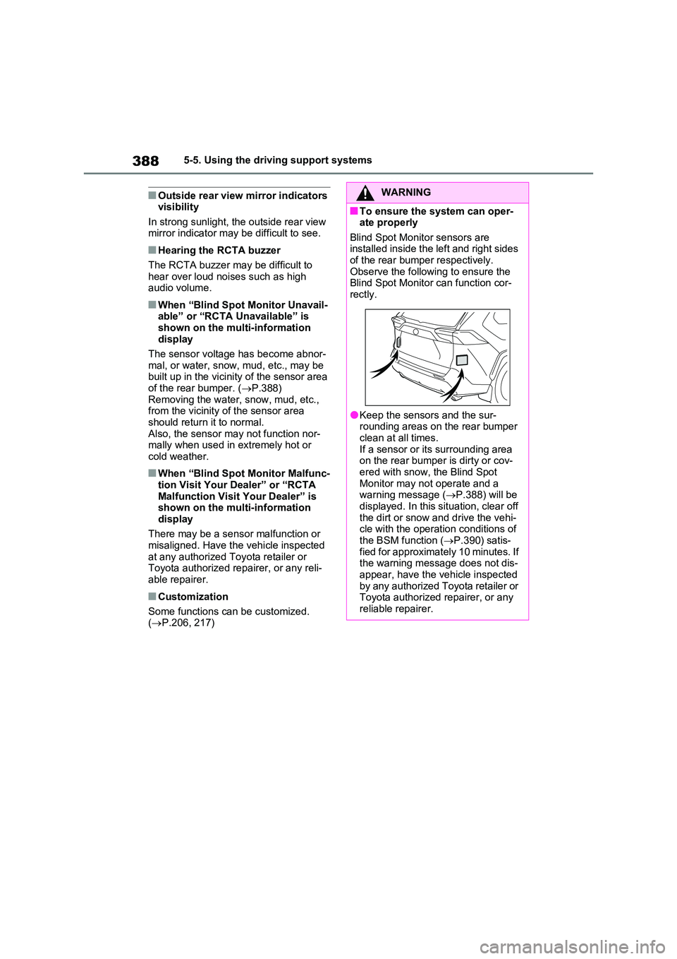
■To ensure the system can oper- ate properly
Blind Spot Monitor sensors are installed inside the left and right sides of the rear bumper respectively.
Observe the following to ensure the Blind Spot Monitor can function cor-rectly.
●Keep the sensors and the sur-rounding areas on the rear bumper
clean at all times. If a sensor or its surrounding area on the rear bumper is dirty or cov-
ered with snow, the Blind Spot Monitor may not operate and a warning message ( P.388) will be
displayed. In this situation, clear off the dirt or snow and drive the vehi-cle with the operation conditions of
the BSM function ( P.390) satis- fied for approximately 10 minutes. If the warning message does not dis-
appear, have the vehicle inspected by any authorized Toyota retailer or Toyota authorized repairer, or any
reliable repairer.
Page 394 of 718
3925-5. Using the driving support systems
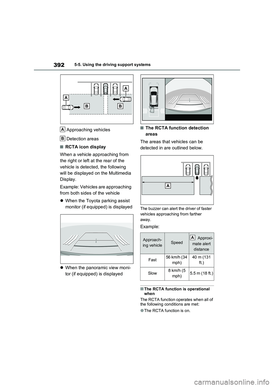
Approaching vehicles
Detection areas
■RCTA icon display
When a vehicle approaching from
the right or left at the rear of the
vehicle is detected, the following
will be displayed on the Multimedia
Display.
Example: Vehicles are approaching
from both sides of the vehicle
When the Toyota parking assist
monitor (if equipped) is displayed
When the panoramic view moni-
tor (if equipped) is displayed
■The RCTA function detection
areas
The areas that vehicles can be
detected in are outlined below.
The buzzer can alert the driver of faster
vehicles approaching from farther
away.
Example:
■The RCTA function is operational
when
The RCTA function operates when all of
the following conditions are met:
●The RCTA function is on.
A
B
Approach-
ing vehicleSpeed Approxi-
mate alert
distance
Fast56 km/h (34
mph)40 m (131
ft.)
Slow8 km/h (5
mph)5.5 m (18 ft.)
A
Page 399 of 718
397
5
5-5. Using the driving support systems
Driving
To re-enable the system, select on
the multi-information display, select
and turn it on.
If the system is disabled, it will remain
off even if the power switch is turned to
ON after the power switch has been
turned off.
■The system can be operated when
●The power switch is in ON.
●Toyota parking assist-sensor function is on.
●The vehicle speed is less than about 10 km/h (6 mph).
●The shift lever is in other than P.
■If “Clean Parking Assist Sensor” is displayed on the multi-information
display
A sensor may be covered with ice, snow, dirt, etc. Remove the ice, snow,
dirt, etc., from the sensor to return the system to normal.
Also, due to ice forming on a sensor at
low temperatures, a warning message
WARNING
■Cautions regarding the use of the system
There is a limit to the degree of recog- nition accuracy and control perfor-mance that this system can provide,
do not overly rely on this system. The driver is always responsible for pay-ing attention to the vehicle’s sur-
roundings and driving safely.
■To ensure the system can oper-
ate properly
Observe the following precautions. Failing to do so may result in the vehi-
cle being unable to be driven safely and possibly cause an accident.
●Do not damage the sensors, and always keep them clean.
●Do not attach a sticker or install an electronic component, such as a backlit license plate (especially fluo-
rescent type), fog lights, fender pole or wireless antenna near a radar sensor.
●Do not subject the surrounding area of the sensor to a strong impact. If
subjected to an impact, have the vehicle inspected by any authorized Toyota retailer or Toyota authorized
repairer, or any reliable repairer. If the front or rear bumper needs to be removed/installed or replaced,
contact any authorized Toyota retailer or Toyota authorized repairer, or any reliable repairer.
●Do not modify, disassemble or paint the sensors.
●Do not attach a license plate cover.
●Keep your tires properly inflated.
■When to disable the function
In the following situations, disable the
function as it may operate even though there is no possibility of a colli-sion.
●Failing to observe the warnings above.
●A non-genuine Toyota suspension (lowered suspension, etc.) is installed.
■Notes when washing the vehicle
Do not apply intensive bursts of water
or steam to the sensor area.
Doing so may result in the sensor malfunctioning.
●When using a high pressure washer to wash the vehicle, do not
spray the sensors directly, as doing so may cause a sensor to malfunc-tion.
●When using steam to clean the vehicle, do not direct steam too
close to the sensors as doing so may cause a sensor to malfunction.
Page 400 of 718
3985-5. Using the driving support systems
may be displayed or the sensor may not
be able to detect an object. Once the ice
melts, the system will return to normal.
If a warning message is displayed even
if the sensor is clean, there may be a
sensor malfunction. Have the vehicle
inspected by any authorized Toyota
retailer or Toyota authorized repairer, or
any reliable repairer.
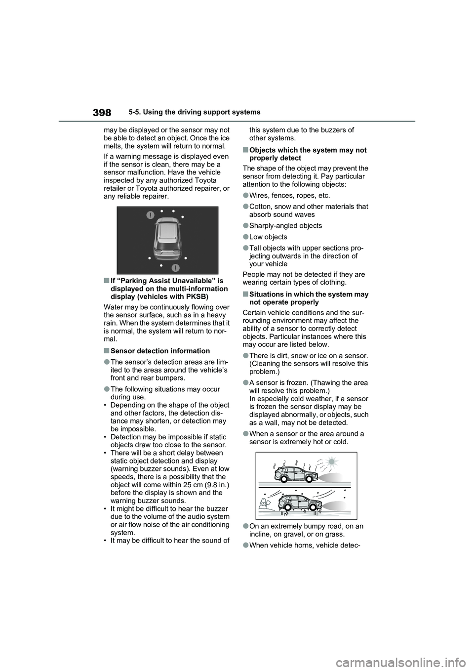
■If “Parking Assist Unavailable” is
displayed on the multi-information
display (vehicles with PKSB)
Water may be continuously flowing over
the sensor surface, such as in a heavy
rain. When the system determines that it
is normal, the system will return to nor-
mal.
■Sensor detection information
●The sensor’s detection areas are lim-
ited to the areas around the vehicle’s
front and rear bumpers.
●The following situations may occur
during use.
• Depending on the shape of the object
and other factors, the detection dis-
tance may shorten, or detection may
be impossible.
• Detection may be impossible if static
objects draw too close to the sensor.
• There will be a short delay between
static object detection and display
(warning buzzer sounds). Even at low
speeds, there is a possibility that the
object will come within 25 cm (9.8 in.)
before the display is shown and the
warning buzzer sounds.
• It might be difficult to hear the buzzer
due to the volume of the audio system
or air flow noise of the air conditioning
system.
• It may be difficult to hear the sound of this system due to the buzzers of
other systems.
■Objects which the system may not
properly detect
The shape of the object may prevent the
sensor from detecting it. Pay particular
attention to the following objects:
●Wires, fences, ropes, etc.
●Cotton, snow and other materials that
absorb sound waves
●Sharply-angled objects
●Low objects
●Tall objects with upper sections pro-
jecting outwards in the direction of
your vehicle
People may not be detected if they are
wearing certain types of clothing.
■Situations in which the system may
not operate properly
Certain vehicle conditions and the sur-
rounding environment may affect the
ability of a sensor to correctly detect
objects. Particular instances where this
may occur are listed below.
●There is dirt, snow or ice on a sensor.
(Cleaning the sensors will resolve this
problem.)
●A sensor is frozen. (Thawing the area
will resolve this problem.)
In especially cold weather, if a sensor
is frozen the sensor display may be
displayed abnormally, or objects, such
as a wall, may not be detected.
●When a sensor or the area around a
sensor is extremely hot or cold.
●On an extremely bumpy road, on an
incline, on gravel, or on grass.
●When vehicle horns, vehicle detec-
Page 405 of 718
403
5
5-5. Using the driving support systems
Driving
*: If equipped
■Parking Support Brake func-
tion (static objects)
P.407
■Parking Support Brake func-
tion (rear-crossing vehicles)
P.410
PKSB (Parking Support
Brake)*
The Parking Support Brake
system consists of the follow-
ing functions that operate
when driving at a low speed or
backing up, such as when
parking. When the system
determines that the possibility
of a collision with a detected
object is high, a warning oper-
ates to urge the driver to take
evasive action. If the system
determines that the possibility
of a collision with a detected
object is extremely high, the
brakes are automatically
applied to help avoid the colli-
sion or help reduce the impact
of the collision.
PKSB (Parking Support
Brake) system
WARNING
■Cautions regarding the use of the system
Do not overly rely on the system, as doing so may lead to an accident.
Always drive while checking the
safety of the surroundings of the vehi- cle.
Depending on the vehicle and road
conditions, weather, etc., the system may not operate.
The detection capabilities of sensors
and radars are limited. Always drive while checking the safety of the sur-roundings of the vehicle.
●The driver is solely responsible for safe driving. Always drive carefully,
taking care to observe your sur- roundings. The Parking Support Brake system is designed to pro-
vide support to lessen the severity of collisions. However, it may not operate in some situations.
●The Parking Support Brake system is not designed to stop the vehicle
completely. Additionally, even if the system has stopped the vehicle, it is necessary to depress the brake
pedal immediately as brake control will be canceled after approximately 2 seconds.
●It is extremely dangerous to check the system operations by intention-
ally driving the vehicle into the direction of a wall, etc. Never attempt such actions.
■When to disable the Parking Sup-port Brake
In the following situations, disable the Parking Support Brake as the system may operate even though there is no
possibility of a collision.
●When inspecting the vehicle using
a chassis roller, chassis dynamo or free roller.