TOYOTA SIENNA 2007 Service Repair Manual
SIENNA 2007
TOYOTA
TOYOTA
https://www.carmanualsonline.info/img/14/57466/w960_57466-0.png
TOYOTA SIENNA 2007 Service Repair Manual
Trending: wheel size, compression ratio, voltage regulator, Rear brake, catalytic converter, fuel cap, tire size
Page 2421 of 3000
BC–60BRAKE CONTROL – ANTI-LOCK BRAKE SYSTEM
BC
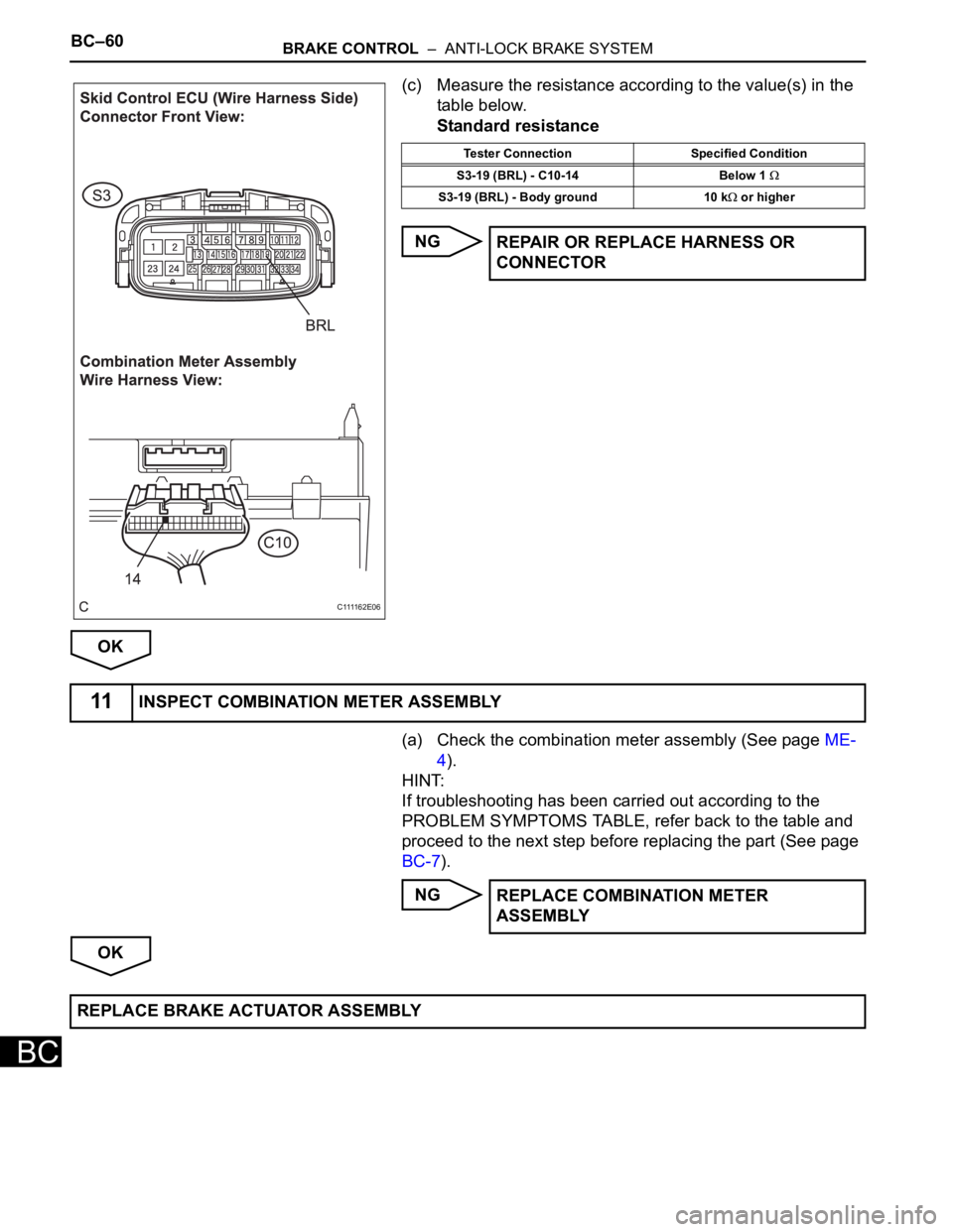
(c) Measure the resistance according to the value(s) in the
table below.
Standard resistance
NG
OK
(a) Check the combination meter assembly (See page ME-
4).
HINT:
If troubleshooting has been carried out according to the
PROBLEM SYMPTOMS TABLE, refer back to the table and
proceed to the next step before replacing the part (See page
BC-7).
NG
OK
C 1111 6 2 E 0 6
Tester Connection Specified Condition
S3-19 (BRL) - C10-14 Below 1
S3-19 (BRL) - Body ground 10 k or higher
REPAIR OR REPLACE HARNESS OR
CONNECTOR
11INSPECT COMBINATION METER ASSEMBLY
REPLACE COMBINATION METER
ASSEMBLY
REPLACE BRAKE ACTUATOR ASSEMBLY
Page 2422 of 3000
BRAKE CONTROL – ANTI-LOCK BRAKE SYSTEMBC–61
BC
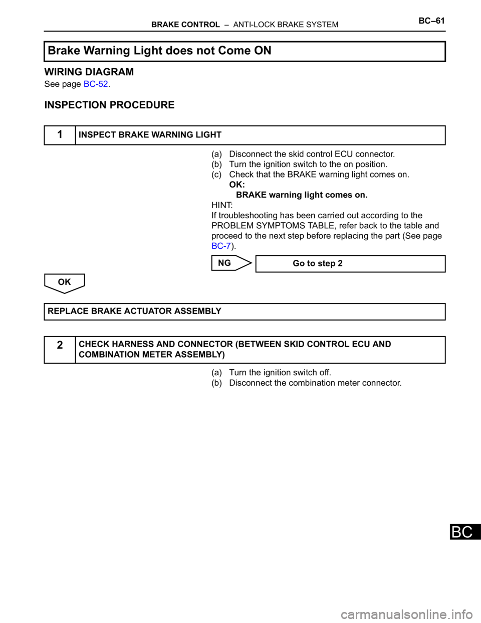
WIRING DIAGRAM
See page BC-52.
INSPECTION PROCEDURE
(a) Disconnect the skid control ECU connector.
(b) Turn the ignition switch to the on position.
(c) Check that the BRAKE warning light comes on.
OK:
BRAKE warning light comes on.
HINT:
If troubleshooting has been carried out according to the
PROBLEM SYMPTOMS TABLE, refer back to the table and
proceed to the next step before replacing the part (See page
BC-7).
NG
OK
(a) Turn the ignition switch off.
(b) Disconnect the combination meter connector.
Brake Warning Light does not Come ON
1INSPECT BRAKE WARNING LIGHT
Go to step 2
REPLACE BRAKE ACTUATOR ASSEMBLY
2CHECK HARNESS AND CONNECTOR (BETWEEN SKID CONTROL ECU AND
COMBINATION METER ASSEMBLY)
Page 2423 of 3000
BC–62BRAKE CONTROL – ANTI-LOCK BRAKE SYSTEM
BC
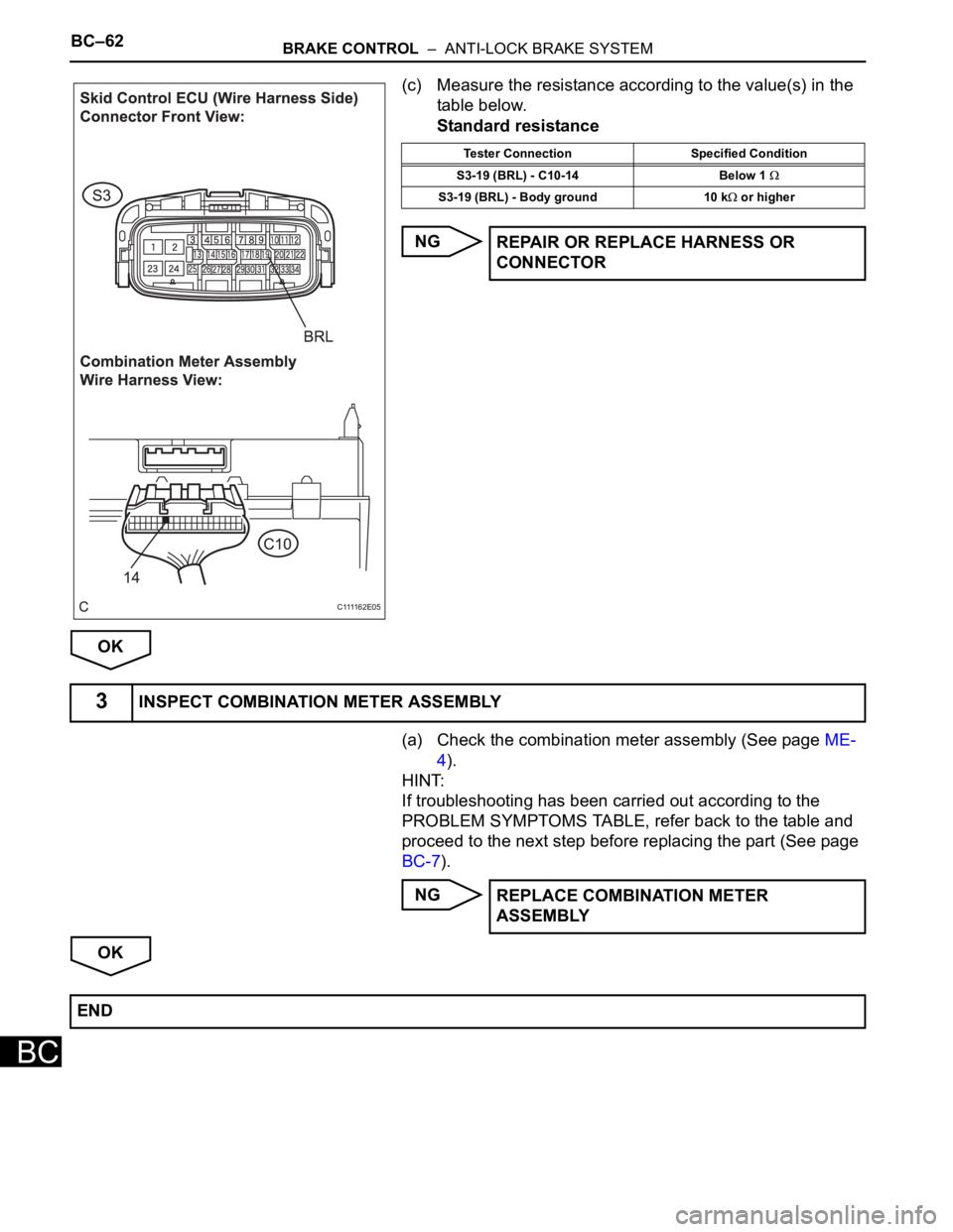
(c) Measure the resistance according to the value(s) in the
table below.
Standard resistance
NG
OK
(a) Check the combination meter assembly (See page ME-
4).
HINT:
If troubleshooting has been carried out according to the
PROBLEM SYMPTOMS TABLE, refer back to the table and
proceed to the next step before replacing the part (See page
BC-7).
NG
OK
C 1111 6 2 E 0 5
Tester Connection Specified Condition
S3-19 (BRL) - C10-14 Below 1
S3-19 (BRL) - Body ground 10 k or higher
REPAIR OR REPLACE HARNESS OR
CONNECTOR
3INSPECT COMBINATION METER ASSEMBLY
REPLACE COMBINATION METER
ASSEMBLY
END
Page 2424 of 3000
BRAKE CONTROL – ANTI-LOCK BRAKE SYSTEMBC–63
BC
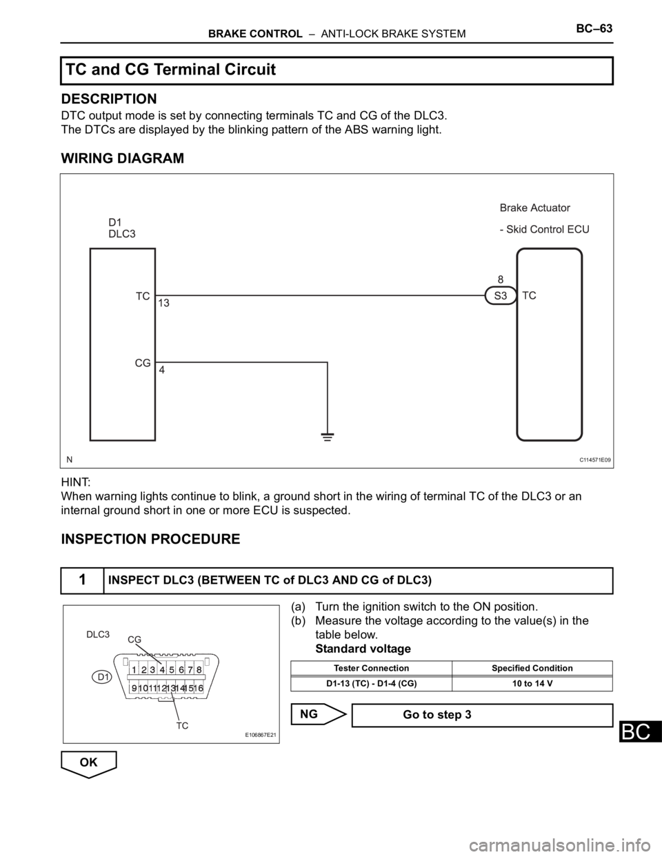
DESCRIPTION
DTC output mode is set by connecting terminals TC and CG of the DLC3.
The DTCs are displayed by the blinking pattern of the ABS warning light.
WIRING DIAGRAM
HINT:
When warning lights continue to blink, a ground short in the wiring of terminal TC of the DLC3 or an
internal ground short in one or more ECU is suspected.
INSPECTION PROCEDURE
(a) Turn the ignition switch to the ON position.
(b) Measure the voltage according to the value(s) in the
table below.
Standard voltage
NG
OK
TC and CG Terminal Circuit
1INSPECT DLC3 (BETWEEN TC of DLC3 AND CG of DLC3)
C114571E09
E106867E21
Tester Connection Specified Condition
D1-13 (TC) - D1-4 (CG) 10 to 14 V
Go to step 3
Page 2425 of 3000
BC–64BRAKE CONTROL – ANTI-LOCK BRAKE SYSTEM
BC
(a) Turn the ignition switch off.
(b) Disconnect the skid control ECU connector.
(c) Measure the resistance according to the value(s) in the
table below.
Standard resistance
NG
OK
(a) Turn the ignition switch off.
(b) Measure the resistance according to the value(s) in the
table below.
Standard resistance
NG
OK
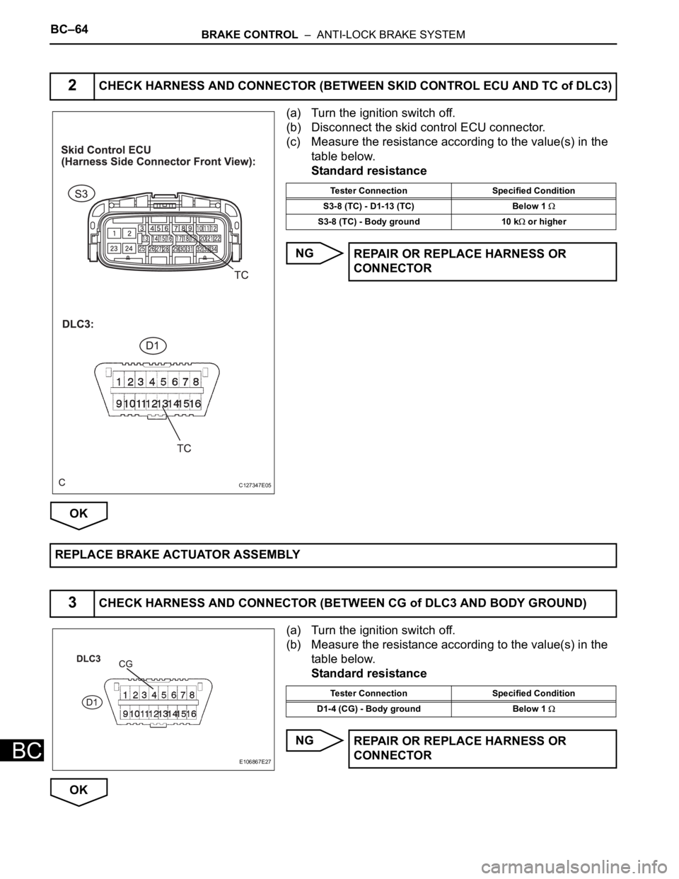
2CHECK HARNESS AND CONNECTOR (BETWEEN SKID CONTROL ECU AND TC of DLC3)
C127347E05
Tester Connection Specified Condition
S3-8 (TC) - D1-13 (TC) Below 1
S3-8 (TC) - Body ground 10 k or higher
REPAIR OR REPLACE HARNESS OR
CONNECTOR
REPLACE BRAKE ACTUATOR ASSEMBLY
3CHECK HARNESS AND CONNECTOR (BETWEEN CG of DLC3 AND BODY GROUND)
E106867E27
Tester Connection Specified Condition
D1-4 (CG) - Body ground Below 1
REPAIR OR REPLACE HARNESS OR
CONNECTOR
Page 2426 of 3000
BRAKE CONTROL – ANTI-LOCK BRAKE SYSTEMBC–65
BC
(a) Disconnect the skid control ECU connector.
(b) Measure the resistance according to the value(s) in the
table below.
Standard resistance
NG
OK
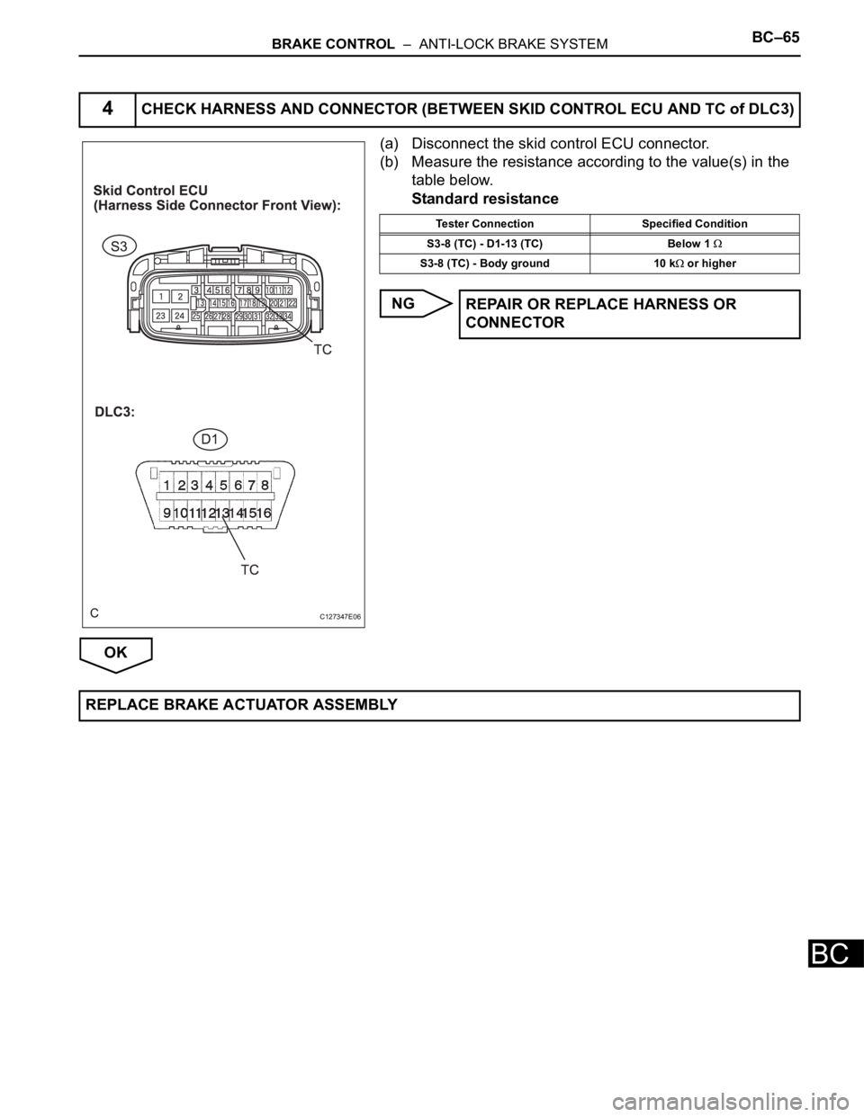
4CHECK HARNESS AND CONNECTOR (BETWEEN SKID CONTROL ECU AND TC of DLC3)
C127347E06
Tester Connection Specified Condition
S3-8 (TC) - D1-13 (TC) Below 1
S3-8 (TC) - Body ground 10 k or higher
REPAIR OR REPLACE HARNESS OR
CONNECTOR
REPLACE BRAKE ACTUATOR ASSEMBLY
Page 2427 of 3000
BC–66BRAKE CONTROL – ANTI-LOCK BRAKE SYSTEM
BC
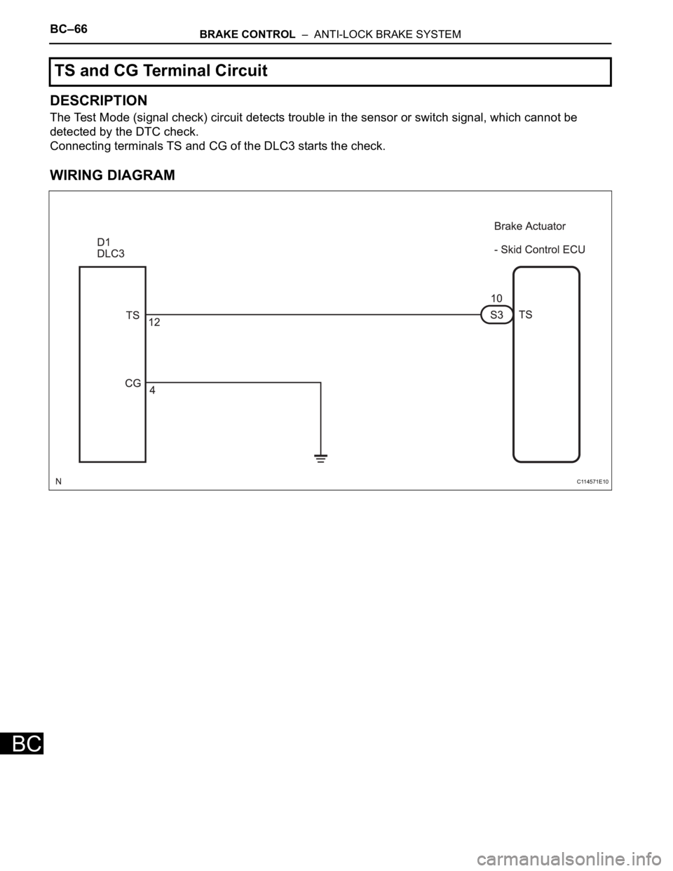
DESCRIPTION
The Test Mode (signal check) circuit detects trouble in the sensor or switch signal, which cannot be
detected by the DTC check.
Connecting terminals TS and CG of the DLC3 starts the check.
WIRING DIAGRAM
TS and CG Terminal Circuit
C114571E10
Page 2428 of 3000
BRAKE CONTROL – ANTI-LOCK BRAKE SYSTEMBC–67
BC
INSPECTION PROCEDURE
(a) Turn the ignition switch off.
(b) Disconnect the skid control ECU connector.
(c) Measure the resistance according to the value(s) in the
table below.
Standard resistance
NG
OK
(a) Measure the resistance according to the value(s) in the
table below.
Standard resistance
NG
OK
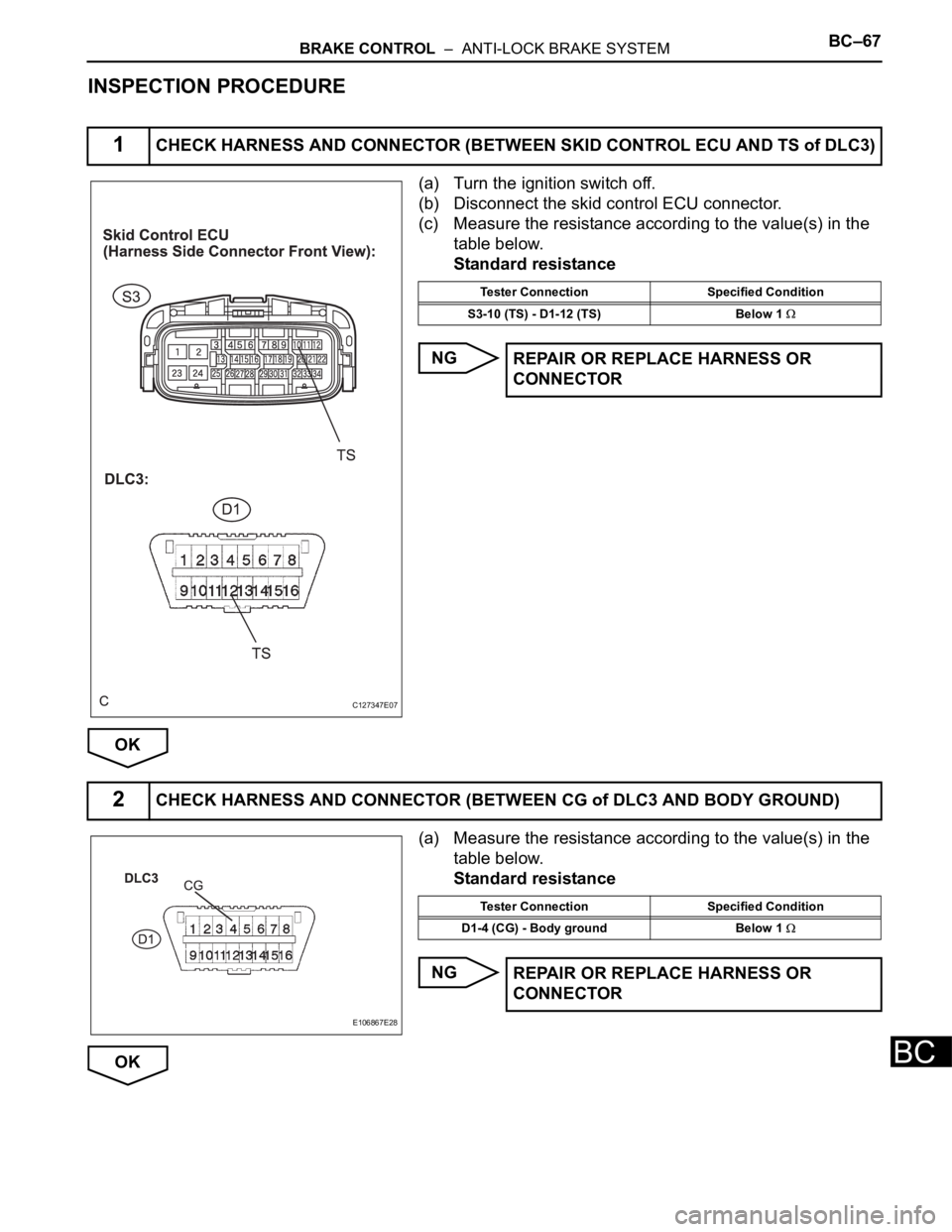
1CHECK HARNESS AND CONNECTOR (BETWEEN SKID CONTROL ECU AND TS of DLC3)
C127347E07
Tester Connection Specified Condition
S3-10 (TS) - D1-12 (TS) Below 1
REPAIR OR REPLACE HARNESS OR
CONNECTOR
2CHECK HARNESS AND CONNECTOR (BETWEEN CG of DLC3 AND BODY GROUND)
E106867E28
Tester Connection Specified Condition
D1-4 (CG) - Body ground Below 1
REPAIR OR REPLACE HARNESS OR
CONNECTOR
Page 2429 of 3000
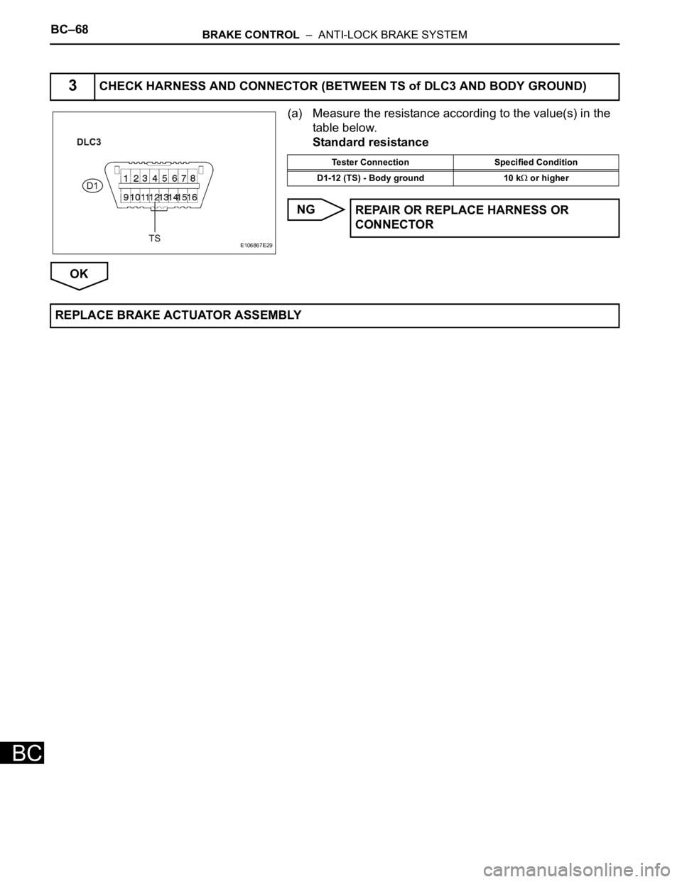
BC–68BRAKE CONTROL – ANTI-LOCK BRAKE SYSTEM
BC
(a) Measure the resistance according to the value(s) in the
table below.
Standard resistance
NG
OK
3CHECK HARNESS AND CONNECTOR (BETWEEN TS of DLC3 AND BODY GROUND)
E106867E29
Tester Connection Specified Condition
D1-12 (TS) - Body ground 10 k
or higher
REPAIR OR REPLACE HARNESS OR
CONNECTOR
REPLACE BRAKE ACTUATOR ASSEMBLY
Page 2430 of 3000

BC–14BRAKE CONTROL – ANTI-LOCK BRAKE SYSTEM
BC
FREEZE FRAME DATA
1. FREEZE FRAME DATA
(a) Whenever a DTC is detected or the ABS operates,
the skid control ECU stores the current vehicle
(sensor) state as freeze frame data.
The skid control ECU stores the number of times
(maximum: 31) the ignition switch has been turned
from OFF to the ON position since the last time the
ABS was activated.
HINT:
• Freeze frame data at the time the ABS operates:
The skid control ECU stores and updates data
whenever the ABS system operates.
When the ECU stores data at the time a DTC is
detected, the data stored during ABS operation is
erased.
(b) Connect the intelligent tester to the DLC3.
(c) Turn the ignition switch to the ON position.
(d) On the tester display, select the FREEZE FRAME
DATA.
Intelligent Tester Display Measurement Item Reference Value
VEHICLE SPD Vehicle speed readingMin.: 0 mph (0 km/h), Max.: 202 mph (326.4
km/h)
STOP LIGHT SW Stop light switch signal Stop light switch ON: ON, OFF: OFF
# IG ONNumber of operations of ignition switch ON
after memorizing freeze frame data0 to 31
SYSTEM System statusABS activated: ABS
No system activated: NO SYS
Trending: brake, headrest, wiper fluid, height adjustment, tire type, fuel pressure, roof
