TOYOTA SIENNA 2007 Service Repair Manual
Manufacturer: TOYOTA, Model Year: 2007, Model line: SIENNA, Model: TOYOTA SIENNA 2007Pages: 3000, PDF Size: 52.26 MB
Page 2811 of 3000
AC–68AIR CONDITIONING – AIR CONDITIONING SYSTEM (for Automatic Air Conditioning Sys-
tem)
AC
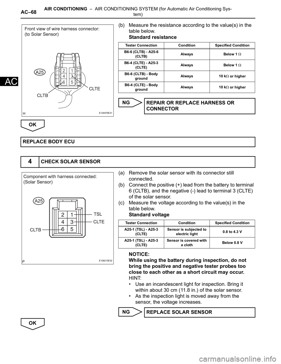
(b) Measure the resistance according to the value(s) in the
table below.
Standard resistance
NG
OK
(a) Remove the solar sensor with its connector still
connected.
(b) Connect the positive (+) lead from the battery to terminal
6 (CLTB), and the negative (-) lead to terminal 3 (CLTE)
of the solar sensor.
(c) Measure the voltage according to the value(s) in the
table below.
Standard voltage
NOTICE:
While using the battery during inspection, do not
bring the positive and negative tester probes too
close to each other as a short circuit may occur.
HINT:
• Use an incandescent light for inspection. Bring it
within about 30 cm (11.8 in.) of the solar sensor.
• As the inspection light is moved away from the
sensor, the voltage increases.
NG
OK
E124476E31
Tester Connection Condition Specified Condition
B6-6 (CLTB) - A25-6
(CLTB)Always Below 1
B6-4 (CLTE) - A25-3
(CLTE)Always Below 1
B6-6 (CLTB) - Body
groundAlways 10 k or higher
B6-4 (CLTE) - Body
groundAlways 10 k
or higher
REPAIR OR REPLACE HARNESS OR
CONNECTOR
REPLACE BODY ECU
4CHECK SOLAR SENSOR
E109215E32
Tester Connection Condition Specified Condition
A25-1 (TSL) - A25-3
(CLTE)Sensor is subjected to
electric light0.8 to 4.3 V
A25-1 (TSL) - A25-3
(CLTE)Sensor is covered with
a clothBelow 0.8 V
REPLACE SOLAR SENSOR
Page 2812 of 3000
AIR CONDITIONING – AIR CONDITIONING SYSTEM (for Automatic Air Conditioning Sys-
tem)AC–69
AC
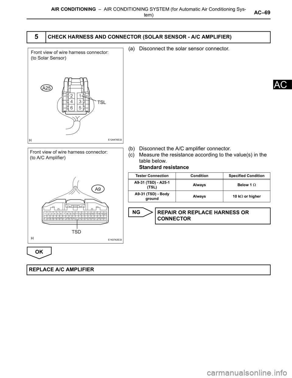
(a) Disconnect the solar sensor connector.
(b) Disconnect the A/C amplifier connector.
(c) Measure the resistance according to the value(s) in the
table below.
Standard resistance
NG
OK
5CHECK HARNESS AND CONNECTOR (SOLAR SENSOR - A/C AMPLIFIER)
E124476E33
E143742E33
Tester Connection Condition Specified Condition
A9-31 (TSD) - A25-1
(TSL)Always Below 1
A9-31 (TSD) - Body
groundAlways 10 k or higher
REPAIR OR REPLACE HARNESS OR
CONNECTOR
REPLACE A/C AMPLIFIER
Page 2813 of 3000
AC–70AIR CONDITIONING – AIR CONDITIONING SYSTEM (for Automatic Air Conditioning Sys-
tem)
AC
DESCRIPTION
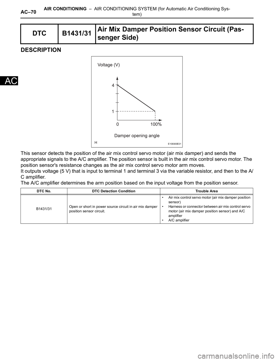
This sensor detects the position of the air mix control servo motor (air mix damper) and sends the
appropriate signals to the A/C amplifier. The position sensor is built in the air mix control servo motor. The
position sensor's resistance changes as the air mix control servo motor arm moves.
It outputs voltage (5 V) that is input to terminal 1 and terminal 3 via the variable resistor, and then to the A/
C amplifier.
The A/C amplifier determines the arm position based on the input voltage from the position sensor.
DTC B1431/31Air Mix Damper Position Sensor Circuit (Pas-
senger Side)
DTC No. DTC Detection Condition Trouble Area
B1431/31Open or short in power source circuit in air mix damper
position sensor circuit.• Air mix control servo motor (air mix damper position
sensor)
• Harness or connector between air mix control servo
motor (air mix damper position sensor) and A/C
amplifier
• A/C amplifier
E109300E01
Page 2814 of 3000
AIR CONDITIONING – AIR CONDITIONING SYSTEM (for Automatic Air Conditioning Sys-
tem)AC–71
AC
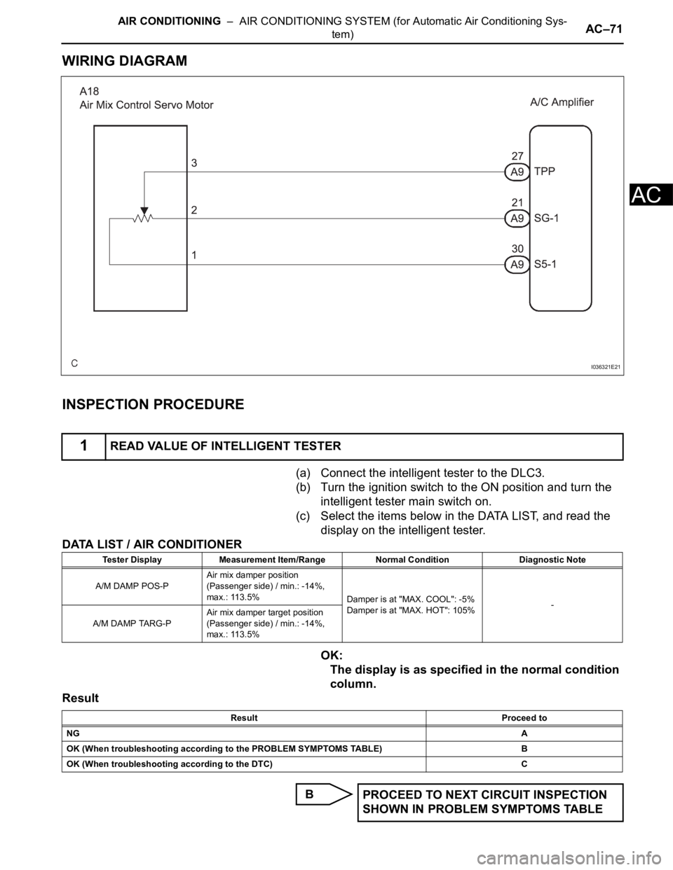
WIRING DIAGRAM
INSPECTION PROCEDURE
(a) Connect the intelligent tester to the DLC3.
(b) Turn the ignition switch to the ON position and turn the
intelligent tester main switch on.
(c) Select the items below in the DATA LIST, and read the
display on the intelligent tester.
DATA LIST / AIR CONDITIONER
OK:
The display is as specified in the normal condition
column.
Result
B
1READ VALUE OF INTELLIGENT TESTER
I036321E21
Tester Display Measurement Item/Range Normal Condition Diagnostic Note
A/M DAMP POS-PAir mix damper position
(Passenger side) / min.: -14%,
max.: 113.5%
Damper is at "MAX. COOL": -5%
Damper is at "MAX. HOT": 105%-
A/M DAMP TARG-PAir mix damper target position
(Passenger side) / min.: -14%,
max.: 113.5%
Result Proceed to
NGA
OK (When troubleshooting according to the PROBLEM SYMPTOMS TABLE) B
OK (When troubleshooting according to the DTC) C
PROCEED TO NEXT CIRCUIT INSPECTION
SHOWN IN PROBLEM SYMPTOMS TABLE
Page 2815 of 3000
AC–72AIR CONDITIONING – AIR CONDITIONING SYSTEM (for Automatic Air Conditioning Sys-
tem)
AC
C
A
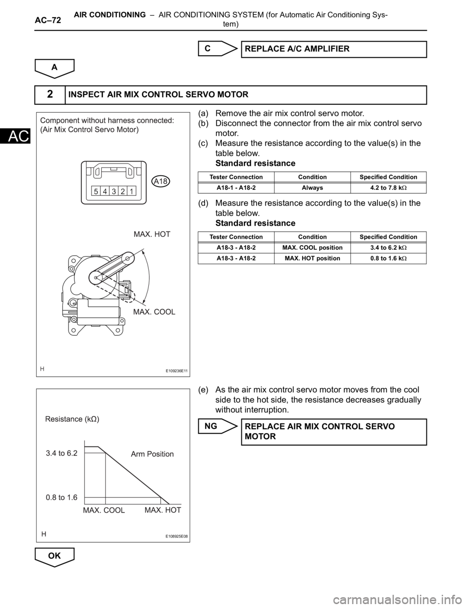
(a) Remove the air mix control servo motor.
(b) Disconnect the connector from the air mix control servo
motor.
(c) Measure the resistance according to the value(s) in the
table below.
Standard resistance
(d) Measure the resistance according to the value(s) in the
table below.
Standard resistance
(e) As the air mix control servo motor moves from the cool
side to the hot side, the resistance decreases gradually
without interruption.
NG
OKREPLACE A/C AMPLIFIER
2INSPECT AIR MIX CONTROL SERVO MOTOR
E109236E11
Tester Connection Condition Specified Condition
A18-1 - A18-2 Always 4.2 to 7.8 k
Tester Connection Condition Specified Condition
A18-3 - A18-2 MAX. COOL position 3.4 to 6.2 k
A18-3 - A18-2 MAX. HOT position 0.8 to 1.6 k
E108925E08
REPLACE AIR MIX CONTROL SERVO
MOTOR
Page 2816 of 3000
AIR CONDITIONING – AIR CONDITIONING SYSTEM (for Automatic Air Conditioning Sys-
tem)AC–73
AC
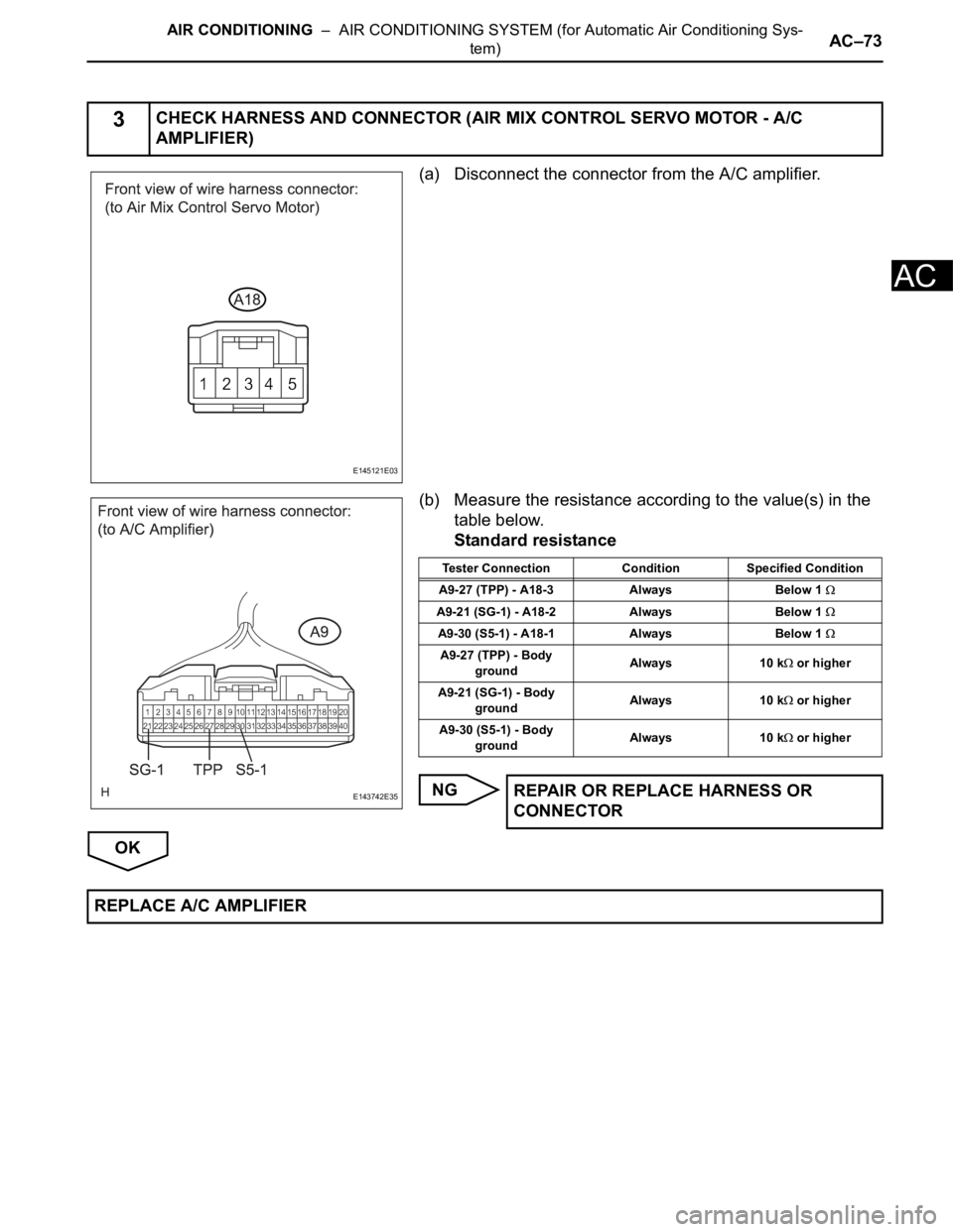
(a) Disconnect the connector from the A/C amplifier.
(b) Measure the resistance according to the value(s) in the
table below.
Standard resistance
NG
OK
3CHECK HARNESS AND CONNECTOR (AIR MIX CONTROL SERVO MOTOR - A/C
AMPLIFIER)
E145121E03
E143742E35
Tester Connection Condition Specified Condition
A9-27 (TPP) - A18-3 Always Below 1
A9-21 (SG-1) - A18-2 Always Below 1
A9-30 (S5-1) - A18-1 Always Below 1
A9-27 (TPP) - Body
groundAlways 10 k or higher
A9-21 (SG-1) - Body
groundAlways 10 k
or higher
A9-30 (S5-1) - Body
groundAlways 10 k
or higher
REPAIR OR REPLACE HARNESS OR
CONNECTOR
REPLACE A/C AMPLIFIER
Page 2817 of 3000
AC–74AIR CONDITIONING – AIR CONDITIONING SYSTEM (for Automatic Air Conditioning Sys-
tem)
AC
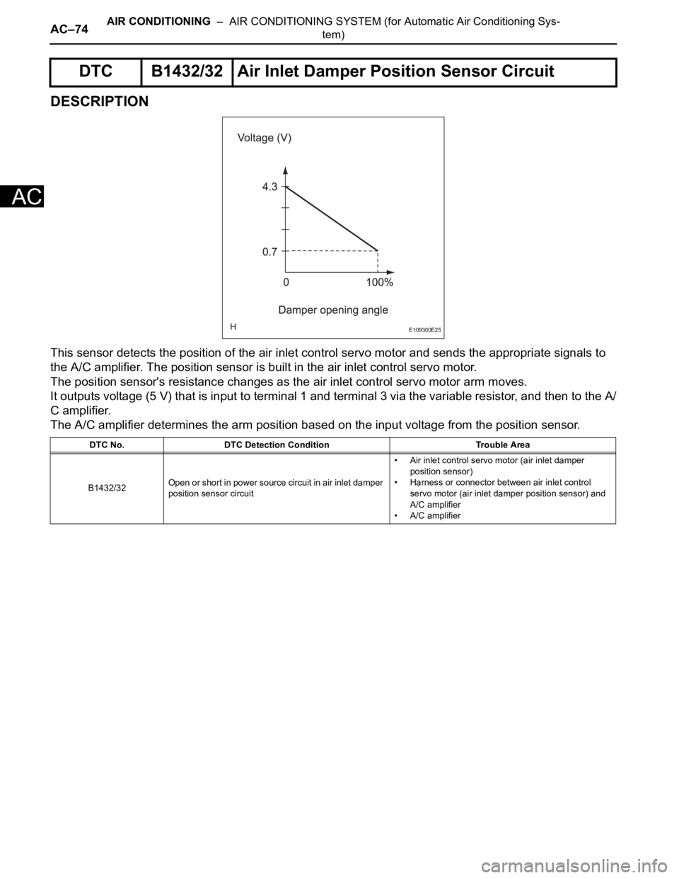
DESCRIPTION
This sensor detects the position of the air inlet control servo motor and sends the appropriate signals to
the A/C amplifier. The position sensor is built in the air inlet control servo motor.
The position sensor's resistance changes as the air inlet control servo motor arm moves.
It outputs voltage (5 V) that is input to terminal 1 and terminal 3 via the variable resistor, and then to the A/
C amplifier.
The A/C amplifier determines the arm position based on the input voltage from the position sensor.
DTC B1432/32 Air Inlet Damper Position Sensor Circuit
DTC No. DTC Detection Condition Trouble Area
B1432/32Open or short in power source circuit in air inlet damper
position sensor circuit• Air inlet control servo motor (air inlet damper
position sensor)
• Harness or connector between air inlet control
servo motor (air inlet damper position sensor) and
A/C amplifier
• A/C amplifier
E109300E25
Page 2818 of 3000
AIR CONDITIONING – AIR CONDITIONING SYSTEM (for Automatic Air Conditioning Sys-
tem)AC–75
AC
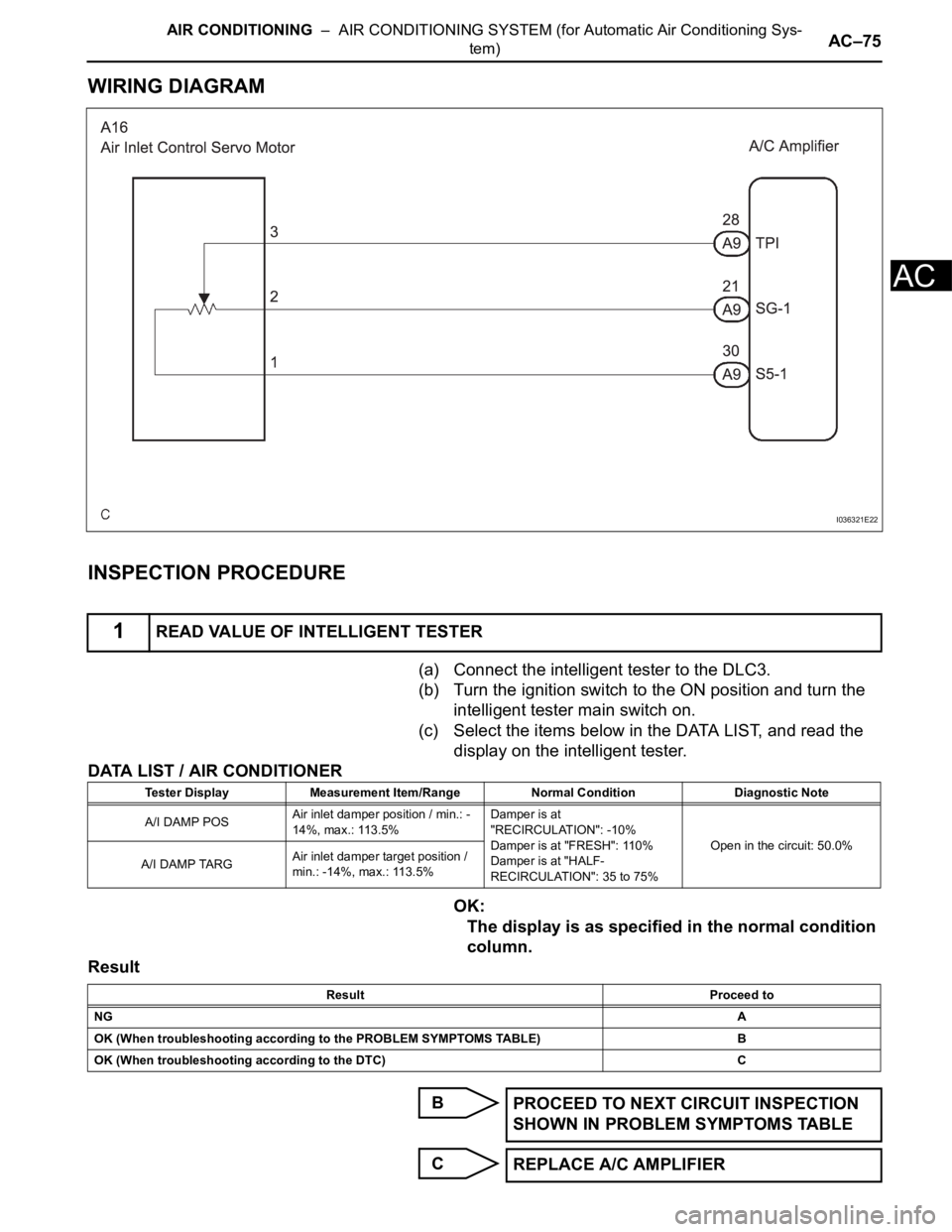
WIRING DIAGRAM
INSPECTION PROCEDURE
(a) Connect the intelligent tester to the DLC3.
(b) Turn the ignition switch to the ON position and turn the
intelligent tester main switch on.
(c) Select the items below in the DATA LIST, and read the
display on the intelligent tester.
DATA LIST / AIR CONDITIONER
OK:
The display is as specified in the normal condition
column.
Result
B
C
1READ VALUE OF INTELLIGENT TESTER
I036321E22
Tester Display Measurement Item/Range Normal Condition Diagnostic Note
A/I DAMP POSAir inlet damper position / min.: -
14%, max.: 113.5%Damper is at
"RECIRCULATION": -10%
Damper is at "FRESH": 110%
Damper is at "HALF-
RECIRCULATION": 35 to 75%Open in the circuit: 50.0%
A/I DAMP TARGAir inlet damper target position /
min.: -14%, max.: 113.5%
Result Proceed to
NGA
OK (When troubleshooting according to the PROBLEM SYMPTOMS TABLE) B
OK (When troubleshooting according to the DTC) C
PROCEED TO NEXT CIRCUIT INSPECTION
SHOWN IN PROBLEM SYMPTOMS TABLE
REPLACE A/C AMPLIFIER
Page 2819 of 3000
AC–76AIR CONDITIONING – AIR CONDITIONING SYSTEM (for Automatic Air Conditioning Sys-
tem)
AC
A
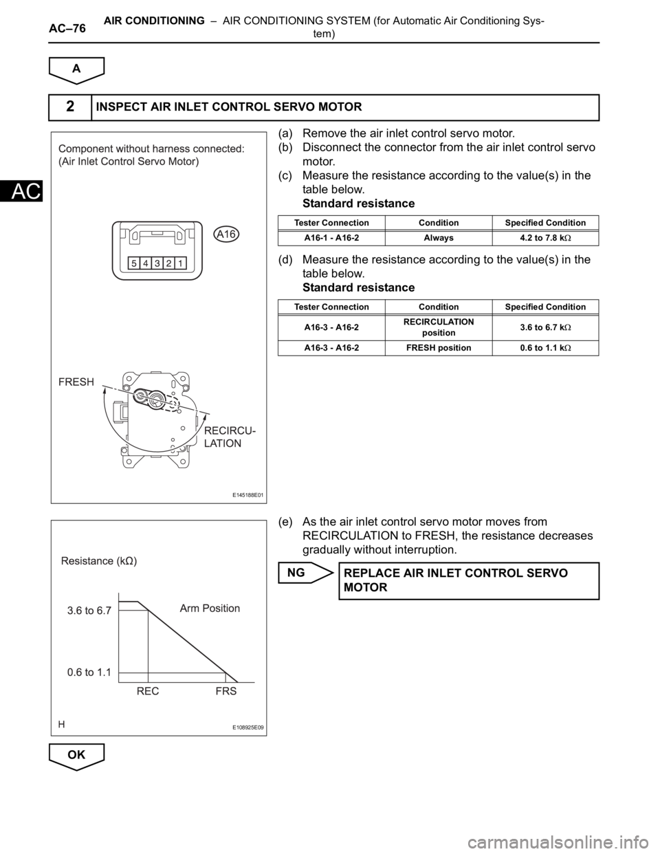
(a) Remove the air inlet control servo motor.
(b) Disconnect the connector from the air inlet control servo
motor.
(c) Measure the resistance according to the value(s) in the
table below.
Standard resistance
(d) Measure the resistance according to the value(s) in the
table below.
Standard resistance
(e) As the air inlet control servo motor moves from
RECIRCULATION to FRESH, the resistance decreases
gradually without interruption.
NG
OK
2INSPECT AIR INLET CONTROL SERVO MOTOR
E145188E01
Tester Connection Condition Specified Condition
A16-1 - A16-2 Always 4.2 to 7.8 k
Tester Connection Condition Specified Condition
A16-3 - A16-2RECIRCULATION
position3.6 to 6.7 k
A16-3 - A16-2 FRESH position 0.6 to 1.1 k
E108925E09
REPLACE AIR INLET CONTROL SERVO
MOTOR
Page 2820 of 3000
AIR CONDITIONING – AIR CONDITIONING SYSTEM (for Automatic Air Conditioning Sys-
tem)AC–77
AC
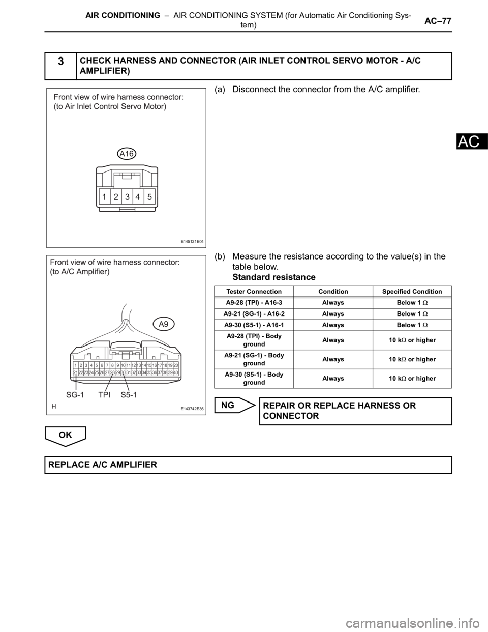
(a) Disconnect the connector from the A/C amplifier.
(b) Measure the resistance according to the value(s) in the
table below.
Standard resistance
NG
OK
3CHECK HARNESS AND CONNECTOR (AIR INLET CONTROL SERVO MOTOR - A/C
AMPLIFIER)
E145121E04
E143742E36
Tester Connection Condition Specified Condition
A9-28 (TPI) - A16-3 Always Below 1
A9-21 (SG-1) - A16-2 Always Below 1
A9-30 (S5-1) - A16-1 Always Below 1
A9-28 (TPI) - Body
groundAlways 10 k or higher
A9-21 (SG-1) - Body
groundAlways 10 k
or higher
A9-30 (S5-1) - Body
groundAlways 10 k
or higher
REPAIR OR REPLACE HARNESS OR
CONNECTOR
REPLACE A/C AMPLIFIER