TOYOTA SIENNA 2007 Service Repair Manual
Manufacturer: TOYOTA, Model Year: 2007, Model line: SIENNA, Model: TOYOTA SIENNA 2007Pages: 3000, PDF Size: 52.26 MB
Page 2801 of 3000
AC–58AIR CONDITIONING – AIR CONDITIONING SYSTEM (for Automatic Air Conditioning Sys-
tem)
AC
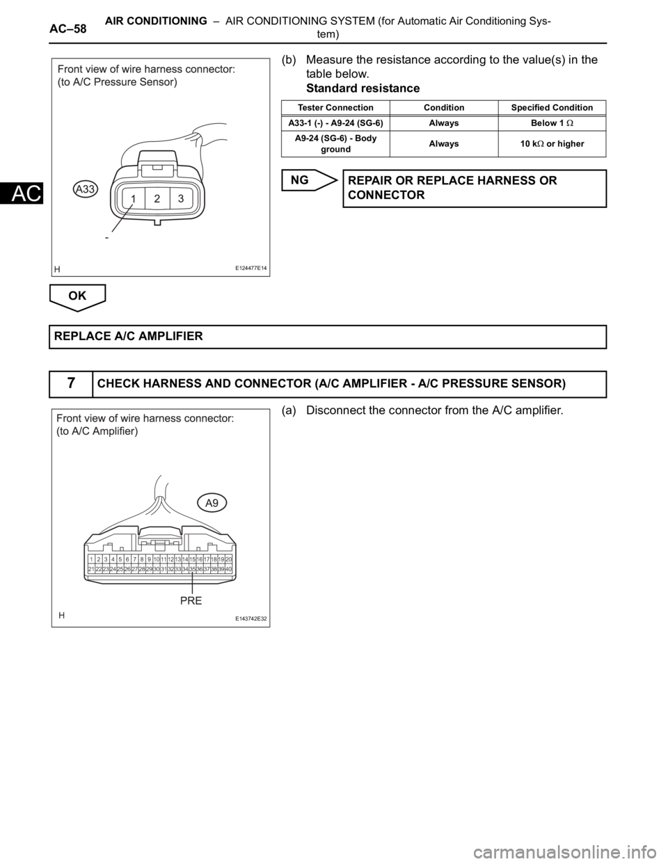
(b) Measure the resistance according to the value(s) in the
table below.
Standard resistance
NG
OK
(a) Disconnect the connector from the A/C amplifier.
E124477E14
Tester Connection Condition Specified Condition
A33-1 (-) - A9-24 (SG-6) Always Below 1
A9-24 (SG-6) - Body
groundAlways 10 k or higher
REPAIR OR REPLACE HARNESS OR
CONNECTOR
REPLACE A/C AMPLIFIER
7CHECK HARNESS AND CONNECTOR (A/C AMPLIFIER - A/C PRESSURE SENSOR)
E143742E32
Page 2802 of 3000
AIR CONDITIONING – AIR CONDITIONING SYSTEM (for Automatic Air Conditioning Sys-
tem)AC–59
AC
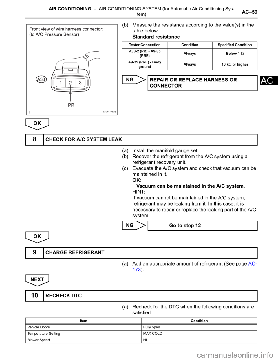
(b) Measure the resistance according to the value(s) in the
table below.
Standard resistance
NG
OK
(a) Install the manifold gauge set.
(b) Recover the refrigerant from the A/C system using a
refrigerant recovery unit.
(c) Evacuate the A/C system and check that vacuum can be
maintained in it.
OK:
Vacuum can be maintained in the A/C system.
HINT:
If vacuum cannot be maintained in the A/C system,
refrigerant may be leaking from it. In this case, it is
necessary to repair or replace the leaking part of the A/C
system.
NG
OK
(a) Add an appropriate amount of refrigerant (See page AC-
173).
NEXT
(a) Recheck for the DTC when the following conditions are
satisfied.
E124477E15
Tester Connection Condition Specified Condition
A33-2 (PR) - A9-35
(PRE)Always Below 1
A9-35 (PRE) - Body
groundAlways 10 k or higher
REPAIR OR REPLACE HARNESS OR
CONNECTOR
8CHECK FOR A/C SYSTEM LEAK
Go to step 12
9CHARGE REFRIGERANT
10RECHECK DTC
Item Condition
Vehicle Doors Fully open
Temperature Setting MAX COLD
Blower Speed HI
Page 2803 of 3000

AC–60AIR CONDITIONING – AIR CONDITIONING SYSTEM (for Automatic Air Conditioning Sys-
tem)
AC
NOTICE:
If refrigerant pressure on the high pressure side
becomes high, the DTC will be set. It is necessary to
measure the voltage for a certain amount of time
(approximately 10 minutes) because the DTC may be
set after the A/C operates for a while.
HINT:
When the outside air temperature is low (below -1.5
C
(29.3
F)), the compressor stops due to operation of the
ambient temperature sensor and the evaporator
temperature sensor to prevent the evaporator from
freezing. In this case, perform the inspection in a warm
indoor environment.
Result
NOTICE:
If the DTC was set due to an insufficient or excessive
amount of refrigerant, the problem may have been
solved after performing the previous step. However,
the root cause of insufficient refrigerant may be
refrigerant leaks. The root cause of excessive
refrigerant may be adding refrigerant when the level
was insufficient. Therefore, identify and repair the
area where refrigerant leaks from as necessary.
B
A
(a) Install the manifold gauge set.
(b) Disconnect the connector from the A/C pressure sensor.
A/C Switch ON
R/F Switch RECIRCULATION
Interior Temperature 25 to 35
C (77 to 95F)
Engine Speed 2000 rpmItem Condition
Result Proceed to
DTC B1423 is output A
DTC B1423 is not output B
END
11INSPECT A/C PRESSURE SENSOR
Page 2804 of 3000
AIR CONDITIONING – AIR CONDITIONING SYSTEM (for Automatic Air Conditioning Sys-
tem)AC–61
AC
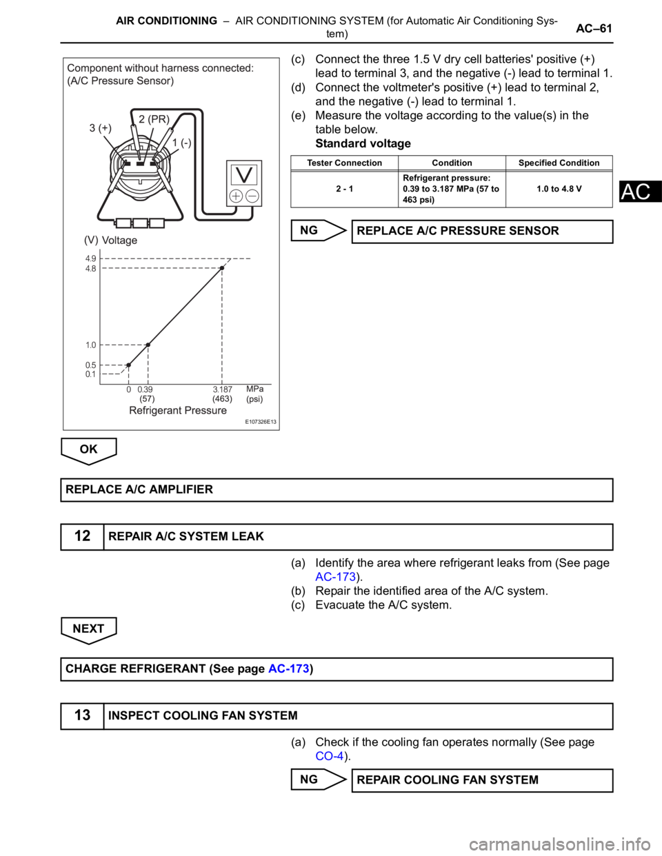
(c) Connect the three 1.5 V dry cell batteries' positive (+)
lead to terminal 3, and the negative (-) lead to terminal 1.
(d) Connect the voltmeter's positive (+) lead to terminal 2,
and the negative (-) lead to terminal 1.
(e) Measure the voltage according to the value(s) in the
table below.
Standard voltage
NG
OK
(a) Identify the area where refrigerant leaks from (See page
AC-173).
(b) Repair the identified area of the A/C system.
(c) Evacuate the A/C system.
NEXT
(a) Check if the cooling fan operates normally (See page
CO-4).
NG
E107326E13
Tester Connection Condition Specified Condition
2 - 1Refrigerant pressure:
0.39 to 3.187 MPa (57 to
463 psi)1.0 to 4.8 V
REPLACE A/C PRESSURE SENSOR
REPLACE A/C AMPLIFIER
12REPAIR A/C SYSTEM LEAK
CHARGE REFRIGERANT (See page AC-173)
13INSPECT COOLING FAN SYSTEM
REPAIR COOLING FAN SYSTEM
Page 2805 of 3000

AC–62AIR CONDITIONING – AIR CONDITIONING SYSTEM (for Automatic Air Conditioning Sys-
tem)
AC
OK
(a) Use a refrigerant recovery unit to recover refrigerant.
(b) Evacuate the A/C system.
(c) Add an appropriate amount of refrigerant (See page AC-
173).
HINT:
If refrigerant is added and the system has not been
properly evacuated (insufficient vacuum time), moisture
in the air remaining in the system will freeze in the
expansion valve, blocking the flow on the high pressure
side. Therefore, in order to confirm the problem, recover
the refrigerant and properly evacuate the system. Add an
appropriate amount of refrigerant, and check for the
DTC.
NEXT
(a) Recheck for the DTC when the following conditions are
satisfied.
NOTICE:
If refrigerant pressure on the high pressure side
becomes high, the DTC will be set. It is necessary to
measure the voltage for a certain amount of time
(approximately 10 minutes) because the DTC may be
set after the A/C operates for a while.
HINT:
• When the outside air temperature is low (below -1.5
C
(29.3
F)), the compressor stops due to operation of
the ambient temperature sensor and the evaporator
temperature sensor to prevent the evaporator from
freezing. In this case, perform the inspection in a
warm indoor environment.
14CHARGE REFRIGERANT
15RECHECK DTC
Item Condition
Vehicle Doors Fully open
Temperature Setting MAX COLD
Blower Speed HI
A/C Switch ON
R/F Switch RECIRCULATION
Interior Temperature 25 to 35
C (77 to 95F)
Engine Speed 2000 rpm
Page 2806 of 3000
AIR CONDITIONING – AIR CONDITIONING SYSTEM (for Automatic Air Conditioning Sys-
tem)AC–63
AC
• If refrigerant is added and the system has not been
properly evacuated (insufficient vacuum time),
moisture in the air remaining in the system will freeze
in the expansion valve, blocking the flow on the high
pressure side. Therefore, in order to confirm the
problem, recover the refrigerant and properly
evacuate the system. Add an appropriate amount of
refrigerant, and check for the DTC. If the DTC is not
output after this work, it indicates that the cooler dryer
in the condenser is not able to absorb moisture in the
refrigerant cycle. In this case, it is necessary to
replace the cooler dryer in order to complete the
repair.
Result
B
A
(a) Replace the expansion valve with a normal one (See
page AC-186).
HINT:
Replace the expansion valve with a normal one because
the expansion valve is either stuck or clogged.
NEXT
(a) Add an appropriate amount of refrigerant (See page AC-
173).
NEXT
(a) Recheck for the DTC when the following conditions are
satisfied.
Result Proceed to
DTC B1423 is output A
DTC B1423 is not output B
REPLACE COOLER DRYER
16REPLACE EXPANSION VALVE
17CHARGE REFRIGERANT
18RECHECK DTC
Item Condition
Vehicle Doors Fully open
Temperature Setting MAX COLD
Blower Speed HI
A/C Switch ON
R/F Switch RECIRCULATION
Interior Temperature 25 to 35
C (77 to 95F)
Engine Speed 2000 rpm
Page 2807 of 3000
AC–64AIR CONDITIONING – AIR CONDITIONING SYSTEM (for Automatic Air Conditioning Sys-
tem)
AC
NOTICE:
If refrigerant pressure on the high pressure side
becomes high, the DTC will be set. It is necessary to
measure the voltage for a certain amount of time
(approximately 10 minutes) because the DTC may be
set after the A/C operates for a while.
HINT:
• When the outside air temperature is low (below -1.5
C
(29.3
F)), the compressor stops due to operation of
the ambient temperature sensor and the evaporator
temperature sensor to prevent the evaporator from
freezing. In this case, perform the inspection in a
warm indoor environment.
• If refrigerant pressure is not normal after replacing the
expansion valve with a normal one, the condenser or
pipes may be clogged due to dirt, dust or other
contaminant. In this case, clean or replace the
condenser or pipes.
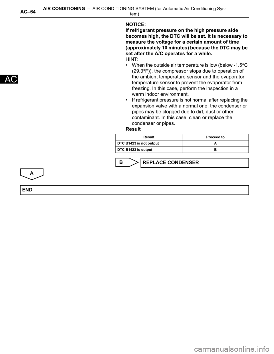
Result
B
A
Result Proceed to
DTC B1423 is not output A
DTC B1423 is output B
REPLACE CONDENSER
END
Page 2808 of 3000
AIR CONDITIONING – AIR CONDITIONING SYSTEM (for Automatic Air Conditioning Sys-
tem)AC–65
AC
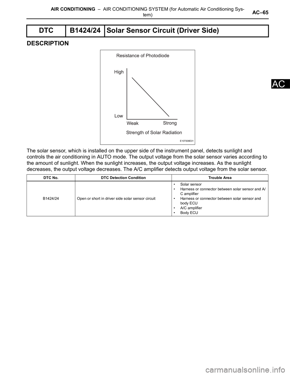
DESCRIPTION
The solar sensor, which is installed on the upper side of the instrument panel, detects sunlight and
controls the air conditioning in AUTO mode. The output voltage from the solar sensor varies according to
the amount of sunlight. When the sunlight increases, the output voltage increases. As the sunlight
decreases, the output voltage decreases. The A/C amplifier detects output voltage from the solar sensor.
DTC B1424/24 Solar Sensor Circuit (Driver Side)
DTC No. DTC Detection Condition Trouble Area
B1424/24 Open or short in driver side solar sensor circuit•Solar sensor
• Harness or connector between solar sensor and A/
C amplifier
• Harness or connector between solar sensor and
body ECU
• A/C amplifier
• Body ECU
E107008E01
Page 2809 of 3000
AC–66AIR CONDITIONING – AIR CONDITIONING SYSTEM (for Automatic Air Conditioning Sys-
tem)
AC
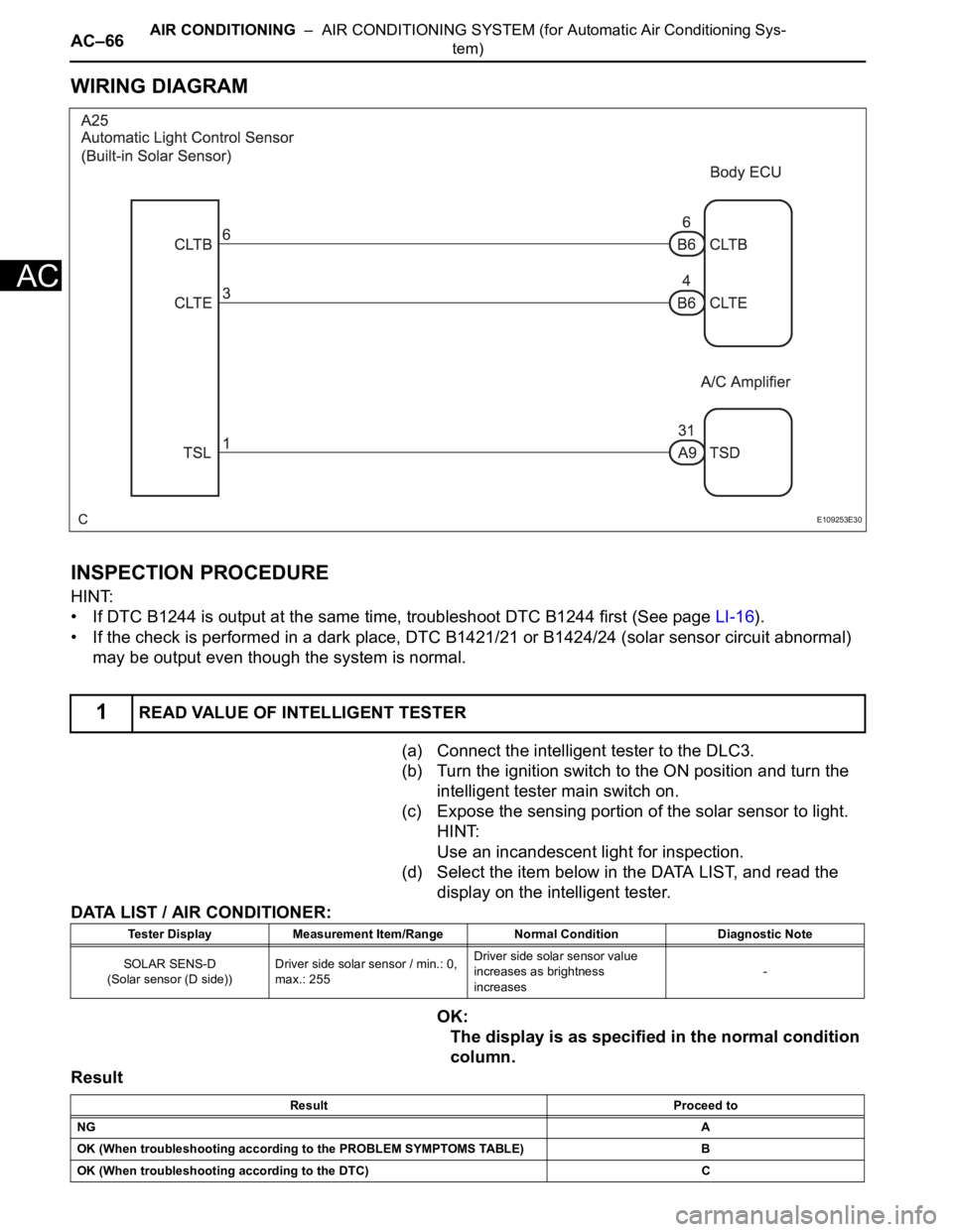
WIRING DIAGRAM
INSPECTION PROCEDURE
HINT:
• If DTC B1244 is output at the same time, troubleshoot DTC B1244 first (See page LI-16).
• If the check is performed in a dark place, DTC B1421/21 or B1424/24 (solar sensor circuit abnormal)
may be output even though the system is normal.
(a) Connect the intelligent tester to the DLC3.
(b) Turn the ignition switch to the ON position and turn the
intelligent tester main switch on.
(c) Expose the sensing portion of the solar sensor to light.
HINT:
Use an incandescent light for inspection.
(d) Select the item below in the DATA LIST, and read the
display on the intelligent tester.
DATA LIST / AIR CONDITIONER:
OK:
The display is as specified in the normal condition
column.
Result
1READ VALUE OF INTELLIGENT TESTER
E109253E30
Tester Display Measurement Item/Range Normal Condition Diagnostic Note
SOLAR SENS-D
(Solar sensor (D side))Driver side solar sensor / min.: 0,
max.: 255Driver side solar sensor value
increases as brightness
increases-
Result Proceed to
NGA
OK (When troubleshooting according to the PROBLEM SYMPTOMS TABLE) B
OK (When troubleshooting according to the DTC) C
Page 2810 of 3000
AIR CONDITIONING – AIR CONDITIONING SYSTEM (for Automatic Air Conditioning Sys-
tem)AC–67
AC
B
C
A
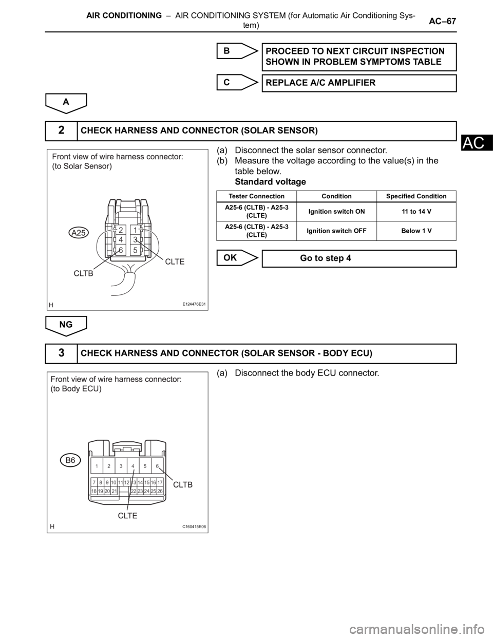
(a) Disconnect the solar sensor connector.
(b) Measure the voltage according to the value(s) in the
table below.
Standard voltage
OK
NG
(a) Disconnect the body ECU connector.PROCEED TO NEXT CIRCUIT INSPECTION
SHOWN IN PROBLEM SYMPTOMS TABLE
REPLACE A/C AMPLIFIER
2CHECK HARNESS AND CONNECTOR (SOLAR SENSOR)
E124476E31
Tester Connection Condition Specified Condition
A25-6 (CLTB) - A25-3
(CLTE)Ignition switch ON 11 to 14 V
A25-6 (CLTB) - A25-3
(CLTE)Ignition switch OFF Below 1 V
Go to step 4
3CHECK HARNESS AND CONNECTOR (SOLAR SENSOR - BODY ECU)
C160415E06