TOYOTA SIENNA 2007 Service Repair Manual
Manufacturer: TOYOTA, Model Year: 2007, Model line: SIENNA, Model: TOYOTA SIENNA 2007Pages: 3000, PDF Size: 52.26 MB
Page 2781 of 3000
AIR CONDITIONING – AIR CONDITIONING SYSTEM (for Automatic Air Conditioning Sys-
tem)AC–35
AC
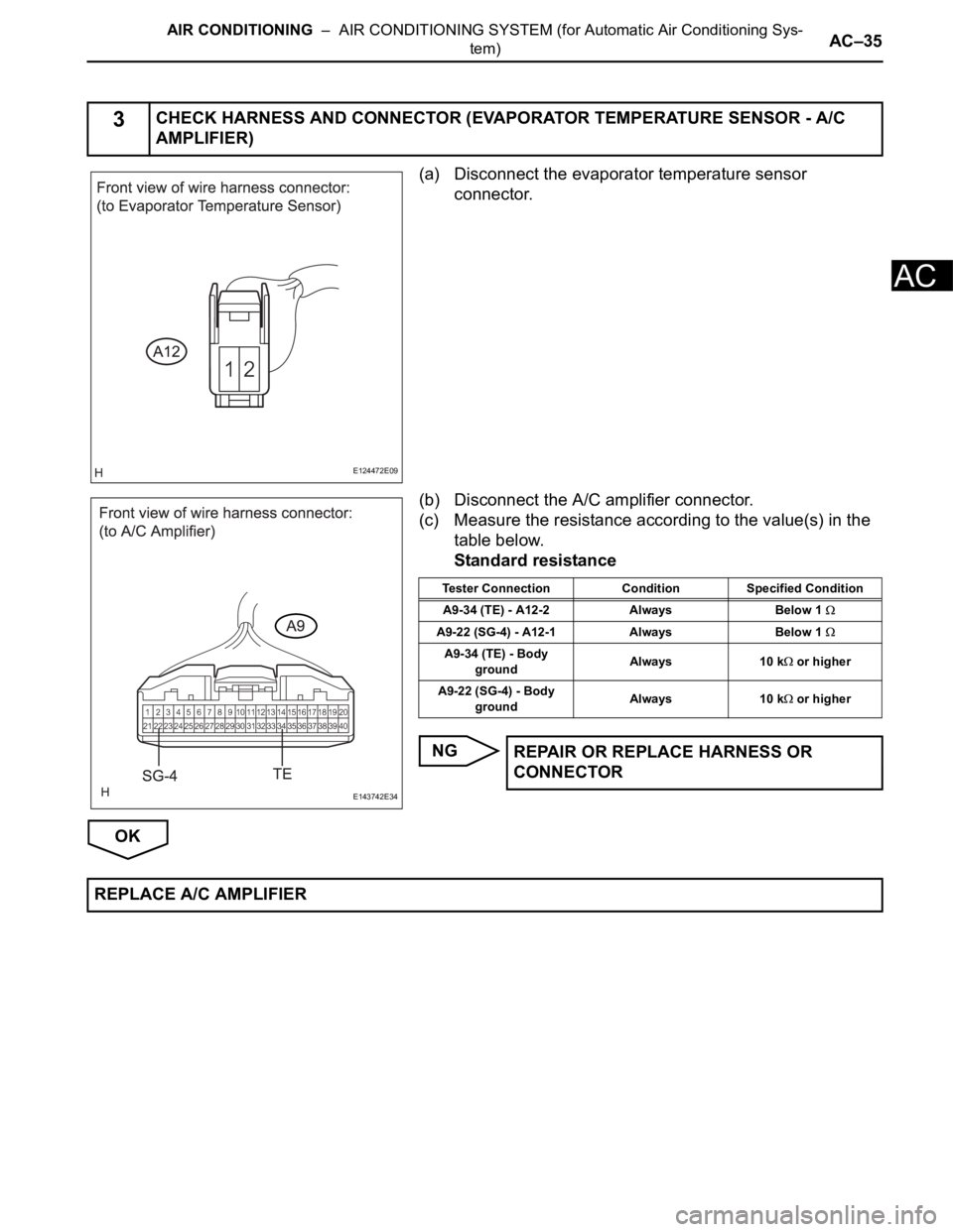
(a) Disconnect the evaporator temperature sensor
connector.
(b) Disconnect the A/C amplifier connector.
(c) Measure the resistance according to the value(s) in the
table below.
Standard resistance
NG
OK
3CHECK HARNESS AND CONNECTOR (EVAPORATOR TEMPERATURE SENSOR - A/C
AMPLIFIER)
E124472E09
E143742E34
Tester Connection Condition Specified Condition
A9-34 (TE) - A12-2 Always Below 1
A9-22 (SG-4) - A12-1 Always Below 1
A9-34 (TE) - Body
groundAlways 10 k or higher
A9-22 (SG-4) - Body
groundAlways 10 k
or higher
REPAIR OR REPLACE HARNESS OR
CONNECTOR
REPLACE A/C AMPLIFIER
Page 2782 of 3000
AC–36AIR CONDITIONING – AIR CONDITIONING SYSTEM (for Automatic Air Conditioning Sys-
tem)
AC
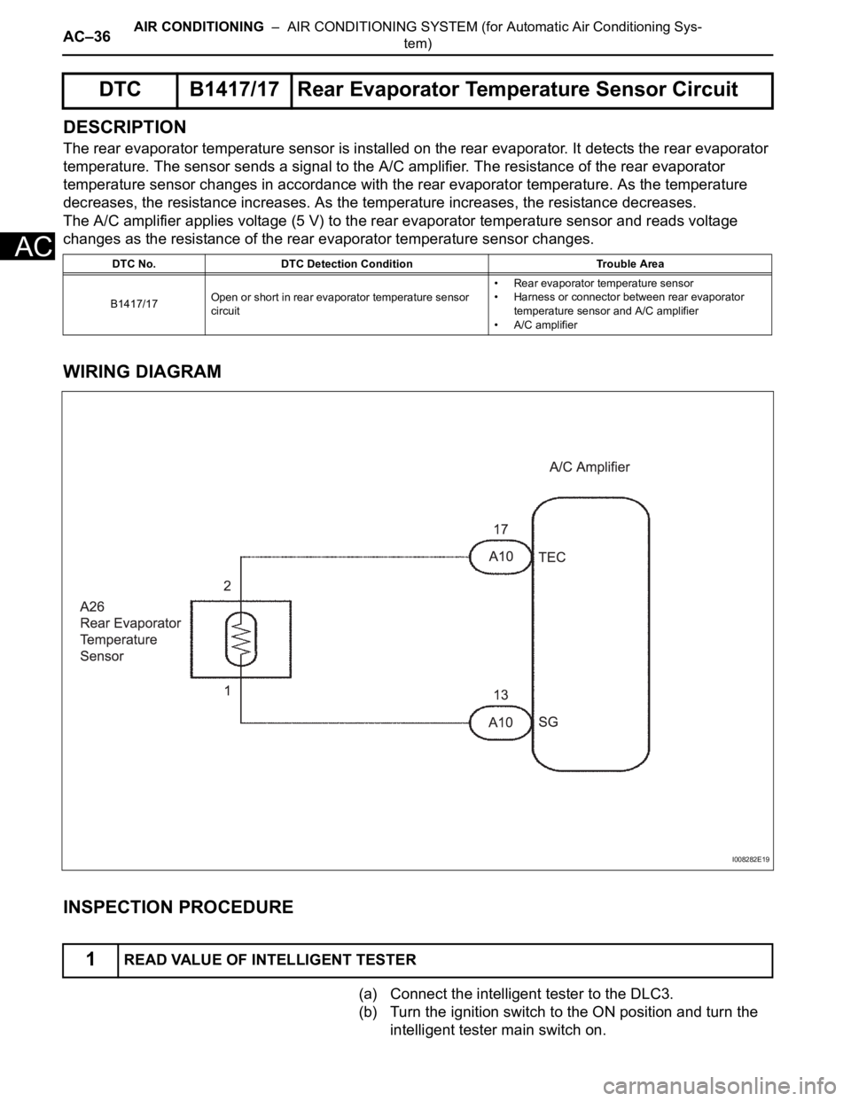
DESCRIPTION
The rear evaporator temperature sensor is installed on the rear evaporator. It detects the rear evaporator
temperature. The sensor sends a signal to the A/C amplifier. The resistance of the rear evaporator
temperature sensor changes in accordance with the rear evaporator temperature. As the temperature
decreases, the resistance increases. As the temperature increases, the resistance decreases.
The A/C amplifier applies voltage (5 V) to the rear evaporator temperature sensor and reads voltage
changes as the resistance of the rear evaporator temperature sensor changes.
WIRING DIAGRAM
INSPECTION PROCEDURE
(a) Connect the intelligent tester to the DLC3.
(b) Turn the ignition switch to the ON position and turn the
intelligent tester main switch on.
DTC B1417/17 Rear Evaporator Temperature Sensor Circuit
DTC No. DTC Detection Condition Trouble Area
B1417/17Open or short in rear evaporator temperature sensor
circuit• Rear evaporator temperature sensor
• Harness or connector between rear evaporator
temperature sensor and A/C amplifier
• A/C amplifier
1READ VALUE OF INTELLIGENT TESTER
I008282E19
Page 2783 of 3000
AIR CONDITIONING – AIR CONDITIONING SYSTEM (for Automatic Air Conditioning Sys-
tem)AC–37
AC
(c) Select the item below in the DATA LIST, and read the
display on the intelligent tester.
DATA LIST / AIR CONDITIONER:
OK:
The display is as specified in the normal condition
column.
Result
B
C
A
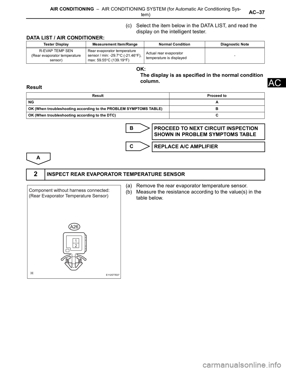
(a) Remove the rear evaporator temperature sensor.
(b) Measure the resistance according to the value(s) in the
table below.
Tester Display Measurement Item/Range Normal Condition Diagnostic Note
R-EVAP TEMP SEN
(Rear evaporator temperature
sensor)Rear evaporator temperature
sensor / min: -29.7
C (-21.46F),
max: 59.55
C (139.19F)Actual rear evaporator
temperature is displayed-
Result Proceed to
NGA
OK (When troubleshooting according to the PROBLEM SYMPTOMS TABLE) B
OK (When troubleshooting according to the DTC) C
PROCEED TO NEXT CIRCUIT INSPECTION
SHOWN IN PROBLEM SYMPTOMS TABLE
REPLACE A/C AMPLIFIER
2INSPECT REAR EVAPORATOR TEMPERATURE SENSOR
E112577E07
Page 2784 of 3000
AC–38AIR CONDITIONING – AIR CONDITIONING SYSTEM (for Automatic Air Conditioning Sys-
tem)
AC
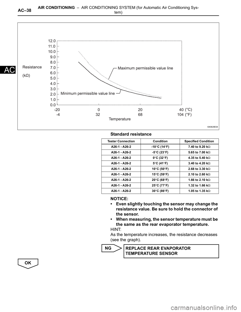
Standard resistance
NOTICE:
• Even slightly touching the sensor may change the
resistance value. Be sure to hold the connector of
the sensor.
• When measuring, the sensor temperature must be
the same as the rear evaporator temperature.
HINT:
As the temperature increases, the resistance decreases
(see the graph).
NG
OK
I040629E04
Tester Connection Condition Specified Condition
A26-1 - A26-2 -10
C (14F) 7.40 to 9.20 k
A26-1 - A26-2 -5C (23F) 5.65 to 7.00 k
A26-1 - A26-2 0C (32F) 4.35 to 5.40 k
A26-1 - A26-2 5C (41F) 3.40 to 4.20 k
A26-1 - A26-2 10C (50F) 2.68 to 3.30 k
A26-1 - A26-2 15C (59F) 2.10 to 2.60 k
A26-1 - A26-2 20C (68F) 1.66 to 2.10 k
A26-1 - A26-2 25C (77F) 1.32 to 1.66 k
A26-1 - A26-2 30C (86F) 1.05 to 1.35 k
REPLACE REAR EVAPORATOR
TEMPERATURE SENSOR
Page 2785 of 3000
AIR CONDITIONING – AIR CONDITIONING SYSTEM (for Automatic Air Conditioning Sys-
tem)AC–39
AC
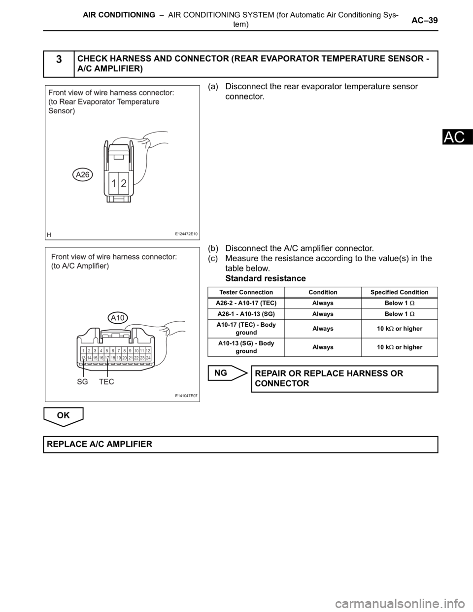
(a) Disconnect the rear evaporator temperature sensor
connector.
(b) Disconnect the A/C amplifier connector.
(c) Measure the resistance according to the value(s) in the
table below.
Standard resistance
NG
OK
3CHECK HARNESS AND CONNECTOR (REAR EVAPORATOR TEMPERATURE SENSOR -
A/C AMPLIFIER)
E124472E10
E141047E07
Tester Connection Condition Specified Condition
A26-2 - A10-17 (TEC) Always Below 1
A26-1 - A10-13 (SG) Always Below 1
A10-17 (TEC) - Body
groundAlways 10 k or higher
A10-13 (SG) - Body
groundAlways 10 k
or higher
REPAIR OR REPLACE HARNESS OR
CONNECTOR
REPLACE A/C AMPLIFIER
Page 2786 of 3000
AIR CONDITIONING – AIR CONDITIONING SYSTEM (for Automatic Air Conditioning Sys-
tem)AC–43
AC
DESCRIPTION
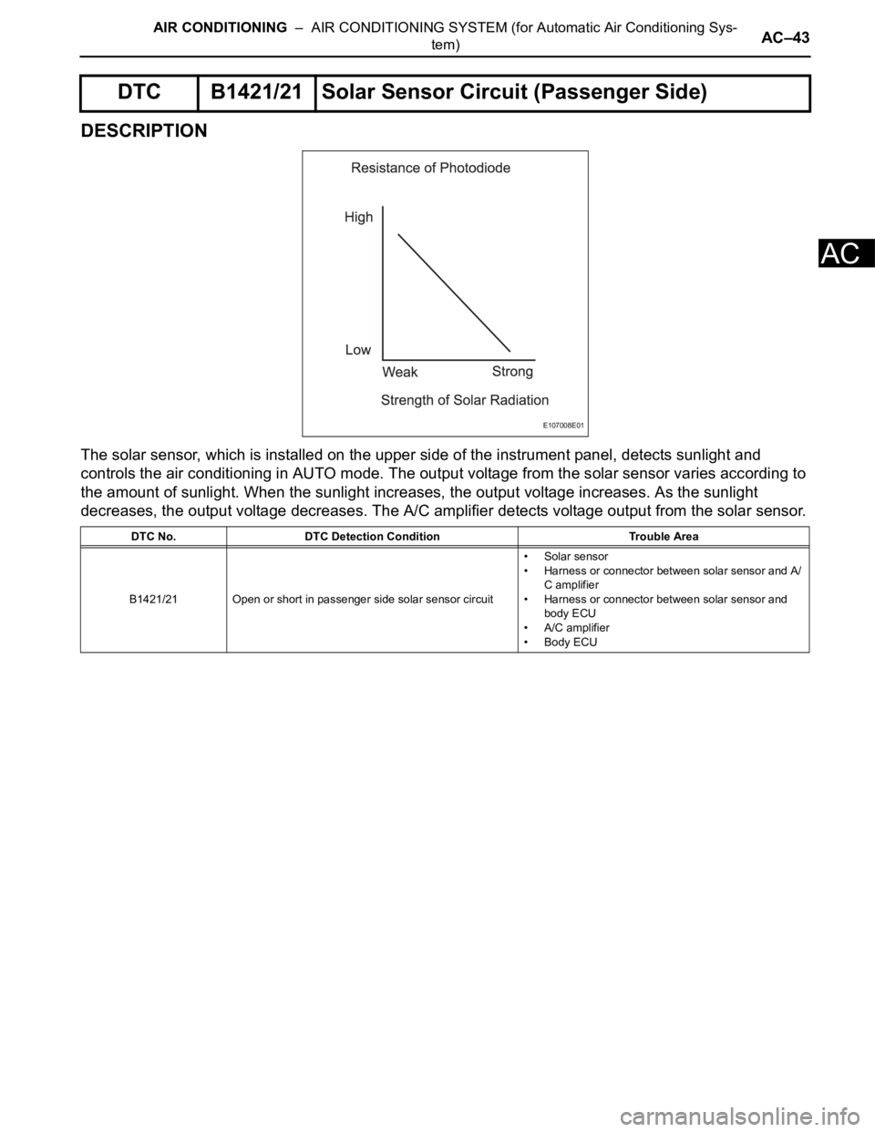
The solar sensor, which is installed on the upper side of the instrument panel, detects sunlight and
controls the air conditioning in AUTO mode. The output voltage from the solar sensor varies according to
the amount of sunlight. When the sunlight increases, the output voltage increases. As the sunlight
decreases, the output voltage decreases. The A/C amplifier detects voltage output from the solar sensor.
DTC B1421/21 Solar Sensor Circuit (Passenger Side)
DTC No. DTC Detection Condition Trouble Area
B1421/21 Open or short in passenger side solar sensor circuit•Solar sensor
• Harness or connector between solar sensor and A/
C amplifier
• Harness or connector between solar sensor and
body ECU
• A/C amplifier
• Body ECU
E107008E01
Page 2787 of 3000
AC–44AIR CONDITIONING – AIR CONDITIONING SYSTEM (for Automatic Air Conditioning Sys-
tem)
AC
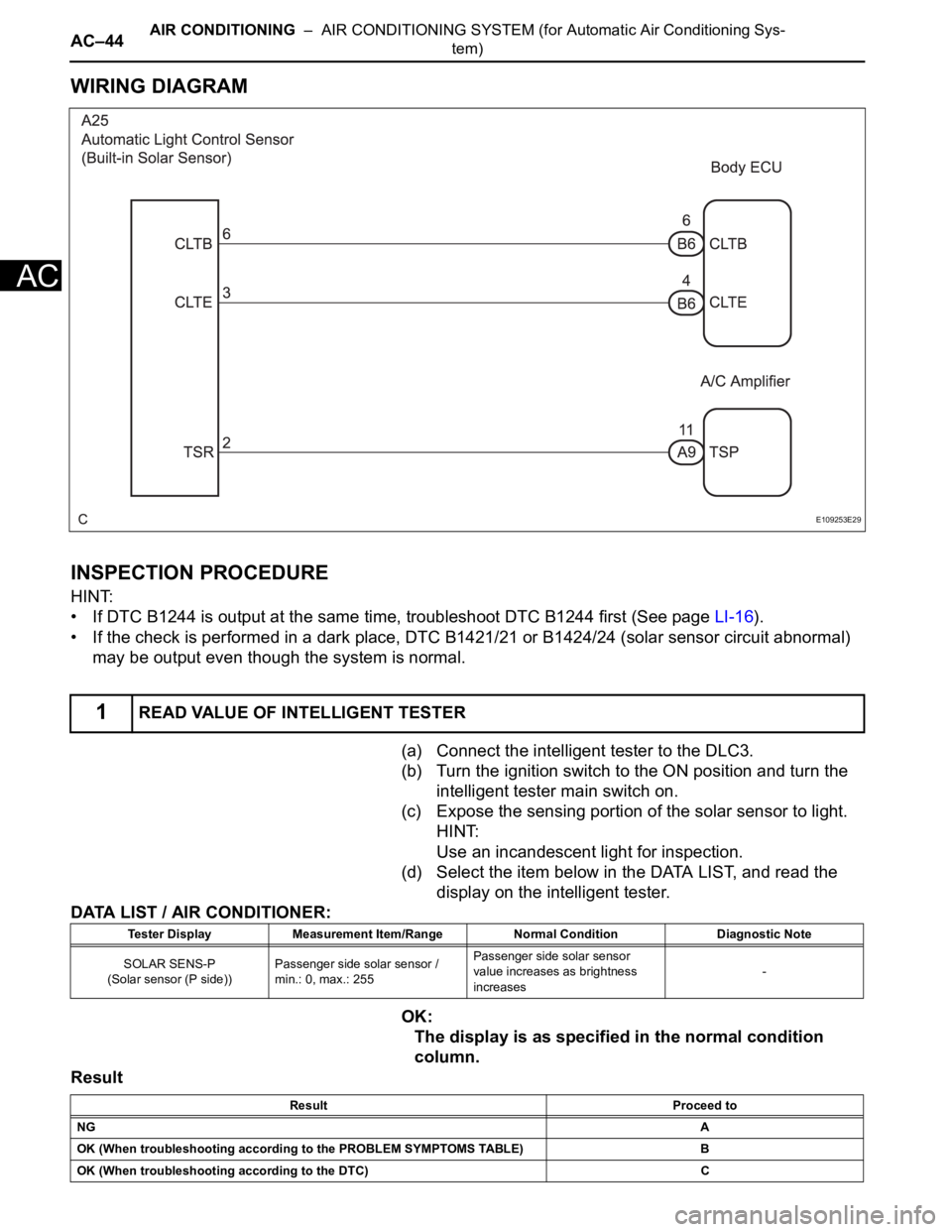
WIRING DIAGRAM
INSPECTION PROCEDURE
HINT:
• If DTC B1244 is output at the same time, troubleshoot DTC B1244 first (See page LI-16).
• If the check is performed in a dark place, DTC B1421/21 or B1424/24 (solar sensor circuit abnormal)
may be output even though the system is normal.
(a) Connect the intelligent tester to the DLC3.
(b) Turn the ignition switch to the ON position and turn the
intelligent tester main switch on.
(c) Expose the sensing portion of the solar sensor to light.
HINT:
Use an incandescent light for inspection.
(d) Select the item below in the DATA LIST, and read the
display on the intelligent tester.
DATA LIST / AIR CONDITIONER:
OK:
The display is as specified in the normal condition
column.
Result
1READ VALUE OF INTELLIGENT TESTER
E109253E29
Tester Display Measurement Item/Range Normal Condition Diagnostic Note
SOLAR SENS-P
(Solar sensor (P side))Passenger side solar sensor /
min.: 0, max.: 255Passenger side solar sensor
value increases as brightness
increases-
Result Proceed to
NGA
OK (When troubleshooting according to the PROBLEM SYMPTOMS TABLE) B
OK (When troubleshooting according to the DTC) C
Page 2788 of 3000
AIR CONDITIONING – AIR CONDITIONING SYSTEM (for Automatic Air Conditioning Sys-
tem)AC–45
AC
B
C
A
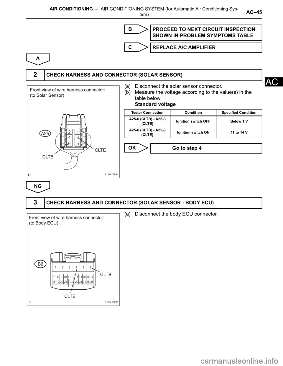
(a) Disconnect the solar sensor connector.
(b) Measure the voltage according to the value(s) in the
table below.
Standard voltage
OK
NG
(a) Disconnect the body ECU connector.PROCEED TO NEXT CIRCUIT INSPECTION
SHOWN IN PROBLEM SYMPTOMS TABLE
REPLACE A/C AMPLIFIER
2CHECK HARNESS AND CONNECTOR (SOLAR SENSOR)
E124476E31
Tester Connection Condition Specified Condition
A25-6 (CLTB) - A25-3
(CLTE)Ignition switch OFF Below 1 V
A25-6 (CLTB) - A25-3
(CLTE)Ignition switch ON 11 to 14 V
Go to step 4
3CHECK HARNESS AND CONNECTOR (SOLAR SENSOR - BODY ECU)
C160415E05
Page 2789 of 3000
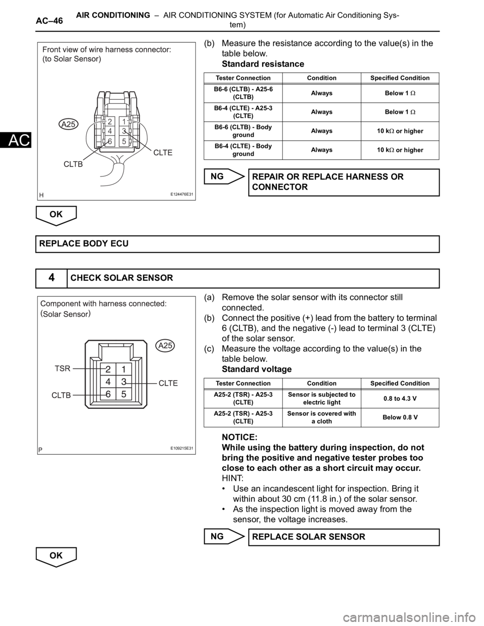
AC–46AIR CONDITIONING – AIR CONDITIONING SYSTEM (for Automatic Air Conditioning Sys-
tem)
AC
(b) Measure the resistance according to the value(s) in the
table below.
Standard resistance
NG
OK
(a) Remove the solar sensor with its connector still
connected.
(b) Connect the positive (+) lead from the battery to terminal
6 (CLTB), and the negative (-) lead to terminal 3 (CLTE)
of the solar sensor.
(c) Measure the voltage according to the value(s) in the
table below.
Standard voltage
NOTICE:
While using the battery during inspection, do not
bring the positive and negative tester probes too
close to each other as a short circuit may occur.
HINT:
• Use an incandescent light for inspection. Bring it
within about 30 cm (11.8 in.) of the solar sensor.
• As the inspection light is moved away from the
sensor, the voltage increases.
NG
OK
E124476E31
Tester Connection Condition Specified Condition
B6-6 (CLTB) - A25-6
(CLTB)Always Below 1
B6-4 (CLTE) - A25-3
(CLTE)Always Below 1
B6-6 (CLTB) - Body
groundAlways 10 k or higher
B6-4 (CLTE) - Body
groundAlways 10 k
or higher
REPAIR OR REPLACE HARNESS OR
CONNECTOR
REPLACE BODY ECU
4CHECK SOLAR SENSOR
E109215E31
Tester Connection Condition Specified Condition
A25-2 (TSR) - A25-3
(CLTE)Sensor is subjected to
electric light0.8 to 4.3 V
A25-2 (TSR) - A25-3
(CLTE)Sensor is covered with
a clothBelow 0.8 V
REPLACE SOLAR SENSOR
Page 2790 of 3000

AIR CONDITIONING – AIR CONDITIONING SYSTEM (for Automatic Air Conditioning Sys-
tem)AC–47
AC
(a) Disconnect the solar sensor connector.
(b) Disconnect the A/C amplifier connector.
(c) Measure the resistance according to the value(s) in the
table below.
Standard resistance
NG
OK
5CHECK HARNESS AND CONNECTOR (SOLAR SENSOR - A/C AMPLIFIER)
E124476E32
E143742E28
Tester Connection Condition Specified Condition
A9-11 (TSP) - A25-2
(TSR)Always Below 1
A9-11 (TSP) - Body
groundAlways 10 k or higher
REPAIR OR REPLACE HARNESS OR
CONNECTOR
REPLACE A/C AMPLIFIER