TOYOTA SIENNA 2007 Service Repair Manual
Manufacturer: TOYOTA, Model Year: 2007, Model line: SIENNA, Model: TOYOTA SIENNA 2007Pages: 3000, PDF Size: 52.26 MB
Page 2851 of 3000
AC–108AIR CONDITIONING – AIR CONDITIONING SYSTEM (for Automatic Air Conditioning Sys-
tem)
AC
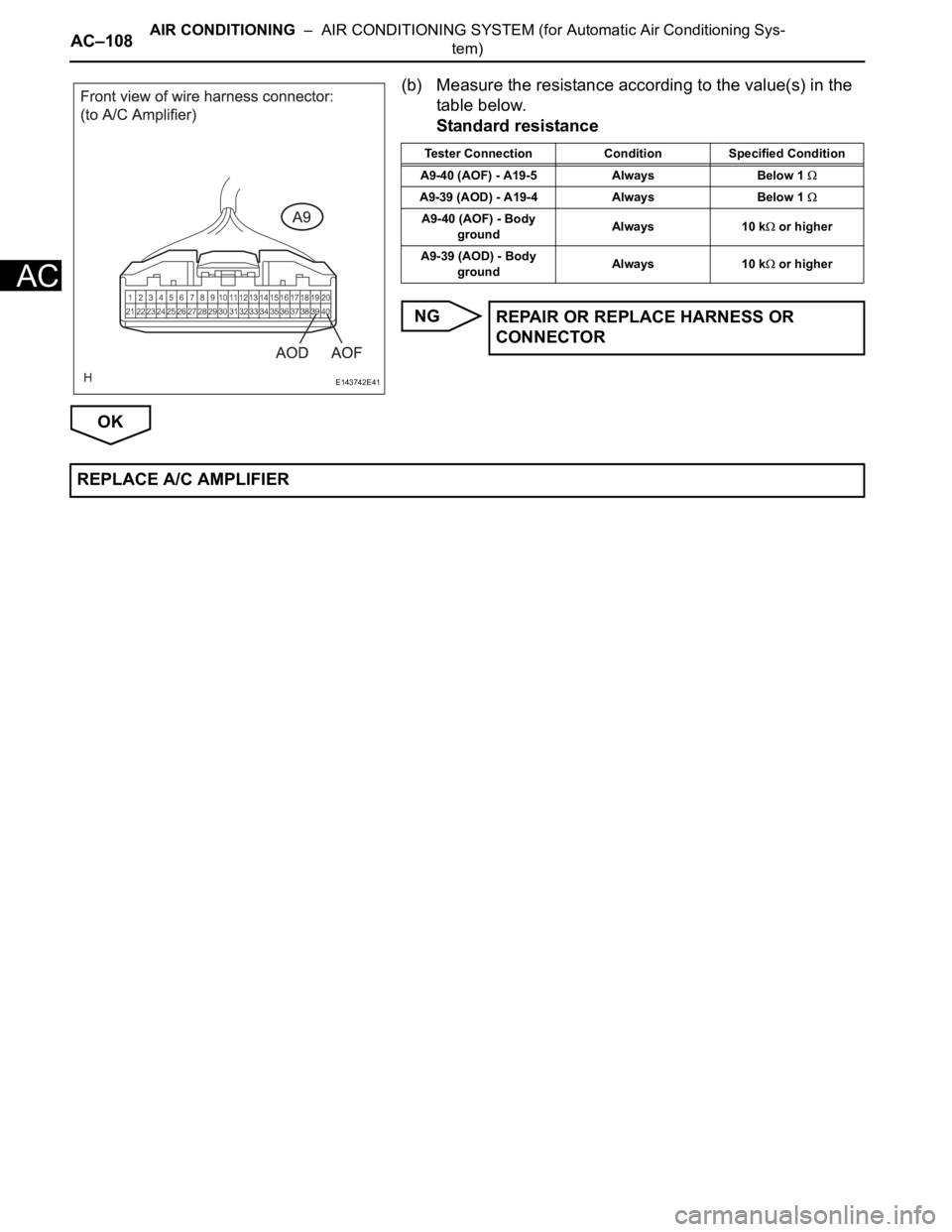
(b) Measure the resistance according to the value(s) in the
table below.
Standard resistance
NG
OK
E143742E41
Tester Connection Condition Specified Condition
A9-40 (AOF) - A19-5 Always Below 1
A9-39 (AOD) - A19-4 Always Below 1
A9-40 (AOF) - Body
groundAlways 10 k or higher
A9-39 (AOD) - Body
groundAlways 10 k
or higher
REPAIR OR REPLACE HARNESS OR
CONNECTOR
REPLACE A/C AMPLIFIER
Page 2852 of 3000
AIR CONDITIONING – AIR CONDITIONING SYSTEM (for Automatic Air Conditioning Sys-
tem)AC–109
AC
DESCRIPTION
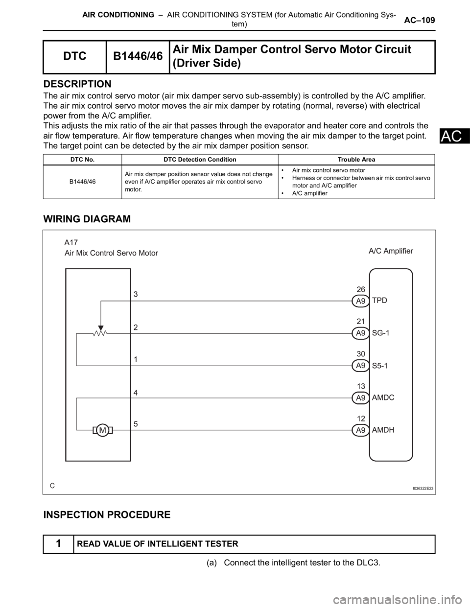
The air mix control servo motor (air mix damper servo sub-assembly) is controlled by the A/C amplifier.
The air mix control servo motor moves the air mix damper by rotating (normal, reverse) with electrical
power from the A/C amplifier.
This adjusts the mix ratio of the air that passes through the evaporator and heater core and controls the
air flow temperature. Air flow temperature changes when moving the air mix damper to the target point.
The target point can be detected by the air mix damper position sensor.
WIRING DIAGRAM
INSPECTION PROCEDURE
(a) Connect the intelligent tester to the DLC3.
DTC B1446/46Air Mix Damper Control Servo Motor Circuit
(Driver Side)
DTC No. DTC Detection Condition Trouble Area
B1446/46Air mix damper position sensor value does not change
even if A/C amplifier operates air mix control servo
motor.• Air mix control servo motor
• Harness or connector between air mix control servo
motor and A/C amplifier
• A/C amplifier
1READ VALUE OF INTELLIGENT TESTER
I036322E23
Page 2853 of 3000
AC–110AIR CONDITIONING – AIR CONDITIONING SYSTEM (for Automatic Air Conditioning Sys-
tem)
AC
(b) Turn the ignition switch to the ON position and turn the
intelligent tester main switch on.
(c) Select the items below in the DATA LIST, and read the
display on the intelligent tester.
DATA LIST / AIR CONDITIONER
OK:
When the target position is "MAX. COOL" (-5%),
the actual opening angle is 19.0% or less.
When the target position is "MAX. HOT" (105%),
the actual opening angle is 81.0% or more.
Result
B
C
A
(a) Connect the intelligent tester to the DLC3.
(b) Turn the ignition switch to the ON position and turn the
intelligent tester main switch on.
(c) Select the item below in the ACTIVE TEST and then
check the air flow temperature by hand.
ACTIVE TEST / AIR CONDITIONER
OK:
When the lever is moved to the "MAX. HOT" side,
warm air comes out.
When the lever is moved to the "MAX. COOL" side,
cool air comes out.
Result
B
Tester Display Measurement Item/Range Normal Condition Diagnostic Note
A/M DAMP POS-DAir mix damper position (Driver
side) / min.: -14%, max.: 113.5%
Damper is at "MAX. COOL": -5%
Damper is at "MAX. HOT": 105%-
A/M DAMP TARG-DAir mix damper target position
(Driver side) / min.: -14%, max.:
113.5%
Result Proceed to
NGA
OK (When troubleshooting according to the PROBLEM SYMPTOM TABLE)B
OK (When troubleshooting according to the DTC) C
PROCEED TO NEXT CIRCUIT INSPECTION
SHOWN IN PROBLEM SYMPTOMS TABLE
REPLACE A/C AMPLIFIER
2PERFORM ACTIVE TEST BY INTELLIGENT TESTER
Tester Display Test Part Control Range Diagnostic Note
AIR MIX DAMP-D Air mix damper (Driver side) min.: -14%, max.: 113.5% -
Result Proceed to
NGA
OK (When troubleshooting according to the PROBLEM SYMPTOM TABLE)B
OK (When troubleshooting according to the DTC) C
PROCEED TO NEXT CIRCUIT INSPECTION
SHOWN IN PROBLEM SYMPTOMS TABLE
Page 2854 of 3000
AIR CONDITIONING – AIR CONDITIONING SYSTEM (for Automatic Air Conditioning Sys-
tem)AC–111
AC
C
A
(a) Enter the actuator check mode (See page AC-15).
(b) Press the DEF switch and change to the step operation.
(c) Check the air flow temperature by hand.
OK:
Air flow temperature changes in accordance with
each display code.
Result
B
C
AREPLACE A/C AMPLIFIER
3PERFORM ACTUATOR CHECK
Display Code Air Mix Damper Operation
0 "COOL" side (-5%)
1 "COOL" side (-5%)
2 "COOL" side (-5%)
3 "COOL" side (-5%)
4 "COOL"/"HOT" (50% opened)
5 "COOL"/"HOT" (50% opened)
6 "HOT" side (105%)
7 "HOT" side (105%)
8 "HOT" side (105%)
9 "HOT" side (105%)
Result Proceed to
NGA
OK (When troubleshooting according to the PROBLEM SYMPTOM TABLE)B
OK (When troubleshooting according to the DTC) C
PROCEED TO NEXT CIRCUIT INSPECTION
SHOWN IN PROBLEM SYMPTOMS TABLE
REPLACE A/C AMPLIFIER
Page 2855 of 3000
AC–112AIR CONDITIONING – AIR CONDITIONING SYSTEM (for Automatic Air Conditioning Sys-
tem)
AC
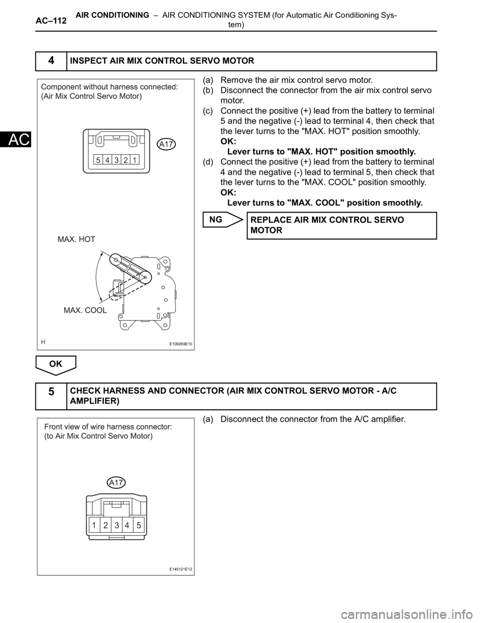
(a) Remove the air mix control servo motor.
(b) Disconnect the connector from the air mix control servo
motor.
(c) Connect the positive (+) lead from the battery to terminal
5 and the negative (-) lead to terminal 4, then check that
the lever turns to the "MAX. HOT" position smoothly.
OK:
Lever turns to "MAX. HOT" position smoothly.
(d) Connect the positive (+) lead from the battery to terminal
4 and the negative (-) lead to terminal 5, then check that
the lever turns to the "MAX. COOL" position smoothly.
OK:
Lever turns to "MAX. COOL" position smoothly.
NG
OK
(a) Disconnect the connector from the A/C amplifier.
4INSPECT AIR MIX CONTROL SERVO MOTOR
E109269E10
REPLACE AIR MIX CONTROL SERVO
MOTOR
5CHECK HARNESS AND CONNECTOR (AIR MIX CONTROL SERVO MOTOR - A/C
AMPLIFIER)
E145121E12
Page 2856 of 3000
AIR CONDITIONING – AIR CONDITIONING SYSTEM (for Automatic Air Conditioning Sys-
tem)AC–113
AC
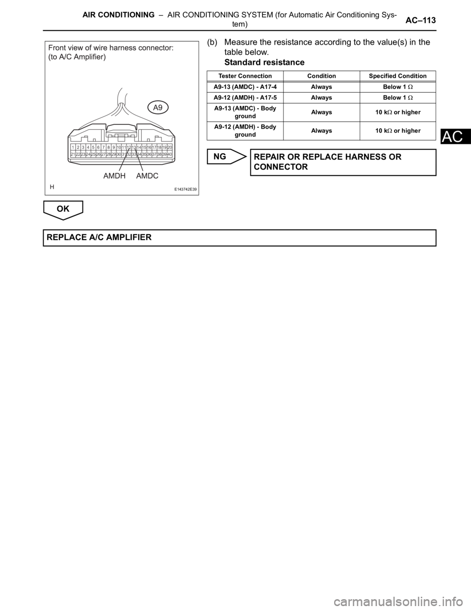
(b) Measure the resistance according to the value(s) in the
table below.
Standard resistance
NG
OK
E143742E39
Tester Connection Condition Specified Condition
A9-13 (AMDC) - A17-4 Always Below 1
A9-12 (AMDH) - A17-5 Always Below 1
A9-13 (AMDC) - Body
groundAlways 10 k or higher
A9-12 (AMDH) - Body
groundAlways 10 k
or higher
REPAIR OR REPLACE HARNESS OR
CONNECTOR
REPLACE A/C AMPLIFIER
Page 2857 of 3000
AC–114AIR CONDITIONING – AIR CONDITIONING SYSTEM (for Automatic Air Conditioning Sys-
tem)
AC
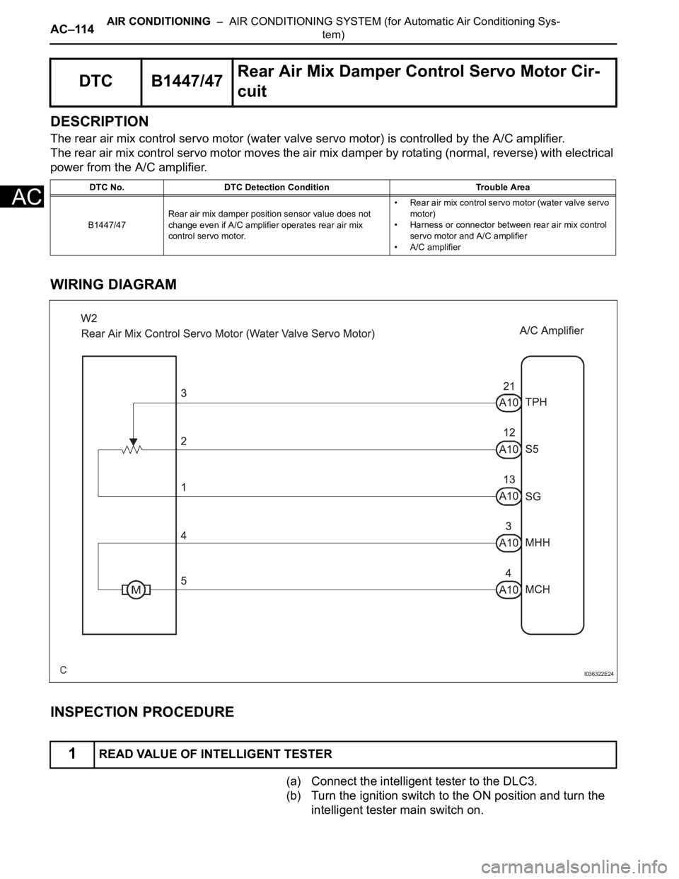
DESCRIPTION
The rear air mix control servo motor (water valve servo motor) is controlled by the A/C amplifier.
The rear air mix control servo motor moves the air mix damper by rotating (normal, reverse) with electrical
power from the A/C amplifier.
WIRING DIAGRAM
INSPECTION PROCEDURE
(a) Connect the intelligent tester to the DLC3.
(b) Turn the ignition switch to the ON position and turn the
intelligent tester main switch on.
DTC B1447/47Rear Air Mix Damper Control Servo Motor Cir-
cuit
DTC No. DTC Detection Condition Trouble Area
B1447/47Rear air mix damper position sensor value does not
change even if A/C amplifier operates rear air mix
control servo motor.• Rear air mix control servo motor (water valve servo
motor)
• Harness or connector between rear air mix control
servo motor and A/C amplifier
• A/C amplifier
1READ VALUE OF INTELLIGENT TESTER
I036322E24
Page 2858 of 3000
AIR CONDITIONING – AIR CONDITIONING SYSTEM (for Automatic Air Conditioning Sys-
tem)AC–115
AC
(c) Select the items in the DATA LIST, and read the display
on the intelligent tester.
DATA LIST / AIR CONDITIONER
OK:
When the target position is "MAX. COOL" (0%), the
actual opening angle is 19.0% or less.
When the target position is "MAX. HOT" (86.5%),
the actual opening angle is 81.0% or more.
Result
B
C
A
(a) Connect the intelligent tester to the DLC3.
(b) Turn the ignition switch to the ON position and turn the
intelligent tester main switch on.
(c) Select the item below in the ACTIVE TEST and then
check the air flow temperature by hand.
ACTIVE TEST / AIR CONDITIONER
OK:
When the lever is moved to the "MAX. HOT" side,
warm air comes out.
When the lever is moved to the "MAX. COOL" side,
cool air comes out.
Result
B
C
Tester Display Measurement Item/Range Normal Condition Diagnostic Note
A/M DAMP POS-RAir mix damper position (Rear) /
min.: -14%, max.: 113.5%
Damper is at "MAX. COOL": 0%
Damper is at "MAX. HOT": 86.5%-
A/M DAMP TARG-RAir mix damper target position
(Rear) / min.: -14%, max.: 113.5%
Result Proceed to
NGA
OK (When troubleshooting according to the PROBLEM SYMPTOMS TABLE) B
OK (When troubleshooting according to the DTC) C
PROCEED TO NEXT CIRCUIT INSPECTION
SHOWN IN PROBLEM SYMPTOMS TABLE
REPLACE A/C AMPLIFIER
2PERFORM ACTIVE TEST BY INTELLIGENT TESTER
Tester Display Test Part Control Range Diagnostic Note
AIR MIX DAMP-R Air mix damper (Rear) min.: -14%, max.: 113.5% -
Result Proceed to
NGA
OK (When troubleshooting according to the PROBLEM SYMPTOMS TABLE) B
OK (When troubleshooting according to the DTC) C
PROCEED TO NEXT CIRCUIT INSPECTION
SHOWN IN PROBLEM SYMPTOMS TABLE
REPLACE A/C AMPLIFIER
Page 2859 of 3000
AC–116AIR CONDITIONING – AIR CONDITIONING SYSTEM (for Automatic Air Conditioning Sys-
tem)
AC
A
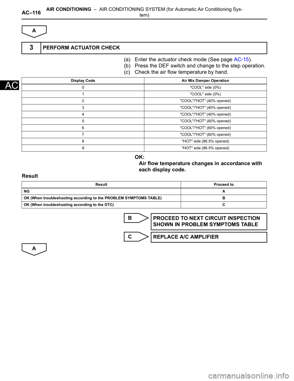
(a) Enter the actuator check mode (See page AC-15).
(b) Press the DEF switch and change to the step operation.
(c) Check the air flow temperature by hand.
OK:
Air flow temperature changes in accordance with
each display code.
Result
B
C
A
3PERFORM ACTUATOR CHECK
Display Code Air Mix Damper Operation
0 "COOL" side (0%)
1 "COOL" side (0%)
2 "COOL"/"HOT" (40% opened)
3 "COOL"/"HOT" (40% opened)
4 "COOL"/"HOT" (40% opened)
5 "COOL"/"HOT" (60% opened)
6 "COOL"/"HOT" (60% opened)
7 "COOL"/"HOT" (60% opened)
8 "HOT" side (86.5% opened)
9 "HOT" side (86.5% opened)
Result Proceed to
NGA
OK (When troubleshooting according to the PROBLEM SYMPTOMS TABLE) B
OK (When troubleshooting according to the DTC) C
PROCEED TO NEXT CIRCUIT INSPECTION
SHOWN IN PROBLEM SYMPTOMS TABLE
REPLACE A/C AMPLIFIER
Page 2860 of 3000
AIR CONDITIONING – AIR CONDITIONING SYSTEM (for Automatic Air Conditioning Sys-
tem)AC–117
AC
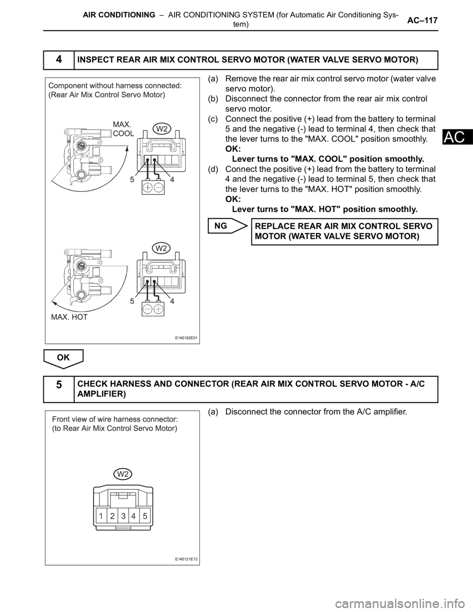
(a) Remove the rear air mix control servo motor (water valve
servo motor).
(b) Disconnect the connector from the rear air mix control
servo motor.
(c) Connect the positive (+) lead from the battery to terminal
5 and the negative (-) lead to terminal 4, then check that
the lever turns to the "MAX. COOL" position smoothly.
OK:
Lever turns to "MAX. COOL" position smoothly.
(d) Connect the positive (+) lead from the battery to terminal
4 and the negative (-) lead to terminal 5, then check that
the lever turns to the "MAX. HOT" position smoothly.
OK:
Lever turns to "MAX. HOT" position smoothly.
NG
OK
(a) Disconnect the connector from the A/C amplifier.
4INSPECT REAR AIR MIX CONTROL SERVO MOTOR (WATER VALVE SERVO MOTOR)
E145192E01
REPLACE REAR AIR MIX CONTROL SERVO
MOTOR (WATER VALVE SERVO MOTOR)
5CHECK HARNESS AND CONNECTOR (REAR AIR MIX CONTROL SERVO MOTOR - A/C
AMPLIFIER)
E145121E13