TOYOTA SIENNA 2007 Service Repair Manual
Manufacturer: TOYOTA, Model Year: 2007, Model line: SIENNA, Model: TOYOTA SIENNA 2007Pages: 3000, PDF Size: 52.26 MB
Page 2881 of 3000
AC–138AIR CONDITIONING – AIR CONDITIONING SYSTEM (for Automatic Air Conditioning Sys-
tem)
AC
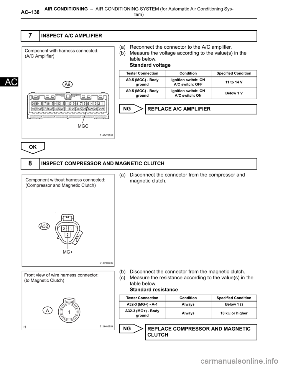
(a) Reconnect the connector to the A/C amplifier.
(b) Measure the voltage according to the value(s) in the
table below.
Standard voltage
NG
OK
(a) Disconnect the connector from the compressor and
magnetic clutch.
(b) Disconnect the connector from the magnetic clutch.
(c) Measure the resistance according to the value(s) in the
table below.
Standard resistance
NG
7INSPECT A/C AMPLIFIER
E147476E02
Tester Connection Condition Specified Condition
A9-5 (MGC) - Body
groundIgnition switch: ON
A/C switch: OFF11 to 14 V
A9-5 (MGC) - Body
groundIgnition switch: ON
A/C switch: ONBelow 1 V
REPLACE A/C AMPLIFIER
8INSPECT COMPRESSOR AND MAGNETIC CLUTCH
E145186E02
E124482E04
Tester Connection Condition Specified Condition
A32-3 (MG+) - A-1 Always Below 1
A32-3 (MG+) - Body
groundAlways 10 k or higher
REPLACE COMPRESSOR AND MAGNETIC
CLUTCH
Page 2882 of 3000
AIR CONDITIONING – AIR CONDITIONING SYSTEM (for Automatic Air Conditioning Sys-
tem)AC–139
AC
OK
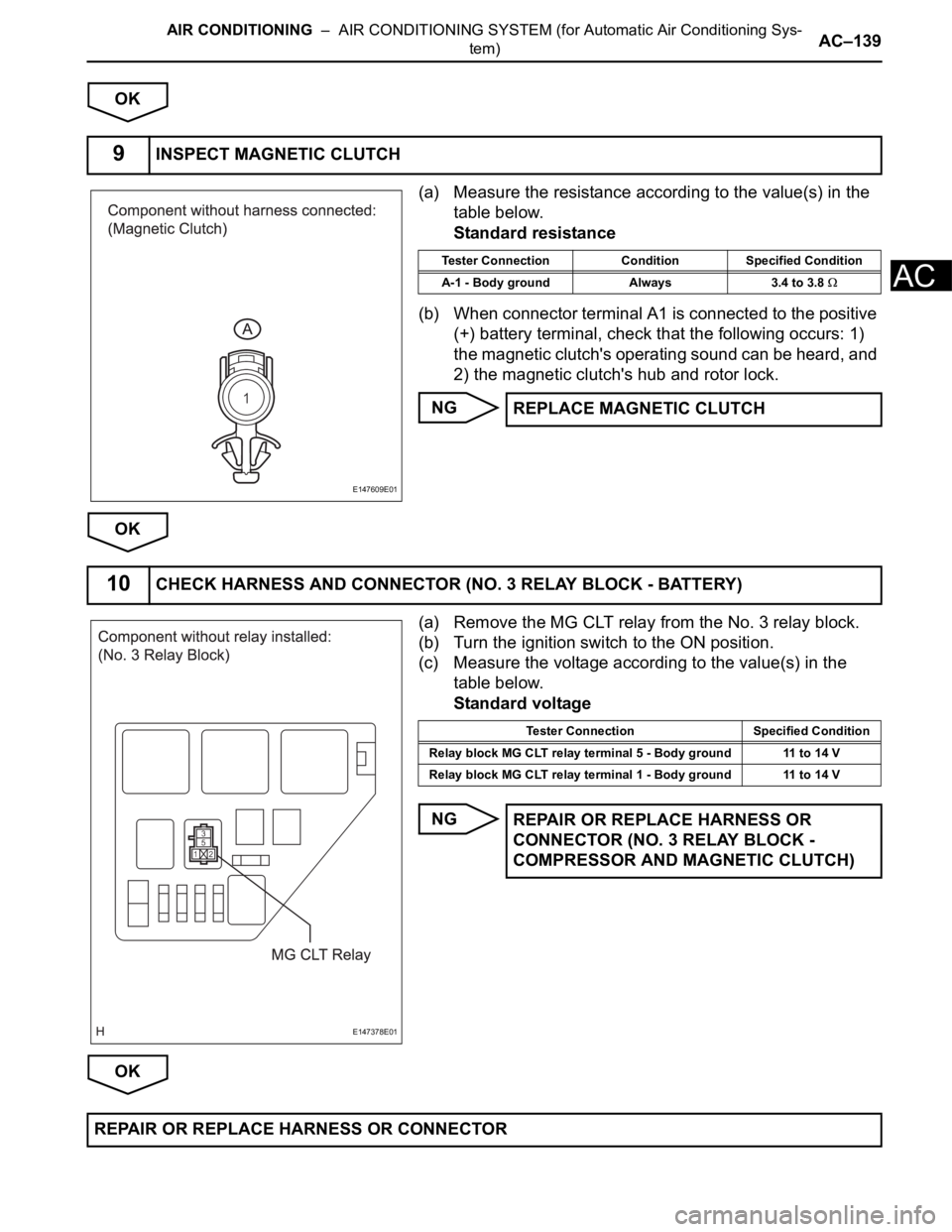
(a) Measure the resistance according to the value(s) in the
table below.
Standard resistance
(b) When connector terminal A1 is connected to the positive
(+) battery terminal, check that the following occurs: 1)
the magnetic clutch's operating sound can be heard, and
2) the magnetic clutch's hub and rotor lock.
NG
OK
(a) Remove the MG CLT relay from the No. 3 relay block.
(b) Turn the ignition switch to the ON position.
(c) Measure the voltage according to the value(s) in the
table below.
Standard voltage
NG
OK
9INSPECT MAGNETIC CLUTCH
E147609E01
Tester Connection Condition Specified Condition
A-1 - Body ground Always 3.4 to 3.8
REPLACE MAGNETIC CLUTCH
10CHECK HARNESS AND CONNECTOR (NO. 3 RELAY BLOCK - BATTERY)
E147378E01
Tester Connection Specified Condition
Relay block MG CLT relay terminal 5 - Body ground 11 to 14 V
Relay block MG CLT relay terminal 1 - Body ground 11 to 14 V
REPAIR OR REPLACE HARNESS OR
CONNECTOR (NO. 3 RELAY BLOCK -
COMPRESSOR AND MAGNETIC CLUTCH)
REPAIR OR REPLACE HARNESS OR CONNECTOR
Page 2883 of 3000
AC–140AIR CONDITIONING – AIR CONDITIONING SYSTEM (for Automatic Air Conditioning Sys-
tem)
AC
DESCRIPTION
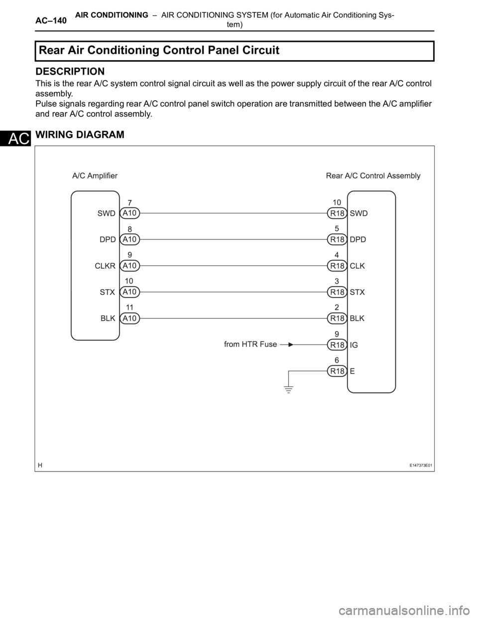
This is the rear A/C system control signal circuit as well as the power supply circuit of the rear A/C control
assembly.
Pulse signals regarding rear A/C control panel switch operation are transmitted between the A/C amplifier
and rear A/C control assembly.
WIRING DIAGRAM
Rear Air Conditioning Control Panel Circuit
E147373E01
Page 2884 of 3000
AIR CONDITIONING – AIR CONDITIONING SYSTEM (for Automatic Air Conditioning Sys-
tem)AC–141
AC
INSPECTION PROCEDURE
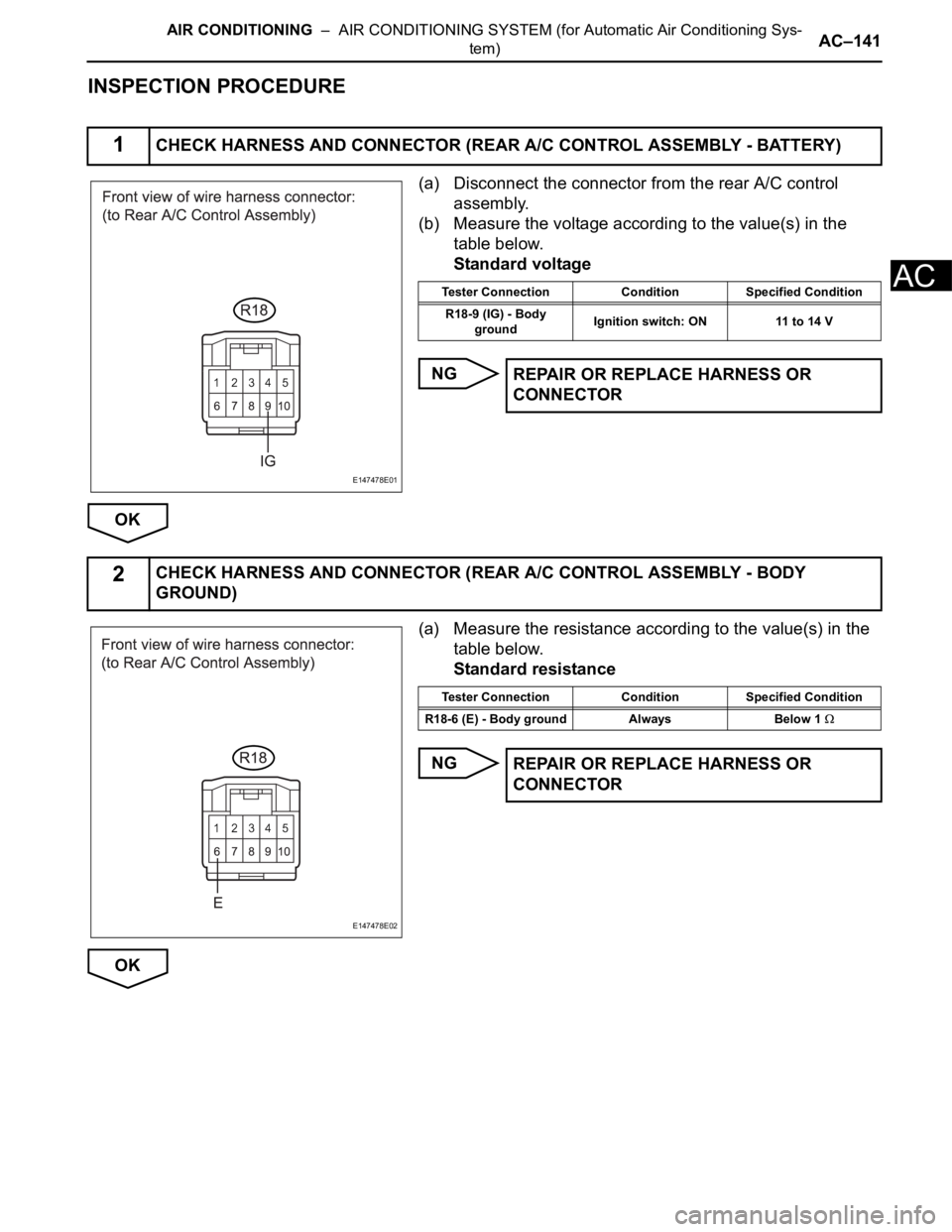
(a) Disconnect the connector from the rear A/C control
assembly.
(b) Measure the voltage according to the value(s) in the
table below.
Standard voltage
NG
OK
(a) Measure the resistance according to the value(s) in the
table below.
Standard resistance
NG
OK
1CHECK HARNESS AND CONNECTOR (REAR A/C CONTROL ASSEMBLY - BATTERY)
E147478E01
Tester Connection Condition Specified Condition
R18-9 (IG) - Body
groundIgnition switch: ON 11 to 14 V
REPAIR OR REPLACE HARNESS OR
CONNECTOR
2CHECK HARNESS AND CONNECTOR (REAR A/C CONTROL ASSEMBLY - BODY
GROUND)
E147478E02
Tester Connection Condition Specified Condition
R18-6 (E) - Body ground Always Below 1
REPAIR OR REPLACE HARNESS OR
CONNECTOR
Page 2885 of 3000
AC–142AIR CONDITIONING – AIR CONDITIONING SYSTEM (for Automatic Air Conditioning Sys-
tem)
AC
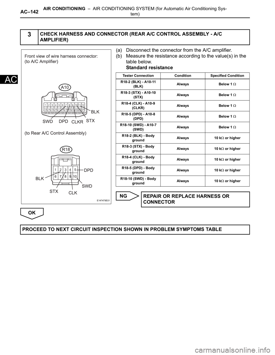
(a) Disconnect the connector from the A/C amplifier.
(b) Measure the resistance according to the value(s) in the
table below.
Standard resistance
NG
OK
3CHECK HARNESS AND CONNECTOR (REAR A/C CONTROL ASSEMBLY - A/C
AMPLIFIER)
E147479E01
Tester Connection Condition Specified Condition
R18-2 (BLK) - A10-11
(BLK)Always Below 1
R18-3 (STX) - A10-10
(STX)Always Below 1
R18-4 (CLK) - A10-9
(CLKR)Always Below 1
R18-5 (DPD) - A10-8
(DPD)Always Below 1
R18-10 (SWD) - A10-7
(SWD)Always Below 1
R18-2 (BLK) - Body
groundAlways 10 k or higher
R18-3 (STX) - Body
groundAlways 10 k
or higher
R18-4 (CLK) - Body
groundAlways 10 k
or higher
R18-5 (DPD) - Body
groundAlways 10 k
or higher
R18-10 (SWD) - Body
groundAlways 10 k
or higher
REPAIR OR REPLACE HARNESS OR
CONNECTOR
PROCEED TO NEXT CIRCUIT INSPECTION SHOWN IN PROBLEM SYMPTOMS TABLE
Page 2886 of 3000
AIR CONDITIONING – AIR CONDITIONING SYSTEM (for Automatic Air Conditioning Sys-
tem)AC–143
AC
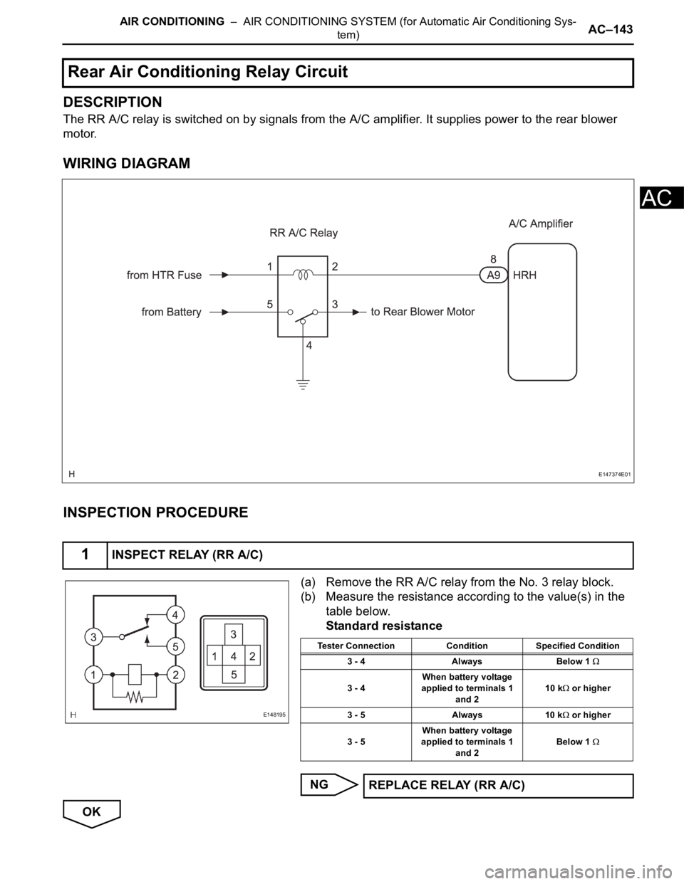
DESCRIPTION
The RR A/C relay is switched on by signals from the A/C amplifier. It supplies power to the rear blower
motor.
WIRING DIAGRAM
INSPECTION PROCEDURE
(a) Remove the RR A/C relay from the No. 3 relay block.
(b) Measure the resistance according to the value(s) in the
table below.
Standard resistance
NG
OK
Rear Air Conditioning Relay Circuit
1INSPECT RELAY (RR A/C)
E147374E01
E148195
Tester Connection Condition Specified Condition
3 - 4 Always Below 1
3 - 4When battery voltage
applied to terminals 1
and 210 k or higher
3 - 5 Always 10 k
or higher
3 - 5When battery voltage
applied to terminals 1
and 2Below 1
REPLACE RELAY (RR A/C)
Page 2887 of 3000
AC–144AIR CONDITIONING – AIR CONDITIONING SYSTEM (for Automatic Air Conditioning Sys-
tem)
AC
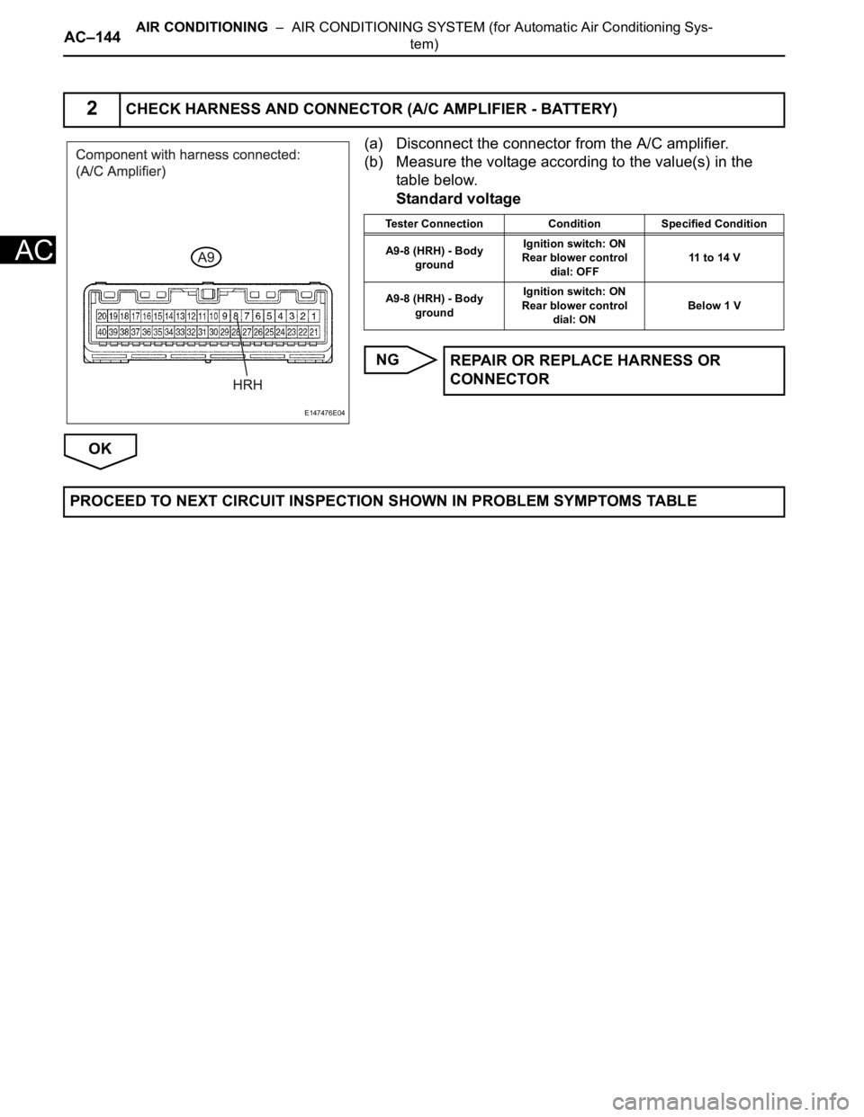
(a) Disconnect the connector from the A/C amplifier.
(b) Measure the voltage according to the value(s) in the
table below.
Standard voltage
NG
OK
2CHECK HARNESS AND CONNECTOR (A/C AMPLIFIER - BATTERY)
E147476E04
Tester Connection Condition Specified Condition
A9-8 (HRH) - Body
groundIgnition switch: ON
Rear blower control
dial: OFF11 to 14 V
A9-8 (HRH) - Body
groundIgnition switch: ON
Rear blower control
dial: ONBelow 1 V
REPAIR OR REPLACE HARNESS OR
CONNECTOR
PROCEED TO NEXT CIRCUIT INSPECTION SHOWN IN PROBLEM SYMPTOMS TABLE
Page 2888 of 3000
AIR CONDITIONING – AIR CONDITIONING SYSTEM (for Automatic Air Conditioning Sys-
tem)AC–145
AC
DESCRIPTION
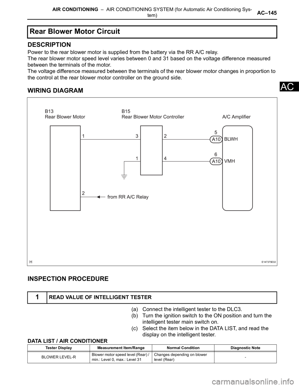
Power to the rear blower motor is supplied from the battery via the RR A/C relay.
The rear blower motor speed level varies between 0 and 31 based on the voltage difference measured
between the terminals of the motor.
The voltage difference measured between the terminals of the rear blower motor changes in proportion to
the control at the rear blower motor controller on the ground side.
WIRING DIAGRAM
INSPECTION PROCEDURE
(a) Connect the intelligent tester to the DLC3.
(b) Turn the ignition switch to the ON position and turn the
intelligent tester main switch on.
(c) Select the item below in the DATA LIST, and read the
display on the intelligent tester.
DATA LIST / AIR CONDITIONER
Rear Blower Motor Circuit
1READ VALUE OF INTELLIGENT TESTER
E147375E02
Tester Display Measurement Item/Range Normal Condition Diagnostic Note
BLOWER LEVEL-RBlower motor speed level (Rear) /
min.: Level 0, max.: Level 31Changes depending on blower
level (Rear)-
Page 2889 of 3000
AC–146AIR CONDITIONING – AIR CONDITIONING SYSTEM (for Automatic Air Conditioning Sys-
tem)
AC
OK:
The display is as specified in the normal condition.
NG
OK
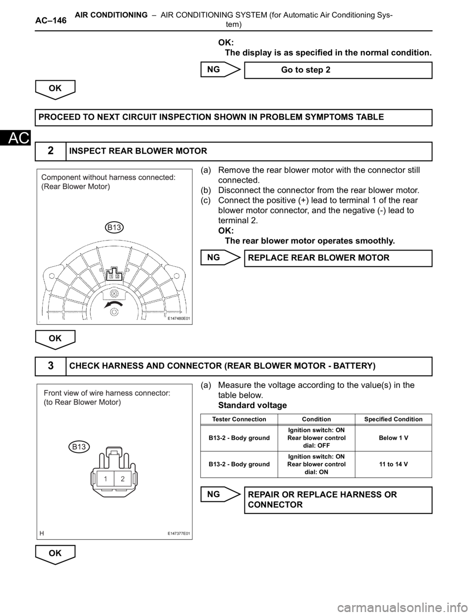
(a) Remove the rear blower motor with the connector still
connected.
(b) Disconnect the connector from the rear blower motor.
(c) Connect the positive (+) lead to terminal 1 of the rear
blower motor connector, and the negative (-) lead to
terminal 2.
OK:
The rear blower motor operates smoothly.
NG
OK
(a) Measure the voltage according to the value(s) in the
table below.
Standard voltage
NG
OK Go to step 2
PROCEED TO NEXT CIRCUIT INSPECTION SHOWN IN PROBLEM SYMPTOMS TABLE
2INSPECT REAR BLOWER MOTOR
E147480E01
REPLACE REAR BLOWER MOTOR
3CHECK HARNESS AND CONNECTOR (REAR BLOWER MOTOR - BATTERY)
E147377E01
Tester Connection Condition Specified Condition
B13-2 - Body groundIgnition switch: ON
Rear blower control
dial: OFFBelow 1 V
B13-2 - Body groundIgnition switch: ON
Rear blower control
dial: ON11 to 14 V
REPAIR OR REPLACE HARNESS OR
CONNECTOR
Page 2890 of 3000
AIR CONDITIONING – AIR CONDITIONING SYSTEM (for Automatic Air Conditioning Sys-
tem)AC–147
AC
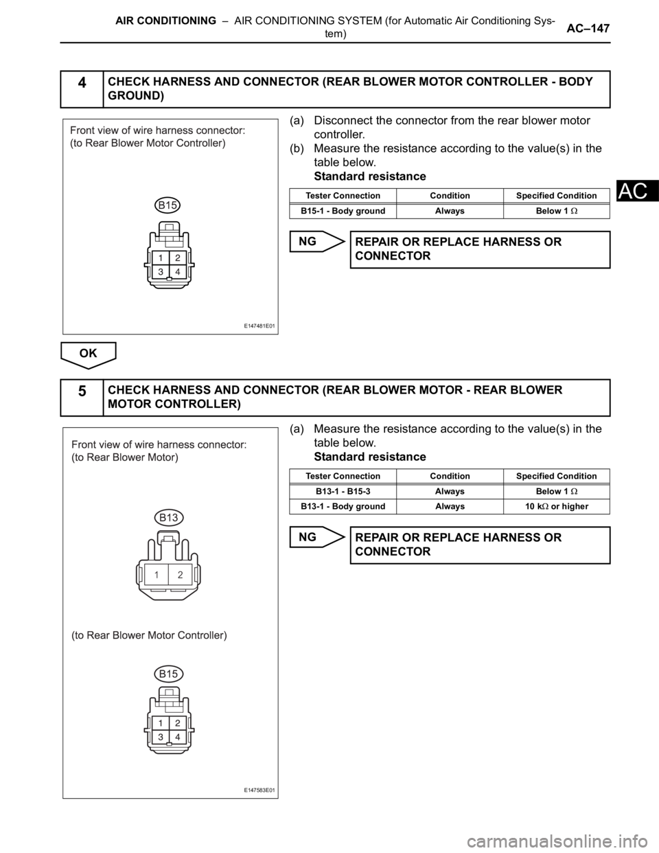
(a) Disconnect the connector from the rear blower motor
controller.
(b) Measure the resistance according to the value(s) in the
table below.
Standard resistance
NG
OK
(a) Measure the resistance according to the value(s) in the
table below.
Standard resistance
NG
4CHECK HARNESS AND CONNECTOR (REAR BLOWER MOTOR CONTROLLER - BODY
GROUND)
E147481E01
Tester Connection Condition Specified Condition
B15-1 - Body ground Always Below 1
REPAIR OR REPLACE HARNESS OR
CONNECTOR
5CHECK HARNESS AND CONNECTOR (REAR BLOWER MOTOR - REAR BLOWER
MOTOR CONTROLLER)
E147583E01
Tester Connection Condition Specified Condition
B13-1 - B15-3 Always Below 1
B13-1 - Body ground Always 10 k or higher
REPAIR OR REPLACE HARNESS OR
CONNECTOR