brake TOYOTA SIENNA 2007 Service Owner's Manual
[x] Cancel search | Manufacturer: TOYOTA, Model Year: 2007, Model line: SIENNA, Model: TOYOTA SIENNA 2007Pages: 3000, PDF Size: 52.26 MB
Page 186 of 3000
BR–12BRAKE – BRAKE PEDAL
BR
DISASSEMBLY
1. REMOVE STOP LIGHT SWITCH ASSEMBLY
(a) Turn the stop light switch assembly
counterclockwise and remove the stop light switch
assembly.
(b) Remove the stop light switch mounting adjuster
from the brake pedal support sub-assembly.
2. REMOVE STOP LIGHT SWITCH CUSHION
(a) Remove the stop light switch cushion from the brake
pedal sub-assembly.
3. REMOVE BRAKE PEDAL
(a) Remove the 2 brake pedal shafts, 2 nuts and brake
pedal from the brake pedal support sub-assembly.
4. REMOVE BRAKE PEDAL BUSH
(a) Remove the 4 brake pedal bushes from the brake
pedal.
5. REMOVE BRAKE PEDAL SHAFT COLLAR
(a) Remove the 2 brake pedal shaft collars from the
brake pedal.
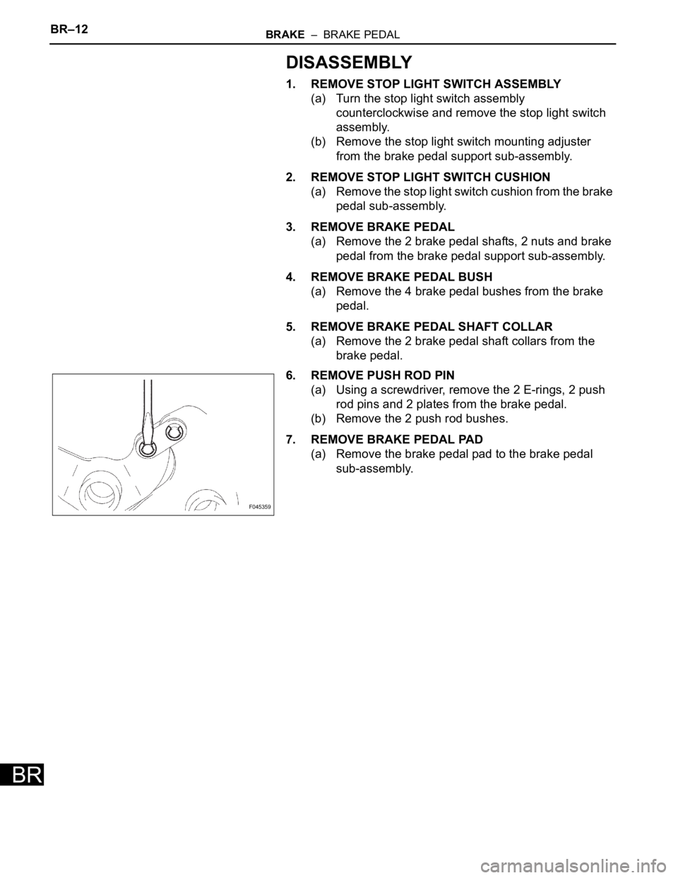
6. REMOVE PUSH ROD PIN
(a) Using a screwdriver, remove the 2 E-rings, 2 push
rod pins and 2 plates from the brake pedal.
(b) Remove the 2 push rod bushes.
7. REMOVE BRAKE PEDAL PAD
(a) Remove the brake pedal pad to the brake pedal
sub-assembly.
F045359
Page 187 of 3000
PARKING BRAKE – PARKING BRAKE PEDALPB–5
PB
REMOVAL
1. DISCONNECT BATTERY NEGATIVE TERMINAL
2. REMOVE FRONT DOOR SCUFF PLATE LH
3. REMOVE COWL SIDE TRIM BOARD LH
4. REMOVE INSTRUMENT PANEL FINISH PANEL SUB-
ASSEMBLY LOWER LH (See page IP-6)
5. REMOVE REAR DOOR SCUFF PLATE RH
6. REMOVE REAR DOOR SCUFF PLATE LH
7. REMOVE FRONT SEAT ASSEMBLY LH
HINT:
• Manual Seat Type (See page SE-48)
• Power Seat Type (See page SE-58)
• Fold Flat Type (See page SE-40)
8. REMOVE REAR SEAT NO.1 ASSEMBLY
HINT:
• Captain Seat Type (See page SE-68)
• Center Seat Type (See page SE-77)
9. REMOVE REAR FLOOR SEAT LOCK COVER
10. REMOVE REAR FLOOR SEAT LOCK COVER
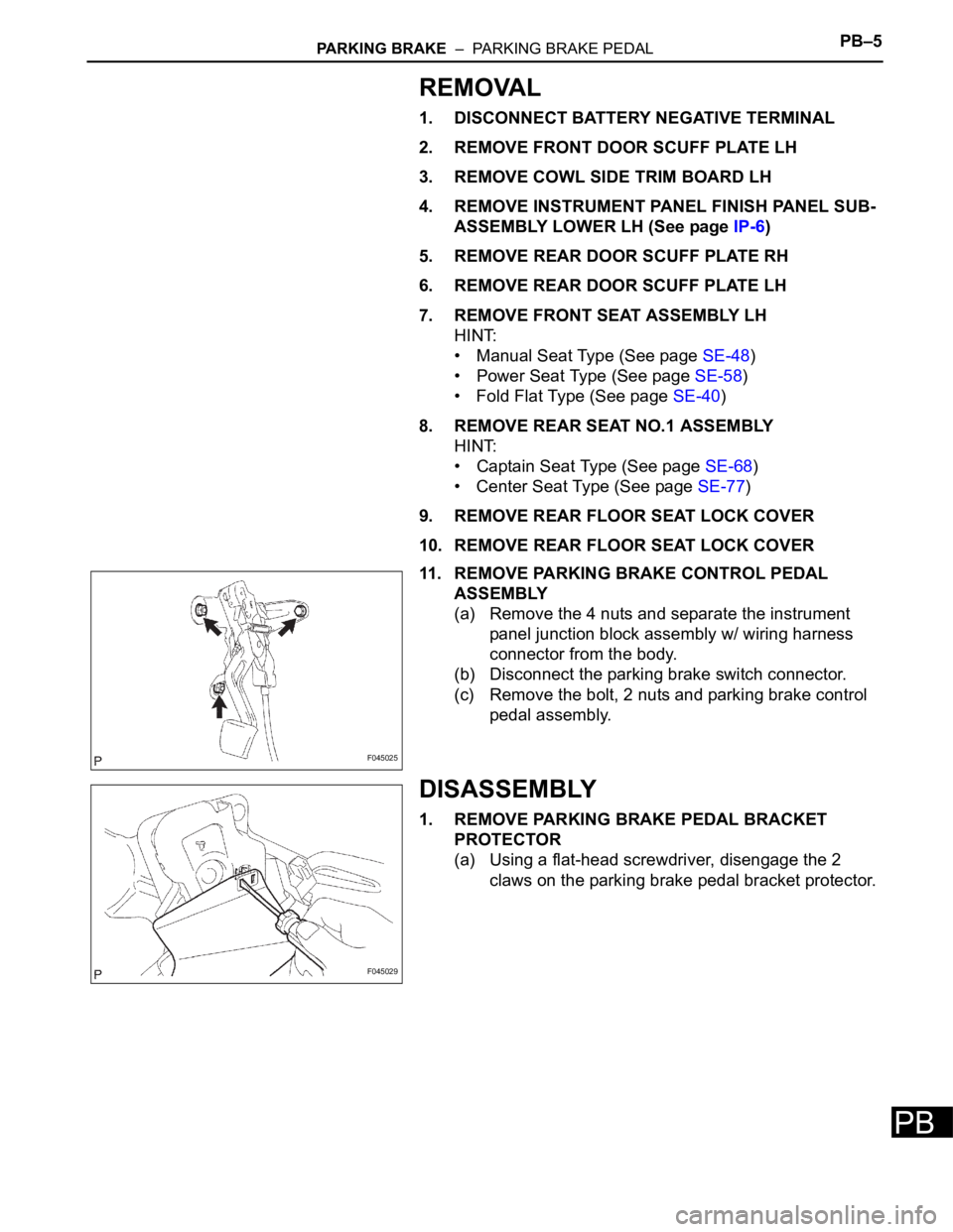
11. REMOVE PARKING BRAKE CONTROL PEDAL
ASSEMBLY
(a) Remove the 4 nuts and separate the instrument
panel junction block assembly w/ wiring harness
connector from the body.
(b) Disconnect the parking brake switch connector.
(c) Remove the bolt, 2 nuts and parking brake control
pedal assembly.
DISASSEMBLY
1. REMOVE PARKING BRAKE PEDAL BRACKET
PROTECTOR
(a) Using a flat-head screwdriver, disengage the 2
claws on the parking brake pedal bracket protector.
F045025
F045029
Page 188 of 3000
PB–6PARKING BRAKE – PARKING BRAKE PEDAL
PB
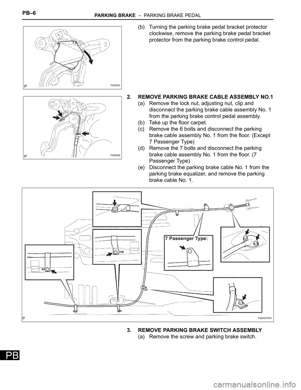
(b) Turning the parking brake pedal bracket protector
clockwise, remove the parking brake pedal bracket
protector from the parking brake control pedal.
2. REMOVE PARKING BRAKE CABLE ASSEMBLY NO.1
(a) Remove the lock nut, adjusting nut, clip and
disconnect the parking brake cable assembly No. 1
from the parking brake control pedal assembly.
(b) Take up the floor carpet.
(c) Remove the 6 bolts and disconnect the parking
brake cable assembly No. 1 from the floor. (Except
7 Passenger Type)
(d) Remove the 7 bolts and disconnect the parking
brake cable assembly No. 1 from the floor. (7
Passenger Type)
(e) Disconnect the parking brake cable No. 1 from the
parking brake equalizer, and remove the parking
brake cable No. 1.
3. REMOVE PARKING BRAKE SWITCH ASSEMBLY
(a) Remove the screw and parking brake switch.
F045030
F045026
F045027E01
Page 214 of 3000
SERVICE SPECIFICATIONS – U151F AUTOMATIC TRANSAXLESS–37
SS
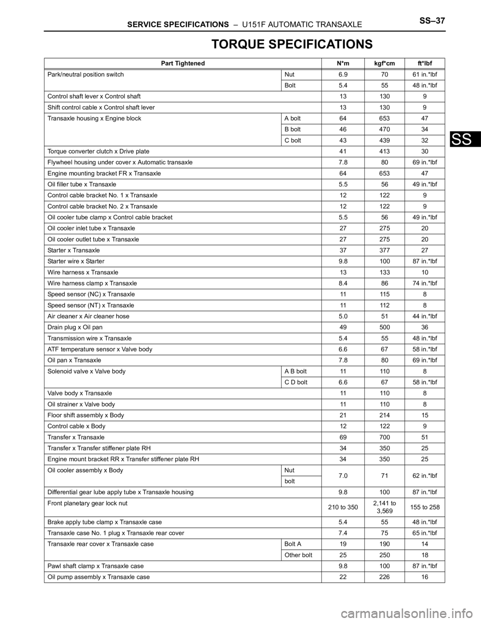
TORQUE SPECIFICATIONS
Part Tightened N*m kgf*cm ft*lbf
Park/neutral position switch Nut 6.9 70 61 in.*lbf
Bolt 5.4 55 48 in.*lbf
Control shaft lever x Control shaft 13 130 9
Shift control cable x Control shaft lever 13 130 9
Transaxle housing x Engine block A bolt 64 653 47
B bolt 46 470 34
C bolt 43 439 32
Torque converter clutch x Drive plate 41 413 30
Flywheel housing under cover x Automatic transaxle 7.8 80 69 in.*lbf
Engine mounting bracket FR x Transaxle 64 653 47
Oil filler tube x Transaxle5.5 56 49 in.*lbf
Control cable bracket No. 1 x Transaxle 12 122 9
Control cable bracket No. 2 x Transaxle 12 122 9
Oil cooler tube clamp x Control cable bracket 5.5 56 49 in.*lbf
Oil cooler inlet tube x Transaxle27 275 20
Oil cooler outlet tube x Transaxle 27 275 20
Starter x Transaxle37 377 27
Starter wire x Starter9.8 100 87 in.*lbf
Wire harness x Transaxle13 133 10
Wire harness clamp x Transaxle8.4 86 74 in.*lbf
Speed sensor (NC) x Transaxle11 11 5 8
Speed sensor (NT) x Transaxle11 11 2 8
Air cleaner x Air cleaner hose5.0 51 44 in.*lbf
Drain plug x Oil pan49 500 36
Transmission wire x Transaxle5.4 55 48 in.*lbf
ATF temperature sensor x Valve body 6.6 67 58 in.*lbf
Oil pan x Transaxle7.8 80 69 in.*lbf
Solenoid valve x Valve body A B bolt 11 110 8
C D bolt 6.6 67 58 in.*lbf
Valve body x Transaxle11 11 0 8
Oil strainer x Valve body11 11 0 8
Floor shift assembly x Body21 214 15
Control cable x Body12 122 9
Transfer x Transaxle69 700 51
Transfer x Transfer stiffener plate RH 34 350 25
Engine mount bracket RR x Transfer stiffener plate RH 34 350 25
Oil cooler assembly x Body Nut
7.0 71 62 in.*lbf
bolt
Differential gear lube apply tube x Transaxle housing 9.8 100 87 in.*lbf
Front planetary gear lock nut
210 to 3502,141 to
3,569155 to 258
Brake apply tube clamp x Transaxle case 5.4 55 48 in.*lbf
Transaxle case No. 1 plug x Transaxle rear cover 7.4 75 65 in.*lbf
Transaxle rear cover x Transaxle case Bolt A 19 190 14
Other bolt 25 250 18
Pawl shaft clamp x Transaxle case 9.8 100 87 in.*lbf
Oil pump assembly x Transaxle case 22 226 16
Page 221 of 3000

SERVICE SPECIFICATIONS – U151E AUTOMATIC TRANSAXLESS–27
SS
Direct clutch & O/D clutch
Pack clearance0.61 to 0.83 mm (0.02401 to 0.03268 in.)
Return spring free length25.91 mm (1.0201 in.)
Flange thickness Mark
0 2.5 mm (0.098 in.)
1 2.6 mm (0.102 in.)
2 2.7 mm (0.106 in.)
3 2.8 mm (0.110 in.)
4 2.9 mm (0.114 in.)
5 3.0 mm (0.118 in.)
6 3.1 mm (0.122 in.)
2nd brake
Pack clearance0.62 to 0.91 mm (0.0244 to 0.0358 in.)
Return spring free length16.61 mm (0.6539 in.)
Flange thickness Mark
1 3.0 mm (0.118 in.)
2 3.1 mm (0.122 in.)
3 3.2 mm (0.126 in.)
4 3.3 mm (0.130 in.)
5 3.4 mm (0.134 in.)
6 3.5 mm (0.138 in.)
7 3.6 mm (0.142 in.)
U/D clutch
Pack clearance1.51 to 1.71 mm (0.0594 to 0.0673 in.)
U/D clutch drum bushing inside diameter STD 37.06 to 37.08 mm (1.4591 to 1.4598 in.)
Max. 37.13 mm (1.4618 in.)
Return spring free length17.14 mm (0.6752 in.)
Flange thickness Mark
1 3.0 mm (0.118 in.)
2 3.1 mm (0.122 in.)
3 3.2 mm (0.126 in.)
4 3.3 mm (0.130 in.)
5 3.4 mm (0.134 in.)
U/D brake
Pack clearance1.81 to 2.20 mm (0.0713 to 0.0866 in.)
Return spring free length14.04 mm (0.5528 in.)
Flange thickness Mark
1 3.0 mm (0.118 in.)
2 3.2 mm (0.126 in.)
3 3.4 mm (0.134 in.)
1st & reverse brake
Pack clearance1.16 to 1.35 mm (0.0457 to 0.0531in.)
Return spring free length15.53 mm (0.6114 in.)
Page 222 of 3000
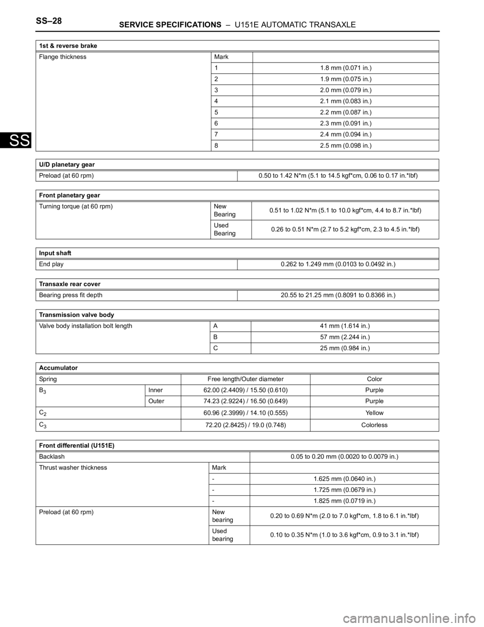
SS–28SERVICE SPECIFICATIONS – U151E AUTOMATIC TRANSAXLE
SS
Flange thickness Mark
1 1.8 mm (0.071 in.)
2 1.9 mm (0.075 in.)
3 2.0 mm (0.079 in.)
4 2.1 mm (0.083 in.)
5 2.2 mm (0.087 in.)
6 2.3 mm (0.091 in.)
7 2.4 mm (0.094 in.)
8 2.5 mm (0.098 in.)
U/D planetary gear
Preload (at 60 rpm) 0.50 to 1.42 N*m (5.1 to 14.5 kgf*cm, 0.06 to 0.17 in.*lbf)
Front planetary gear
Turning torque (at 60 rpm) New
Bearing0.51 to 1.02 N*m (5.1 to 10.0 kgf*cm, 4.4 to 8.7 in.*lbf)
Used
Bearing0.26 to 0.51 N*m (2.7 to 5.2 kgf*cm, 2.3 to 4.5 in.*lbf)
Input shaft
End play0.262 to 1.249 mm (0.0103 to 0.0492 in.)
Transaxle rear cover
Bearing press fit depth 20.55 to 21.25 mm (0.8091 to 0.8366 in.)
Transmission valve body
Valve body installation bolt length A 41 mm (1.614 in.)
B 57 mm (2.244 in.)
C 25 mm (0.984 in.)
Accumulator
Spring Free length/Outer diameter Color
B
3Inner 62.00 (2.4409) / 15.50 (0.610) Purple
Outer 74.23 (2.9224) / 16.50 (0.649) Purple
C
260.96 (2.3999) / 14.10 (0.555) Yellow
C
372.20 (2.8425) / 19.0 (0.748) Colorless
Front differential (U151E)
Backlash0.05 to 0.20 mm (0.0020 to 0.0079 in.)
Thrust washer thickness Mark
- 1.625 mm (0.0640 in.)
- 1.725 mm (0.0679 in.)
- 1.825 mm (0.0719 in.)
Preload (at 60 rpm) New
bearing0.20 to 0.69 N*m (2.0 to 7.0 kgf*cm, 1.8 to 6.1 in.*lbf)
Used
bearing0.10 to 0.35 N*m (1.0 to 3.6 kgf*cm, 0.9 to 3.1 in.*lbf) 1st & reverse brake
Page 226 of 3000
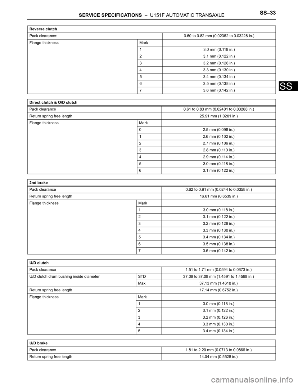
SERVICE SPECIFICATIONS – U151F AUTOMATIC TRANSAXLESS–33
SS
Reverse clutch
Pack clearance:0.60 to 0.82 mm (0.02362 to 0.03228 in.)
Flange thickness Mark
1 3.0 mm (0.118 in.)
2 3.1 mm (0.122 in.)
3 3.2 mm (0.126 in.)
4 3.3 mm (0.130 in.)
5 3.4 mm (0.134 in.)
6 3.5 mm (0.138 in.)
7 3.6 mm (0.142 in.)
Direct clutch & O/D clutch
Pack clearance0.61 to 0.83 mm (0.02401 to 0.03268 in.)
Return spring free length25.91 mm (1.0201 in.)
Flange thickness Mark
0 2.5 mm (0.098 in.)
1 2.6 mm (0.102 in.)
2 2.7 mm (0.106 in.)
3 2.8 mm (0.110 in.)
4 2.9 mm (0.114 in.)
5 3.0 mm (0.118 in.)
6 3.1 mm (0.122 in.)
2nd brake
Pack clearance0.62 to 0.91 mm (0.0244 to 0.0358 in.)
Return spring free length16.61 mm (0.6539 in.)
Flange thickness Mark
1 3.0 mm (0.118 in.)
2 3.1 mm (0.122 in.)
3 3.2 mm (0.126 in.)
4 3.3 mm (0.130 in.)
5 3.4 mm (0.134 in.)
6 3.5 mm (0.138 in.)
7 3.6 mm (0.142 in.)
U/D clutch
Pack clearance1.51 to 1.71 mm (0.0594 to 0.0673 in.)
U/D clutch drum bushing inside diameter STD 37.06 to 37.08 mm (1.4591 to 1.4598 in.)
Max. 37.13 mm (1.4618 in.)
Return spring free length17.14 mm (0.6752 in.)
Flange thickness Mark
1 3.0 mm (0.118 in.)
2 3.1 mm (0.122 in.)
3 3.2 mm (0.126 in.)
4 3.3 mm (0.130 in.)
5 3.4 mm (0.134 in.)
U/D brake
Pack clearance1.81 to 2.20 mm (0.0713 to 0.0866 in.)
Return spring free length14.04 mm (0.5528 in.)
Page 227 of 3000
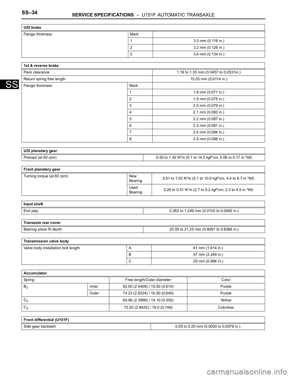
SS–34SERVICE SPECIFICATIONS – U151F AUTOMATIC TRANSAXLE
SS
Flange thickness Mark
1 3.0 mm (0.118 in.)
2 3.2 mm (0.126 in.)
3 3.4 mm (0.134 in.)
1st & reverse brake
Pack clearance1.16 to 1.35 mm (0.0457 to 0.0531in.)
Return spring free length15.53 mm (0.6114 in.)
Flange thickness Mark
1 1.8 mm (0.071 in.)
2 1.9 mm (0.075 in.)
3 2.0 mm (0.079 in.)
4 2.1 mm (0.083 in.)
5 2.2 mm (0.087 in.)
6 2.3 mm (0.091 in.)
7 2.4 mm (0.094 in.)
8 2.5 mm (0.098 in.)
U/D planetary gear
Preload (at 60 rpm) 0.50 to 1.42 N*m (5.1 to 14.5 kgf*cm, 0.06 to 0.17 in.*lbf)
Front planetary gear
Turning torque (at 60 rpm) New
Bearing0.51 to 1.02 N*m (5.1 to 10.0 kgf*cm, 4.4 to 8.7 in.*lbf)
Used
Bearing0.26 to 0.51 N*m (2.7 to 5.2 kgf*cm, 2.3 to 4.5 in.*lbf)
Input shaft
End play0.262 to 1.249 mm (0.0103 to 0.0492 in.)
Transaxle rear cover
Bearing press fit depth 20.55 to 21.25 mm (0.8091 to 0.8366 in.)
Transmission valve body
Valve body installation bolt length A 41 mm (1.614 in.)
B 57 mm (2.244 in.)
C 25 mm (0.984 in.)
Accumulator
Spring Free length/Outer diameter Color
B
3Inner 62.00 (2.4409) / 15.50 (0.610) Purple
Outer 74.23 (2.9224) / 16.50 (0.649) Purple
C
260.96 (2.3999) / 14.10 (0.555) Yellow
C
372.20 (2.8425) / 19.0 (0.748) Colorless
Front differential (U151F)
Side gear backlash 0.05 to 0.20 mm (0.0020 to 0.0079 in.) U/D brake
Page 354 of 3000
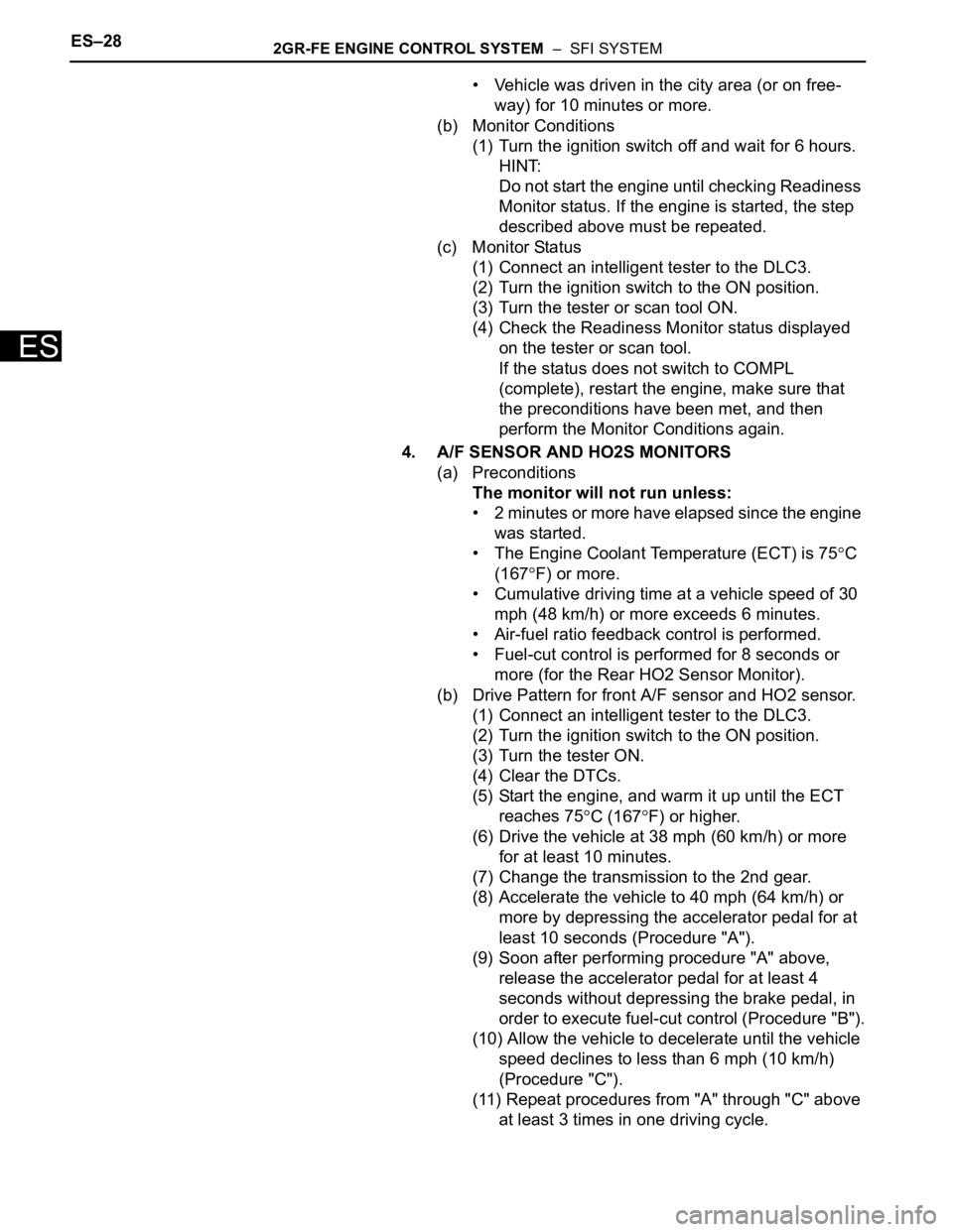
ES–282GR-FE ENGINE CONTROL SYSTEM – SFI SYSTEM
ES
• Vehicle was driven in the city area (or on free-
way) for 10 minutes or more.
(b) Monitor Conditions
(1) Turn the ignition switch off and wait for 6 hours.
HINT:
Do not start the engine until checking Readiness
Monitor status. If the engine is started, the step
described above must be repeated.
(c) Monitor Status
(1) Connect an intelligent tester to the DLC3.
(2) Turn the ignition switch to the ON position.
(3) Turn the tester or scan tool ON.
(4) Check the Readiness Monitor status displayed
on the tester or scan tool.
If the status does not switch to COMPL
(complete), restart the engine, make sure that
the preconditions have been met, and then
perform the Monitor Conditions again.
4. A/F SENSOR AND HO2S MONITORS
(a) Preconditions
The monitor will not run unless:
• 2 minutes or more have elapsed since the engine
was started.
• The Engine Coolant Temperature (ECT) is 75
C
(167
F) or more.
• Cumulative driving time at a vehicle speed of 30
mph (48 km/h) or more exceeds 6 minutes.
• Air-fuel ratio feedback control is performed.
• Fuel-cut control is performed for 8 seconds or
more (for the Rear HO2 Sensor Monitor).
(b) Drive Pattern for front A/F sensor and HO2 sensor.
(1) Connect an intelligent tester to the DLC3.
(2) Turn the ignition switch to the ON position.
(3) Turn the tester ON.
(4) Clear the DTCs.
(5) Start the engine, and warm it up until the ECT
reaches 75
C (167F) or higher.
(6) Drive the vehicle at 38 mph (60 km/h) or more
for at least 10 minutes.
(7) Change the transmission to the 2nd gear.
(8) Accelerate the vehicle to 40 mph (64 km/h) or
more by depressing the accelerator pedal for at
least 10 seconds (Procedure "A").
(9) Soon after performing procedure "A" above,
release the accelerator pedal for at least 4
seconds without depressing the brake pedal, in
order to execute fuel-cut control (Procedure "B").
(10) Allow the vehicle to decelerate until the vehicle
speed declines to less than 6 mph (10 km/h)
(Procedure "C").
(11) Repeat procedures from "A" through "C" above
at least 3 times in one driving cycle.
Page 382 of 3000
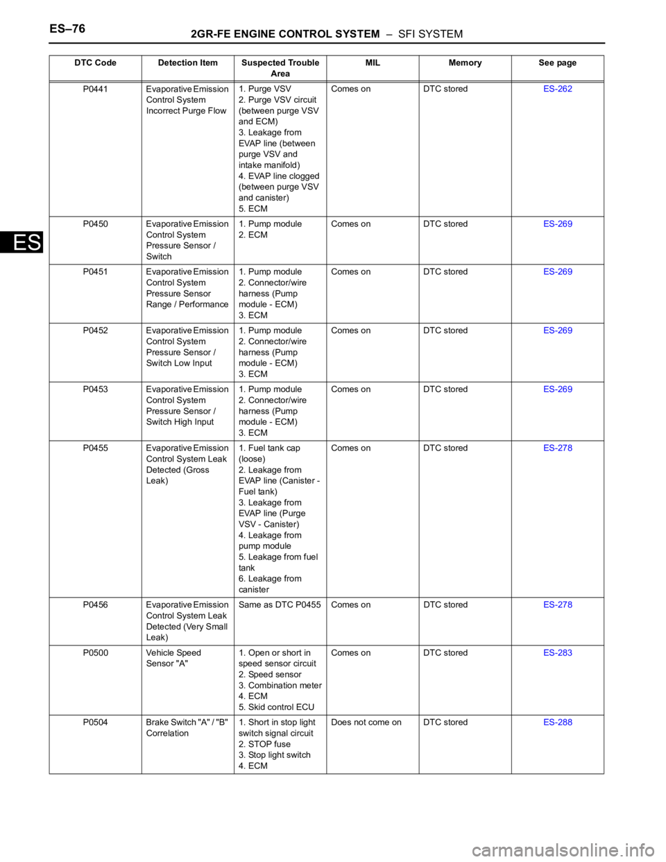
ES–762GR-FE ENGINE CONTROL SYSTEM – SFI SYSTEM
ES
P0441 Evaporative Emission
Control System
Incorrect Purge Flow1. Purge VSV
2. Purge VSV circuit
(between purge VSV
and ECM)
3. Leakage from
EVAP line (between
purge VSV and
intake manifold)
4. EVAP line clogged
(between purge VSV
and canister)
5. ECMComes on DTC storedES-262
P0450 Evaporative Emission
Control System
Pressure Sensor /
Switch1. Pump module
2. ECMComes on DTC storedES-269
P0451 Evaporative Emission
Control System
Pressure Sensor
Range / Performance1. Pump module
2. Connector/wire
harness (Pump
module - ECM)
3. ECMComes on DTC storedES-269
P0452 Evaporative Emission
Control System
Pressure Sensor /
Switch Low Input1. Pump module
2. Connector/wire
harness (Pump
module - ECM)
3. ECMComes on DTC storedES-269
P0453 Evaporative Emission
Control System
Pressure Sensor /
Switch High Input1. Pump module
2. Connector/wire
harness (Pump
module - ECM)
3. ECMComes on DTC storedES-269
P0455 Evaporative Emission
Control System Leak
Detected (Gross
Leak)1. Fuel tank cap
(loose)
2. Leakage from
EVAP line (Canister -
Fuel tank)
3. Leakage from
EVAP line (Purge
VSV - Canister)
4. Leakage from
pump module
5. Leakage from fuel
tank
6. Leakage from
canisterComes on DTC storedES-278
P0456 Evaporative Emission
Control System Leak
Detected (Very Small
Leak)Same as DTC P0455 Comes on DTC storedES-278
P0500 Vehicle Speed
Sensor "A"1. Open or short in
speed sensor circuit
2. Speed sensor
3. Combination meter
4. ECM
5. Skid control ECUComes on DTC storedES-283
P0504 Brake Switch "A" / "B"
Correlation1. Short in stop light
switch signal circuit
2. STOP fuse
3. Stop light switch
4. ECMDoes not come on DTC storedES-288 DTC Code Detection Item Suspected Trouble
AreaMIL Memory See page