brake TOYOTA SIENNA 2007 Service Owner's Guide
[x] Cancel search | Manufacturer: TOYOTA, Model Year: 2007, Model line: SIENNA, Model: TOYOTA SIENNA 2007Pages: 3000, PDF Size: 52.26 MB
Page 384 of 3000

ES–782GR-FE ENGINE CONTROL SYSTEM – SFI SYSTEM
ES
P0724 Brake Switch "B"
Circuit High1. Short in stop light
switch signal circuit
2. Stop light switch
3. ECMComes on DTC storedES-288
P2102 Throttle Actuator
Control Motor Circuit
Low1. Open in throttle
actuator circuit
2. Throttle actuator
3. ECMComes on DTC storedES-329
P2103 Throttle Actuator
Control Motor Circuit
High1. Short in throttle
actuator circuit
2. Throttle actuator
3. Throttle valve
4. Throttle body
5. ECMComes on DTC storedES-329
P2111 Throttle Actuator
Control System -
Stuck Open1. Throttle actuator
2. Throttle body
3. Throttle valveComes on DTC storedES-333
P2112 Throttle Actuator
Control System -
Stuck Closed1. Throttle actuator
2. Throttle body
3. Throttle valveComes on DTC storedES-333
P2118 Throttle Actuator
Control Motor Current
Range / Performance1. Open in ETCS
power source circuit
2. ETCS fuse
3. ECMComes on DTC storedES-336
P2119 Throttle Actuator
Control Throttle Body
Range / Performance1. ETCS
2. ECMComes on DTC storedES-340
P2120 Throttle / Pedal
Position Sensor /
Switch "D" Circuit1. Accelerator Pedal
Position (APP)
sensor
2. ECMComes on DTC storedES-343
P2121 Throttle / Pedal
Position Sensor /
Switch "D" Circuit
Range / Performance1. Accelerator
position (APP) sensor
2. ECMComes on DTC storedES-351
P2122 Throttle / Pedal
Position Sensor /
Switch "D" Circuit
Low Input1. APP sensor
2. Open in VCP1
circuit
3. Open or ground
short in VPA circuit
4. ECMComes on DTC storedES-343
P2123 Throttle / Pedal
Position Sensor /
Switch "D" Circuit
High Input1. APP sensor
2. Open in EPA circuit
3. ECMComes on DTC storedES-343
P2125 Throttle / Pedal
Position Sensor /
Switch "E" Circuit1. APP sensor
2. ECMComes on DTC storedES-343
P2127 Throttle / Pedal
Position Sensor /
Switch "E" Circuit
Low Input1. APP sensor
2. Open in VCP2
circuit
3. Open or ground
short in VPA2 circuit
4. ECMComes on DTC storedES-343
P2128 Throttle / Pedal
Position Sensor /
Switch "E" Circuit
High Input1. APP sensor
2. Open in EPA2
circuit
3. ECMComes on DTC storedES-343 DTC Code Detection Item Suspected Trouble
AreaMIL Memory See page
Page 589 of 3000
ES–2962GR-FE ENGINE CONTROL SYSTEM – SFI SYSTEM
ES
DESCRIPTION
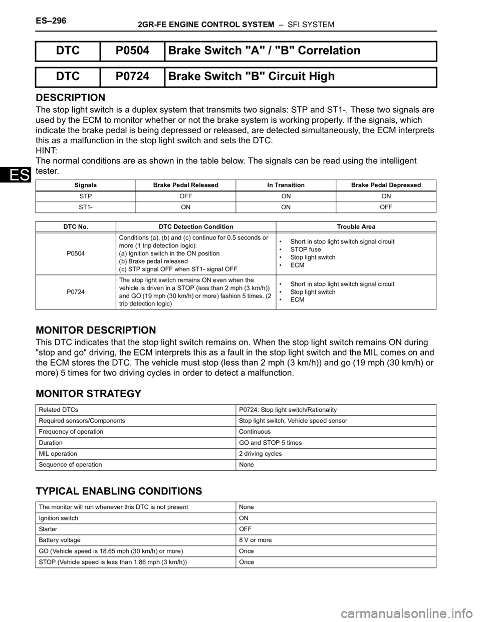
The stop light switch is a duplex system that transmits two signals: STP and ST1-. These two signals are
used by the ECM to monitor whether or not the brake system is working properly. If the signals, which
indicate the brake pedal is being depressed or released, are detected simultaneously, the ECM interprets
this as a malfunction in the stop light switch and sets the DTC.
HINT:
The normal conditions are as shown in the table below. The signals can be read using the intelligent
tester.
MONITOR DESCRIPTION
This DTC indicates that the stop light switch remains on. When the stop light switch remains ON during
"stop and go" driving, the ECM interprets this as a fault in the stop light switch and the MIL comes on and
the ECM stores the DTC. The vehicle must stop (less than 2 mph (3 km/h)) and go (19 mph (30 km/h) or
more) 5 times for two driving cycles in order to detect a malfunction.
MONITOR STRATEGY
TYPICAL ENABLING CONDITIONS
DTC P0504 Brake Switch "A" / "B" Correlation
DTC P0724 Brake Switch "B" Circuit High
Signals Brake Pedal Released In Transition Brake Pedal Depressed
STP OFF ON ON
ST1- ON ON OFF
DTC No. DTC Detection Condition Trouble Area
P0504Conditions (a), (b) and (c) continue for 0.5 seconds or
more (1 trip detection logic):
(a) Ignition switch in the ON position
(b) Brake pedal released
(c) STP signal OFF when ST1- signal OFF• Short in stop light switch signal circuit
• STOP fuse
• Stop light switch
•ECM
P0724The stop light switch remains ON even when the
vehicle is driven in a STOP (less than 2 mph (3 km/h))
and GO (19 mph (30 km/h) or more) fashion 5 times. (2
trip detection logic)• Short in stop light switch signal circuit
• Stop light switch
•ECM
Related DTCs P0724: Stop light switch/Rationality
Required sensors/Components Stop light switch, Vehicle speed sensor
Frequency of operation Continuous
Duration GO and STOP 5 times
MIL operation 2 driving cycles
Sequence of operation None
The monitor will run whenever this DTC is not present None
Ignition switch ON
Starter OFF
Battery voltage 8 V or more
GO (Vehicle speed is 18.65 mph (30 km/h) or more) Once
STOP (Vehicle speed is less than 1.86 mph (3 km/h)) Once
Page 590 of 3000
2GR-FE ENGINE CONTROL SYSTEM – SFI SYSTEMES–297
ES
TYPICAL MALFUNCTION THRESHOLDS
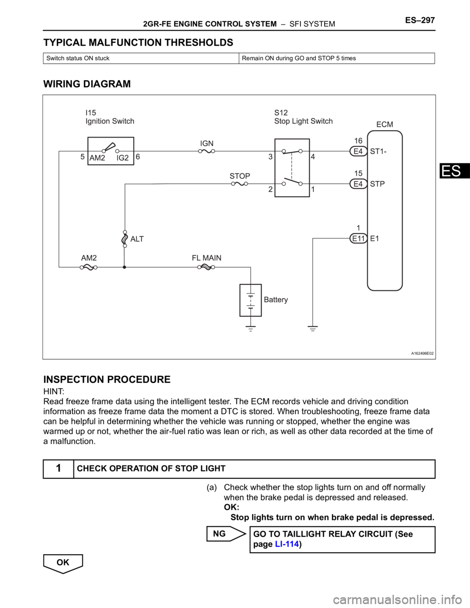
WIRING DIAGRAM
INSPECTION PROCEDURE
HINT:
Read freeze frame data using the intelligent tester. The ECM records vehicle and driving condition
information as freeze frame data the moment a DTC is stored. When troubleshooting, freeze frame data
can be helpful in determining whether the vehicle was running or stopped, whether the engine was
warmed up or not, whether the air-fuel ratio was lean or rich, as well as other data recorded at the time of
a malfunction.
(a) Check whether the stop lights turn on and off normally
when the brake pedal is depressed and released.
OK:
Stop lights turn on when brake pedal is depressed.
NG
OK
Switch status ON stuck Remain ON during GO and STOP 5 times
1CHECK OPERATION OF STOP LIGHT
A162496E02
GO TO TAILLIGHT RELAY CIRCUIT (See
page LI-114)
Page 591 of 3000
ES–2982GR-FE ENGINE CONTROL SYSTEM – SFI SYSTEM
ES
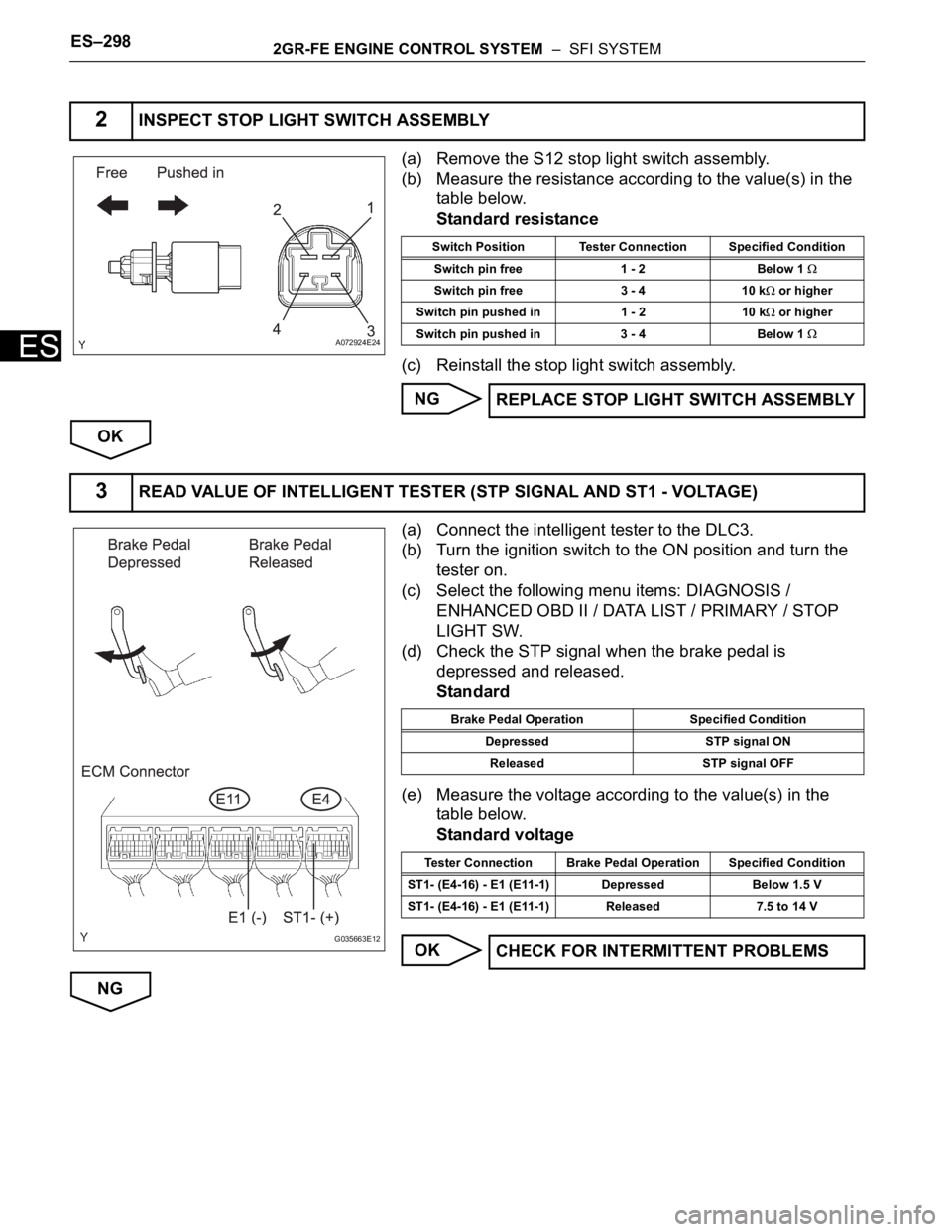
(a) Remove the S12 stop light switch assembly.
(b) Measure the resistance according to the value(s) in the
table below.
Standard resistance
(c) Reinstall the stop light switch assembly.
NG
OK
(a) Connect the intelligent tester to the DLC3.
(b) Turn the ignition switch to the ON position and turn the
tester on.
(c) Select the following menu items: DIAGNOSIS /
ENHANCED OBD II / DATA LIST / PRIMARY / STOP
LIGHT SW.
(d) Check the STP signal when the brake pedal is
depressed and released.
Standard
(e) Measure the voltage according to the value(s) in the
table below.
Standard voltage
OK
NG
2INSPECT STOP LIGHT SWITCH ASSEMBLY
A072924E24
Switch Position Tester Connection Specified Condition
Switch pin free 1 - 2 Below 1
Switch pin free 3 - 4 10 k or higher
Switch pin pushed in 1 - 2 10 k
or higher
Switch pin pushed in 3 - 4 Below 1
REPLACE STOP LIGHT SWITCH ASSEMBLY
3READ VALUE OF INTELLIGENT TESTER (STP SIGNAL AND ST1 - VOLTAGE)
G035663E12
Brake Pedal Operation Specified Condition
Depressed STP signal ON
Released STP signal OFF
Tester Connection Brake Pedal Operation Specified Condition
ST1- (E4-16) - E1 (E11-1) Depressed Below 1.5 V
ST1- (E4-16) - E1 (E11-1) Released 7.5 to 14 V
CHECK FOR INTERMITTENT PROBLEMS
Page 615 of 3000

ES–3222GR-FE ENGINE CONTROL SYSTEM – SFI SYSTEM
ES
DESCRIPTION
The ECM continuously monitors its internal processors (CPUs), A/F sensor transistors and heated oxygen
sensor (HO2S) transistors. This self-check ensures that the ECM is functioning properly. These are
diagnosed by internal "mirroring" of the main and sub CPUs to detect the processors error. If outputs from
the processors deviate from the standards, the ECM will illuminate the MIL and set a DTC immediately.
MONITOR STRATEGY
TYPICAL ENABLING CONDITIONS
TYPICAL MALFUNCTION THRESHOLDS
INSPECTION PROCEDURE
(a) Allow the engine to idle.
(b) Check for exhaust gas leak around the heated oxygen
sensor.
OK:
No leak from the heated oxygen sensor.
NG
DTC P0606 ECM / PCM Processor
DTC DTC Setting Condition Trouble Area
P0606• ECM CPUs malfunction
• A/F sensor transistors malfunction
• HO2S transistors malfunction• Exhaust gas leak
•HO2 Sensor
•ECM
Related DTC P0606: ECM range check
Required sensors/Components (main) ECM
Required sensors/Components (sub)APP sensor, TP sensor, Brake switch, Cruise control, A/F sensor,
HO2 sensor
Frequency of Operation Continuous
Duration 60 seconds
MIL Operation Immediate
Sequence of Operation None
Monitor runs whenever the following DTCs are not present None
Engine Running
Estimated A/F sensor temperature 450 to 800
C (842 to 1472F)
Estimated HO2S temperature 450 to 800
C (842 to 1472F)
Difference of main APP and sub APP 0.3 V or more
Difference of main TP and sub TP 0.3 V or more
Difference of main brake switch signal and sub brake switch signal Different
Cruise control Fail
A/F sensor transistors Fail
HO2S transistors Fail
1INSPECT FOR EXHAUST GAS LEAK
REPAIR OR REPLACE EXHAUST GAS
LEAKAGE POINT
Page 643 of 3000
ES–3502GR-FE ENGINE CONTROL SYSTEM – SFI SYSTEM
ES
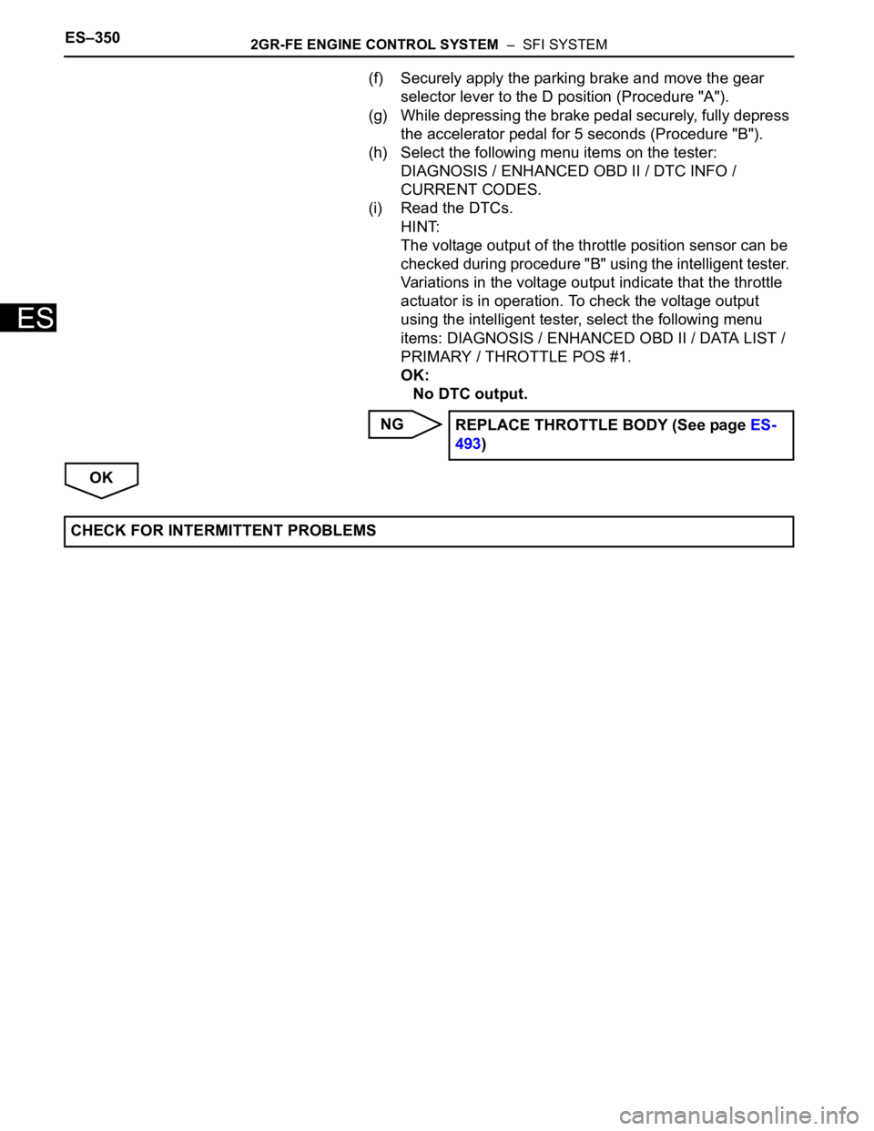
(f) Securely apply the parking brake and move the gear
selector lever to the D position (Procedure "A").
(g) While depressing the brake pedal securely, fully depress
the accelerator pedal for 5 seconds (Procedure "B").
(h) Select the following menu items on the tester:
DIAGNOSIS / ENHANCED OBD II / DTC INFO /
CURRENT CODES.
(i) Read the DTCs.
HINT:
The voltage output of the throttle position sensor can be
checked during procedure "B" using the intelligent tester.
Variations in the voltage output indicate that the throttle
actuator is in operation. To check the voltage output
using the intelligent tester, select the following menu
items: DIAGNOSIS / ENHANCED OBD II / DATA LIST /
PRIMARY / THROTTLE POS #1.
OK:
No DTC output.
NG
OKREPLACE THROTTLE BODY (See page ES-
493)
CHECK FOR INTERMITTENT PROBLEMS
Page 662 of 3000

2GR-FE ENGINE CONTROL SYSTEM – SFI SYSTEMES–369
ES
9. Drive the vehicle at a proper vehicle speed to perform fuel-cut operation (refer to the following HINT)
(Procedure "D").
HINT:
Fuel-cut is performed when the following conditions are met:
• Accelerator pedal is fully released.
• Engine speed is 2500 rpm or more (fuel injection resumes at 1000 rpm).
10. Accelerate the vehicle to 40 mph (64 km/h) or more by depressing the accelerator pedal for at least 10
seconds (Procedure "E").
11. Soon after performing procedure "J" on the previous page, release the accelerator pedal for at least 4
seconds without depressing the brake pedal, in order to execute fuel-cut control (Procedure "F").
12. Allow the vehicle to decelerate until the vehicle speed declines to less than 6 mph (10 km/h).
13. Repeat procedures from "H" through "K" in this section at least 3 times per driving cycle.
HINT:
Completion of all A/F sensor monitors is required to change the value in TEST RESULT.
CAUTION:
Strictly observe posted speed limits, traffic laws, and road conditions when performing these
driving patterns.
INSPECTION PROCEDURE
HINT:
Malfunctioning areas can be identified by performing the A/F CONTROL function provided in the ACTIVE
TEST. The A/F CONTROL function can help to determine whether the Air-Fuel Ratio (A/F) sensor, Heated
Oxygen (HO2) sensor and other potential trouble areas are malfunctioning.
The following instructions describe how to conduct the A/F CONTROL operation using an intelligent
tester.
(a) Connect the intelligent tester to the DLC3.
(b) Start the engine and turn the tester on.
(c) Warm up the engine at an engine speed of 2500 rpm for approximately 90 seconds.
(d) Select the following menu items on the tester: DIAGNOSIS / ENHANCED OBD II / ACTIVE TEST / A/
F CONTROL.
(e) Perform the A/F CONTROL operation with the engine in an idling condition (press the RIGHT or LEFT
button to change the fuel injection volume).
(f) Monitor the voltage outputs of the A/F and HO2 sensors (AFS B1S1 and O2S B1S2 or AFS B2S1 and
O2S B2S2) displayed on the tester.
HINT:
• The A/F CONTROL operation lowers the fuel injection volume by 12.5% or increases the injection
volume by 25%.
• Each sensor reacts in accordance with increases and decreases in the fuel injection volume.
Standard voltage
NOTICE:
The Air-Fuel Ratio (A/F) sensor has an output delay of a few seconds and the Heated Oxygen
(HO2) sensor has a maximum output delay of approximately 20 seconds.
Tester Display (Sensor) Injection Volumes Status Voltages
AFS B1S1 or AFS B2S1 (A/F) +25% Rich Less than 3.0
AFS B1S1 or AFS B2S1 (A/F) -12.5% Lean More than 3.35
O2S B1S2 or O2S B2S2 (HO2) +25% Rich More than 0.55
O2S B1S2 or O2S B2S2 (HO2) -12.5% Lean Less than 0.4
Page 804 of 3000
ES–282GR-FE ENGINE CONTROL SYSTEM – SFI SYSTEM
ES
• Vehicle was driven in the city area (or on free-
way) for 10 minutes or more.
(b) Monitor Conditions
(1) Turn the ignition switch off and wait for 6 hours.
HINT:
Do not start the engine until checking Readiness
Monitor status. If the engine is started, the step
described above must be repeated.
(c) Monitor Status
(1) Connect an intelligent tester to the DLC3.
(2) Turn the ignition switch to the ON position.
(3) Turn the tester or scan tool ON.
(4) Check the Readiness Monitor status displayed
on the tester or scan tool.
If the status does not switch to COMPL
(complete), restart the engine, make sure that
the preconditions have been met, and then
perform the Monitor Conditions again.
4. A/F SENSOR AND HO2S MONITORS
(a) Preconditions
The monitor will not run unless:
• 2 minutes or more have elapsed since the engine
was started.
• The Engine Coolant Temperature (ECT) is 75
C
(167
F) or more.
• Cumulative driving time at a vehicle speed of 30
mph (48 km/h) or more exceeds 6 minutes.
• Air-fuel ratio feedback control is performed.
• Fuel-cut control is performed for 8 seconds or
more (for the Rear HO2 Sensor Monitor).
(b) Drive Pattern for front A/F sensor and HO2 sensor.
(1) Connect an intelligent tester to the DLC3.
(2) Turn the ignition switch to the ON position.
(3) Turn the tester ON.
(4) Clear the DTCs.
(5) Start the engine, and warm it up until the ECT
reaches 75
C (167F) or higher.
(6) Drive the vehicle at 38 mph (60 km/h) or more
for at least 10 minutes.
(7) Change the transmission to the 2nd gear.
(8) Accelerate the vehicle to 40 mph (64 km/h) or
more by depressing the accelerator pedal for at
least 10 seconds (Procedure "A").
(9) Soon after performing procedure "A" above,
release the accelerator pedal for at least 4
seconds without depressing the brake pedal, in
order to execute fuel-cut control (Procedure "B").
(10) Allow the vehicle to decelerate until the vehicle
speed declines to less than 6 mph (10 km/h)
(Procedure "C").
(11) Repeat procedures from "A" through "C" above
at least 3 times in one driving cycle.
Page 813 of 3000
2GR-FE ENGINE CONTROL SYSTEM – SFI SYSTEMES–33
ES
TERMINALS OF ECM
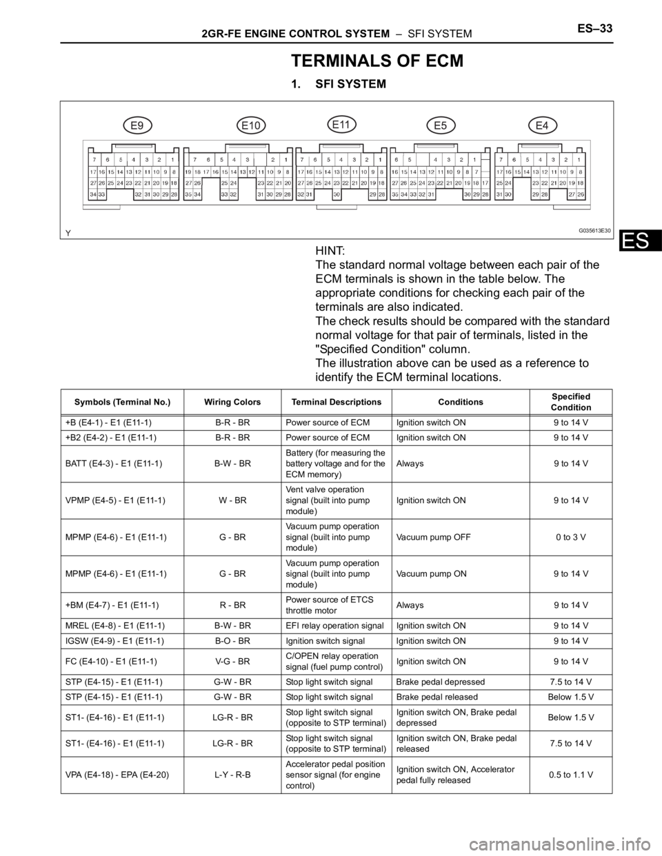
1. SFI SYSTEM
HINT:
The standard normal voltage between each pair of the
ECM terminals is shown in the table below. The
appropriate conditions for checking each pair of the
terminals are also indicated.
The check results should be compared with the standard
normal voltage for that pair of terminals, listed in the
"Specified Condition" column.
The illustration above can be used as a reference to
identify the ECM terminal locations.
G035613E30
Symbols (Terminal No.) Wiring Colors Terminal Descriptions ConditionsSpecified
Condition
+B (E4-1) - E1 (E11-1) B-R - BR Power source of ECM Ignition switch ON 9 to 14 V
+B2 (E4-2) - E1 (E11-1) B-R - BR Power source of ECM Ignition switch ON 9 to 14 V
BATT (E4-3) - E1 (E11-1) B-W - BRBattery (for measuring the
battery voltage and for the
ECM memory)Always 9 to 14 V
VPMP (E4-5) - E1 (E11-1) W - BRVent valve operation
signal (built into pump
module)Ignition switch ON 9 to 14 V
MPMP (E4-6) - E1 (E11-1) G - BRVacuum pump operation
signal (built into pump
module)Vacuum pump OFF 0 to 3 V
MPMP (E4-6) - E1 (E11-1) G - BRVacuum pump operation
signal (built into pump
module)Vacuum pump ON 9 to 14 V
+BM (E4-7) - E1 (E11-1) R - BRPower source of ETCS
throttle motorAlways 9 to 14 V
MREL (E4-8) - E1 (E11-1) B-W - BR EFI relay operation signal Ignition switch ON 9 to 14 V
IGSW (E4-9) - E1 (E11-1) B-O - BRIgnition switch signal Ignition switch ON 9 to 14 V
FC (E4-10) - E1 (E11-1) V-G - BRC/OPEN relay operation
signal (fuel pump control)Ignition switch ON 9 to 14 V
STP (E4-15) - E1 (E11-1) G-W - BR Stop light switch signal Brake pedal depressed 7.5 to 14 V
STP (E4-15) - E1 (E11-1) G-W - BR Stop light switch signal Brake pedal released Below 1.5 V
ST1- (E4-16) - E1 (E11-1) LG-R - BRStop light switch signal
(opposite to STP terminal)Ignition switch ON, Brake pedal
depressedBelow 1.5 V
ST1- (E4-16) - E1 (E11-1) LG-R - BRStop light switch signal
(opposite to STP terminal)Ignition switch ON, Brake pedal
released7.5 to 14 V
VPA (E4-18) - EPA (E4-20) L-Y - R-BAccelerator pedal position
sensor signal (for engine
control)Ignition switch ON, Accelerator
pedal fully released0.5 to 1.1 V
Page 934 of 3000
EM–42GR-FE ENGINE MECHANICAL – ENGINE
EM
(h) Install the 6 ignition coils.
Torque: 10 N*m (102 kgf*cm, 7 ft.*lbf)
(i) Install the intake air surge tank (See page ES-522).
10. INSPECT CO/HC
(a) Start the engine.
(b) Run the engine at 2500 rpm for approximately 180
seconds.
(c) Insert the CO/HC meter testing probe at least 40 cm
(1.3 ft.) into the tailpipe during idling.
(d) Check CO/HC concentration at idle and/or 2500
rpm.
HINT:
Check regulations and restrictions in your area
when performing 2 mode CO/HC concentration
testing (engine check at both idle speed and at 2500
rpm).
If the CO/HC concentration does not comply with
regulations, perform troubleshooting in the order
given below.
(1) Check air fuel ratio sensor and heated oxygen
sensor operation.
(2) See the table below for possible causes, and
then inspect and repair.
CO HC Problems Causes
Normal High Rough idle1. Faulty ignitions:
– Incorrect timing
– Fouled, shorted or improperly gapped plugs
2. Incorrect valve clearance
3. Leaks in intake and exhaust valves
4. Leaks in cylinders
Low HighRough idle
(fluctuating HC reading)1. Vacuum leaks:
– PCV hoses
– Intake manifold
– Throttle body
– Brake booster line
2. Lean mixture causing misfire
High HighRough idle
(black smoke from exhaust)1. Restricted air filter
2. Plugged PCV valve
3. Faulty SFI system:
– Faulty fuel pressure regulator
– Defective ECT sensor
– Defective MAF meter
–Faulty ECM
– Faulty injectors
– Faulty throttle position sensor