brake TOYOTA SIENNA 2007 Service Workshop Manual
[x] Cancel search | Manufacturer: TOYOTA, Model Year: 2007, Model line: SIENNA, Model: TOYOTA SIENNA 2007Pages: 3000, PDF Size: 52.26 MB
Page 1429 of 3000
U151E AUTOMATIC TRANSAXLE – AUTOMATIC TRANSAXLE SYSTEMAX–63
AX
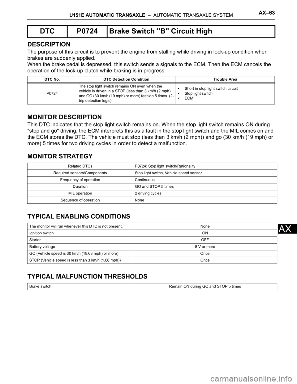
DESCRIPTION
The purpose of this circuit is to prevent the engine from stalling while driving in lock-up condition when
brakes are suddenly applied.
When the brake pedal is depressed, this switch sends a signals to the ECM. Then the ECM cancels the
operation of the lock-up clutch while braking is in progress.
MONITOR DESCRIPTION
This DTC indicates that the stop light switch remains on. When the stop light switch remains ON during
"stop and go" driving, the ECM interprets this as a fault in the stop light switch and the MIL comes on and
the ECM stores the DTC. The vehicle must stop (less than 3 km/h (2 mph)) and go (30 km/h (19 mph) or
more) 5 times for two driving cycles in order to detect a malfunction.
MONITOR STRATEGY
TYPICAL ENABLING CONDITIONS
TYPICAL MALFUNCTION THRESHOLDS
DTC P0724 Brake Switch "B" Circuit High
DTC No. DTC Detection Condition Trouble Area
P0724The stop light switch remains ON even when the
vehicle is driven in a STOP (less than 3 km/h (2 mph)
and GO (30 km/h (19 mph) or more) fashion 5 times. (2-
trip detection logic).• Short in stop light switch circuit
• Stop light switch
•ECM
Related DTCs P0724: Stop light switch/Rationality
Required sensors/Components Stop light switch, Vehicle speed sensor
Frequency of operation Continuous
Duration GO and STOP 5 times
MIL operation 2 driving cycles
Sequence of operation None
The monitor will run whenever this DTC is not present. None
Ignition switchON
Sta r t e rOFF
Battery voltage8 V or more
GO (Vehicle speed is 30 km/h (18.63 mph) or more) Once
STOP (Vehicle speed is less than 3 km/h (1.86 mph)) Once
Brake switch Remain ON during GO and STOP 5 times
Page 1431 of 3000

U151E AUTOMATIC TRANSAXLE – AUTOMATIC TRANSAXLE SYSTEMAX–65
AX
(g) According to the display on the tester, read the "DATA
LIST".
NOTICE:
In the table below, the value listed under "Normal
Condition" are reference values. Do not depend
solely on these reference values when deciding
whether apart is faulty or not.
Result
B
A
(a) Remove the stop light switch assembly.
(b) Measure the resistance according to the value(s) in the
table below.
Standard resistance
NG
OK
(a) Install the stop light switch assembly.
(b) Measure the voltage according to the value(s) in the
table below when the brake pedal is depressed and
released.
Standard voltage
NG
Tester Display Measurement Item/Range Normal Condition Diagnostic Note
STOP LIGHT SWStop light switch Status/
ON or OFF• Brake Pedal is depressed:
ON
• Brake Pedal is released: OFF-
Result Proceed to
NG A
OK B
Go to step 3
2INSPECT STOP LIGHT SWITCH ASSEMBLY
E065594E39
Switch position Tester Connection Specified Condition
Switch pin free 1 - 2 Below 1
Switch pin pushed in10 k or higher
Switch pin free 3 - 4 10 k
or higher
Switch pin pushed in
Below 1
REPLACE STOP LIGHT SWITCH ASSEMBLY
3CHECK HARNESS AND CONNECTOR (STOP LIGHT SWITCH ASSEMBLY - ECM)
G035619E25
Condition Tester Connection Specified Condition
Brake pedal is
depressedE4-15 (STP) - Body
ground11 to 14 V
Brake pedal is released Below 1 V
REPAIR OR REPLACE HARNESS OR
CONNECTOR
Page 1433 of 3000
U151E AUTOMATIC TRANSAXLE – AUTOMATIC TRANSAXLE SYSTEMAX–67
AX
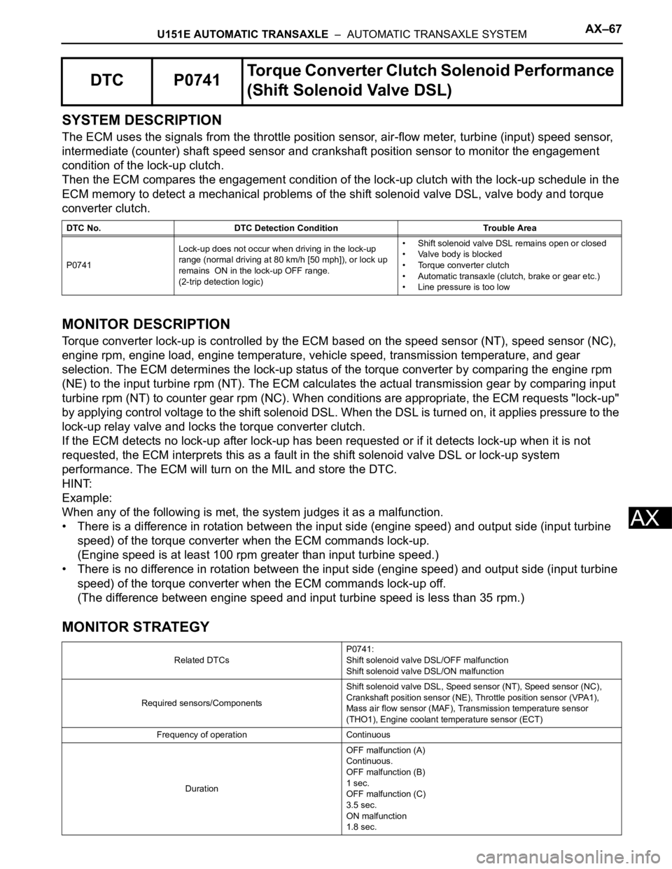
SYSTEM DESCRIPTION
The ECM uses the signals from the throttle position sensor, air-flow meter, turbine (input) speed sensor,
intermediate (counter) shaft speed sensor and crankshaft position sensor to monitor the engagement
condition of the lock-up clutch.
Then the ECM compares the engagement condition of the lock-up clutch with the lock-up schedule in the
ECM memory to detect a mechanical problems of the shift solenoid valve DSL, valve body and torque
converter clutch.
MONITOR DESCRIPTION
Torque converter lock-up is controlled by the ECM based on the speed sensor (NT), speed sensor (NC),
engine rpm, engine load, engine temperature, vehicle speed, transmission temperature, and gear
selection. The ECM determines the lock-up status of the torque converter by comparing the engine rpm
(NE) to the input turbine rpm (NT). The ECM calculates the actual transmission gear by comparing input
turbine rpm (NT) to counter gear rpm (NC). When conditions are appropriate, the ECM requests "lock-up"
by applying control voltage to the shift solenoid DSL. When the DSL is turned on, it applies pressure to the
lock-up relay valve and locks the torque converter clutch.
If the ECM detects no lock-up after lock-up has been requested or if it detects lock-up when it is not
requested, the ECM interprets this as a fault in the shift solenoid valve DSL or lock-up system
performance. The ECM will turn on the MIL and store the DTC.
HINT:
Example:
When any of the following is met, the system judges it as a malfunction.
• There is a difference in rotation between the input side (engine speed) and output side (input turbine
speed) of the torque converter when the ECM commands lock-up.
(Engine speed is at least 100 rpm greater than input turbine speed.)
• There is no difference in rotation between the input side (engine speed) and output side (input turbine
speed) of the torque converter when the ECM commands lock-up off.
(The difference between engine speed and input turbine speed is less than 35 rpm.)
MONITOR STRATEGY
DTC P0741Torque Converter Clutch Solenoid Performance
(Shift Solenoid Valve DSL)
DTC No. DTC Detection Condition Trouble Area
P0741Lock-up does not occur when driving in the lock-up
range (normal driving at 80 km/h [50 mph]), or lock up
remains ON in the lock-up OFF range.
(2-trip detection logic)• Shift solenoid valve DSL remains open or closed
• Valve body is blocked
• Torque converter clutch
• Automatic transaxle (clutch, brake or gear etc.)
• Line pressure is too low
Related DTCsP0741:
Shift solenoid valve DSL/OFF malfunction
Shift solenoid valve DSL/ON malfunction
Required sensors/ComponentsShift solenoid valve DSL, Speed sensor (NT), Speed sensor (NC),
Crankshaft position sensor (NE), Throttle position sensor (VPA1),
Mass air flow sensor (MAF), Transmission temperature sensor
(THO1), Engine coolant temperature sensor (ECT)
Frequency of operation Continuous
DurationOFF malfunction (A)
Continuous.
OFF malfunction (B)
1 sec.
OFF malfunction (C)
3.5 sec.
ON malfunction
1.8 sec.
Page 1439 of 3000
U151E AUTOMATIC TRANSAXLE – AUTOMATIC TRANSAXLE SYSTEMAX–73
AX
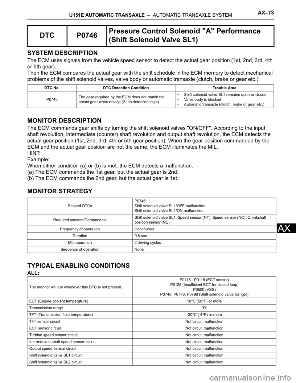
SYSTEM DESCRIPTION
The ECM uses signals from the vehicle speed sensor to detect the actual gear position (1st, 2nd, 3rd, 4th
or 5th gear).
Then the ECM compares the actual gear with the shift schedule in the ECM memory to detect mechanical
problems of the shift solenoid valves, valve body or automatic transaxle (clutch, brake or gear etc.).
MONITOR DESCRIPTION
The ECM commands gear shifts by turning the shift solenoid valves "ON/OFF". According to the input
shaft revolution, intermediate (counter) shaft revolution and output shaft revolution, the ECM detects the
actual gear position (1st, 2nd, 3rd, 4th or 5th gear position). When the gear position commanded by the
ECM and the actual gear position are not the same, the ECM illuminates the MIL.
HINT:
Example:
When either condition (a) or (b) is met, the ECM detects a malfunction.
(a) The ECM commands the 1st gear, but the actual gear is 2nd.
(b) The ECM commands the 2nd gear, but the actual gear is 1st.
MONITOR STRATEGY
TYPICAL ENABLING CONDITIONS
ALL:
DTC P0746Pressure Control Solenoid "A" Performance
(Shift Solenoid Valve SL1)
DTC No. DTC Detection Condition Trouble Area
P0746The gear required by the ECM does not match the
actual gear when driving (2-trip detection logic)• Shift solenoid valve SL1 remains open or closed
• Valve body is blocked
• Automatic transaxle (clutch, brake or gear etc.)
Related DTCsP0746:
Shift solenoid valve SL1/OFF malfunction
Shift solenoid valve SL1/ON malfunction
Required sensors/ComponentsShift solenoid valve SL1, Speed sensor (NT), Speed sensor (NC), Crankshaft
position sensor (NE)
Frequency of operation Continuous
Duration 0.8 sec.
MIL operation 2 driving cycles
Sequence of operation None
The monitor will run whenever this DTC is not present.P0115 - P0118 (ECT sensor)
P0125 (Insufficient ECT for closed loop)
P0500 (VSS)
P0748, P0778, P0798 (Shift solenoid valve (range))
ECT (Engine coolant temperature) 10
C (50F) or more
Transmission range"D"
TFT (Transmission fluid temperature) -20
C (-4F) or more
TFT sensor circuitNot circuit malfunction
ECT sensor circuitNot circuit malfunction
Turbine speed sensor circuit Not circuit malfunction
Intermediate shaft speed sensor circuit Not circuit malfunction
Output speed sensor circuit Not circuit malfunction
Shift solenoid valve SL1 circuit Not circuit malfunction
Shift solenoid valve SL2 circuit Not circuit malfunction
Page 1447 of 3000
U151E AUTOMATIC TRANSAXLE – AUTOMATIC TRANSAXLE SYSTEMAX–81
AX
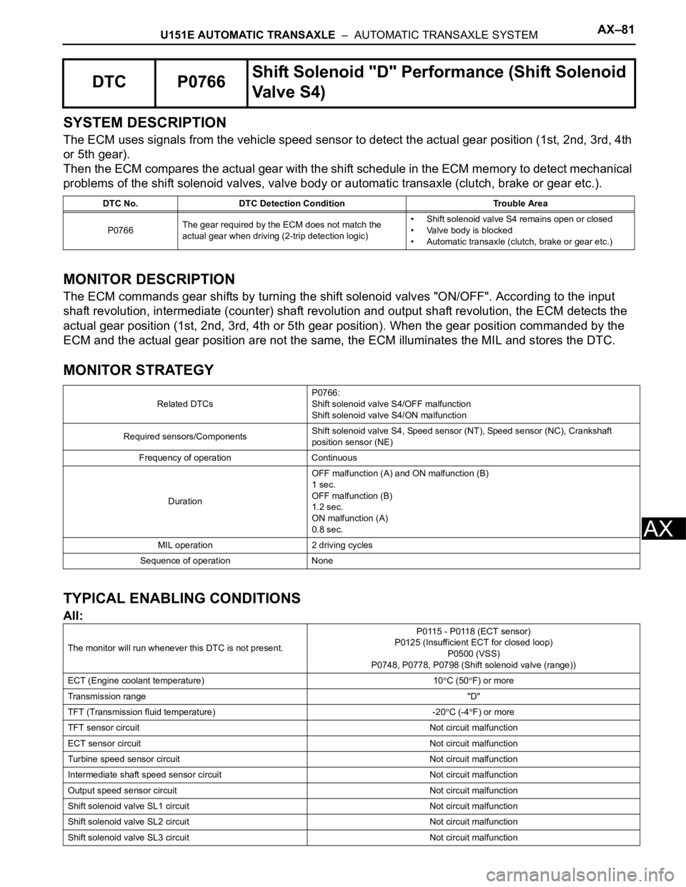
SYSTEM DESCRIPTION
The ECM uses signals from the vehicle speed sensor to detect the actual gear position (1st, 2nd, 3rd, 4th
or 5th gear).
Then the ECM compares the actual gear with the shift schedule in the ECM memory to detect mechanical
problems of the shift solenoid valves, valve body or automatic transaxle (clutch, brake or gear etc.).
MONITOR DESCRIPTION
The ECM commands gear shifts by turning the shift solenoid valves "ON/OFF". According to the input
shaft revolution, intermediate (counter) shaft revolution and output shaft revolution, the ECM detects the
actual gear position (1st, 2nd, 3rd, 4th or 5th gear position). When the gear position commanded by the
ECM and the actual gear position are not the same, the ECM illuminates the MIL and stores the DTC.
MONITOR STRATEGY
TYPICAL ENABLING CONDITIONS
All:
DTC P0766Shift Solenoid "D" Performance (Shift Solenoid
Valve S4)
DTC No. DTC Detection Condition Trouble Area
P0766The gear required by the ECM does not match the
actual gear when driving (2-trip detection logic)• Shift solenoid valve S4 remains open or closed
• Valve body is blocked
• Automatic transaxle (clutch, brake or gear etc.)
Related DTCsP0766:
Shift solenoid valve S4/OFF malfunction
Shift solenoid valve S4/ON malfunction
Required sensors/ComponentsShift solenoid valve S4, Speed sensor (NT), Speed sensor (NC), Crankshaft
position sensor (NE)
Frequency of operation Continuous
DurationOFF malfunction (A) and ON malfunction (B)
1 sec.
OFF malfunction (B)
1.2 sec.
ON malfunction (A)
0.8 sec.
MIL operation 2 driving cycles
Sequence of operation None
The monitor will run whenever this DTC is not present.P0115 - P0118 (ECT sensor)
P0125 (Insufficient ECT for closed loop)
P0500 (VSS)
P0748, P0778, P0798 (Shift solenoid valve (range))
ECT (Engine coolant temperature) 10
C (50F) or more
Transmission range"D"
TFT (Transmission fluid temperature) -20
C (-4F) or more
TFT sensor circuitNot circuit malfunction
ECT sensor circuitNot circuit malfunction
Turbine speed sensor circuit Not circuit malfunction
Intermediate shaft speed sensor circuit Not circuit malfunction
Output speed sensor circuit Not circuit malfunction
Shift solenoid valve SL1 circuit Not circuit malfunction
Shift solenoid valve SL2 circuit Not circuit malfunction
Shift solenoid valve SL3 circuit Not circuit malfunction
Page 1451 of 3000
U151E AUTOMATIC TRANSAXLE – AUTOMATIC TRANSAXLE SYSTEMAX–85
AX
SYSTEM DESCRIPTION
The ECM uses signals from the vehicle speed sensor to detect the actual gear position (1st, 2nd, 3rd, 4th
or 5th gear).
Then the ECM compares the actual gear with the shift schedule in the ECM memory to detect mechanical
problems of the shift solenoid valves, valve body or automatic transaxle (clutch, brake or gear etc.).
MONITOR DESCRIPTION
The ECM commands gear shifts by turning the shift solenoid valves "ON/OFF". According to the input
shaft revolution, intermediate (counter) shaft revolution and output shaft revolution, the ECM detects the
actual gear position (1st, 2nd, 3rd, 4th or 5th gear position). When the gear position commanded by the
ECM and the actual gear position are not the same, the ECM illuminates the MIL and stores the DTC.
MONITOR STRATEGY
TYPICAL ENABLING CONDITIONS
All:
DTC P0771Shift Solenoid "E" Performance (Shift Solenoid
Va l v e S R )
DTC No. DTC Detection Condition Trouble Area
P0771The gear required by the ECM does not match the
actual gear when driving (2-trip detection logic)• Shift solenoid valve SR remains open or closed
• Valve body is blocked
• Automatic transaxle (clutch, brake or gear etc.)
Related DTCsP0771:
Shift solenoid valve SR/Rationality check
Required sensors/ComponentsShift solenoid valve SR, Speed sensor (NT), Speed sensor (NC), Crankshaft
position sensor (NE)
Frequency of operation Continuous
DurationOFF malfunction (A)
1 sec.
OFF malfunction (B)
3.5 sec.
ON malfunction (A)
Continuous
ON malfunction (B) and (C)
0.8 sec.
MIL operation 2 driving cycles
Sequence of operation None
The monitor will run whenever this DTC is not presentP0115 - P0118 (ECT sensor)
P0125 (Insufficient ECT for closed loop)
P0500 (VSS)
P0748, P0778, P0798 (Shift solenoid valve (range))
ECT (Engine coolant temperature) 10
C (50F) or more
Transmission range"D"
TFT (Transmission fluid temperature) -20
C (-4F) or more
TFT sensor circuitNot circuit malfunction
ECT sensor circuitNot circuit malfunction
Turbine speed sensor circuit Not circuit malfunction
Intermediate shaft speed sensor circuit Not circuit malfunction
Output speed sensor circuit Not circuit malfunction
Shift solenoid valve SL1 circuit Not circuit malfunction
Shift solenoid valve SL2 circuit Not circuit malfunction
Page 1455 of 3000

U151E AUTOMATIC TRANSAXLE – AUTOMATIC TRANSAXLE SYSTEMAX–89
AX
SYSTEM DESCRIPTION
The ECM uses signals from the vehicle speed sensor to detect the actual gear position (1st, 2nd, 3rd, 4th
or 5th gear).
Then the ECM compares the actual gear with the shift schedule in the ECM memory to detect mechanical
problems of the shift solenoid valves, valve body or automatic transaxle (clutch, brake or gear etc.).
MONITOR DESCRIPTION
The ECM commands gear shifts by turning the shift solenoid valves "ON/OFF". According to the input
shaft revolution, intermediate (counter) shaft revolution and output shaft revolution, the ECM detects the
actual gear position (1st, 2nd, 3rd, 4th or 5th gear position). When the gear position commanded by the
ECM and the actual gear position are not the same, the ECM illuminates the MIL and stores the DTC.
MONITOR STRATEGY
TYPICAL ENABLING CONDITIONS
All:
DTC P0776Pressure Control Solenoid "B" Performance
(Shift Solenoid Valve SL2)
DTC No. DTC Detection Condition Trouble Area
P0776The gear required by the ECM does not match the
actual gear when driving (2-trip detection logic)• Shift solenoid valve SL2 remains open or closed
• Valve body is blocked
• Automatic transaxle (clutch, brake or gear etc.)
Related DTCsP0776:
Shift solenoid valve SL2/OFF malfunction
Shift solenoid valve SL2/ON malfunction
Required sensors/ComponentsShift solenoid valve SL2, Speed sensor (NT), Speed sensor (NC),
Crankshaft position sensor (NE)
Frequency of operation Continuous
DurationOFF malfunction (A)
1.8 sec.
OFF malfunction (B) and (C)
0.8 sec.
ON malfunction (A) and (B)
0.8 sec.
ON malfunction (C)
0.4 sec.
MIL operation 2 driving cycles
Sequence of operation None
The monitor will run whenever this DTC is not present.P0115 - P0118 (ECT sensor)
P0125 (Insufficient ECT for closed loop)
P0500 (VSS)
P0748, P0778, P0798 (Shift solenoid valve (range))
ECT (Engine coolant temperature) 10
C (50F) or more
Transmission range"D"
TFT (Transmission fluid temperature) -20
C (-4F) or more
TFT sensor circuitNot circuit malfunction
ECT sensor circuitNot circuit malfunction
Turbine speed sensor circuit Not circuit malfunction
Intermediate shaft speed sensor circuit Not circuit malfunction
Output speed sensor circuit Not circuit malfunction
Shift solenoid valve SL1 circuit Not circuit malfunction
Shift solenoid valve SL2 circuit Not circuit malfunction
Page 1468 of 3000

AX–102U151E AUTOMATIC TRANSAXLE – AUTOMATIC TRANSAXLE SYSTEM
AX
SYSTEM DESCRIPTION
The ECM uses signals from the vehicle speed sensor to detect the actual gear position (1st, 2nd, 3rd, 4th
or 5th gear).
Then the ECM compares the actual gear with the shift schedule in the ECM memory to detect mechanical
troubles of the shift solenoid valves and valve body.
MONITOR DESCRIPTION
The ECM commands gear shifts by turning the shift solenoid valves "ON/OFF". According to the input
shaft revolution, intermediate (counter) shaft revolution and output shaft revolution, the ECM detects the
actual gear position (1st, 2nd, 3rd, 4th or 5th gear position). When the gear position commanded by the
ECM and the actual gear position are not the same, the ECM illuminates the MIL and stores the DTC.
MONITOR STRATEGY
TYPICAL ENABLING CONDITIONS
All:
DTC P0796Pressure Control Solenoid "C" Performance
(Shift Solenoid Valve SL3)
DTC No. DTC Detection Condition Trouble Area
P0796The gear required by the ECM does not match the
actual gear when driving (2-trip detection logic)• Shift solenoid valve SL3 remains open or closed
• Valve body is blocked
• Automatic transaxle (clutch, brake or gear etc.)
Related DTCsP0796:
Shift solenoid valve SL3/OFF malfunction
Shift solenoid valve SL3/ON malfunction
Required sensors/ComponentsShift solenoid valve SL3, Speed sensor (NT), Speed sensor (NC), Crankshaft
position sensor (NE)
Frequency of operation Continuous
DurationOFF malfunction (A)
0.8 sec.
OFF malfunction (B)
1 sec.
ON malfunction (A) and (B)
0.8 sec.
ON malfunction (C)
0.4 sec.
MIL operation 2 driving cycles
Sequence of operation None
The monitor will run whenever this DTC is not present.P0115 - P0118 (ECT sensor)
P0125 (Insufficient ECT for closed loop)
P0500 (VSS)
P0748, P0778, P0798 (Shift solenoid valve (range))
ECT (Engine coolant temperature) 10
C (50F) or more
Transmission range"D"
TFT (Transmission fluid temperature) -20
C (-4F) or more
TFT sensor circuitNot circuit malfunction
ECT sensor circuitNot circuit malfunction
Turbine speed sensor circuit Not circuit malfunction
Intermediate shaft speed sensor circuit Not circuit malfunction
Output speed sensor circuit Not circuit malfunction
Shift solenoid valve SL1 circuit Not circuit malfunction
Shift solenoid valve SL2 circuit Not circuit malfunction
Page 1483 of 3000
U151E AUTOMATIC TRANSAXLE – AUTOMATIC TRANSAXLE SYSTEMAX–117
AX
SYSTEM DESCRIPTION
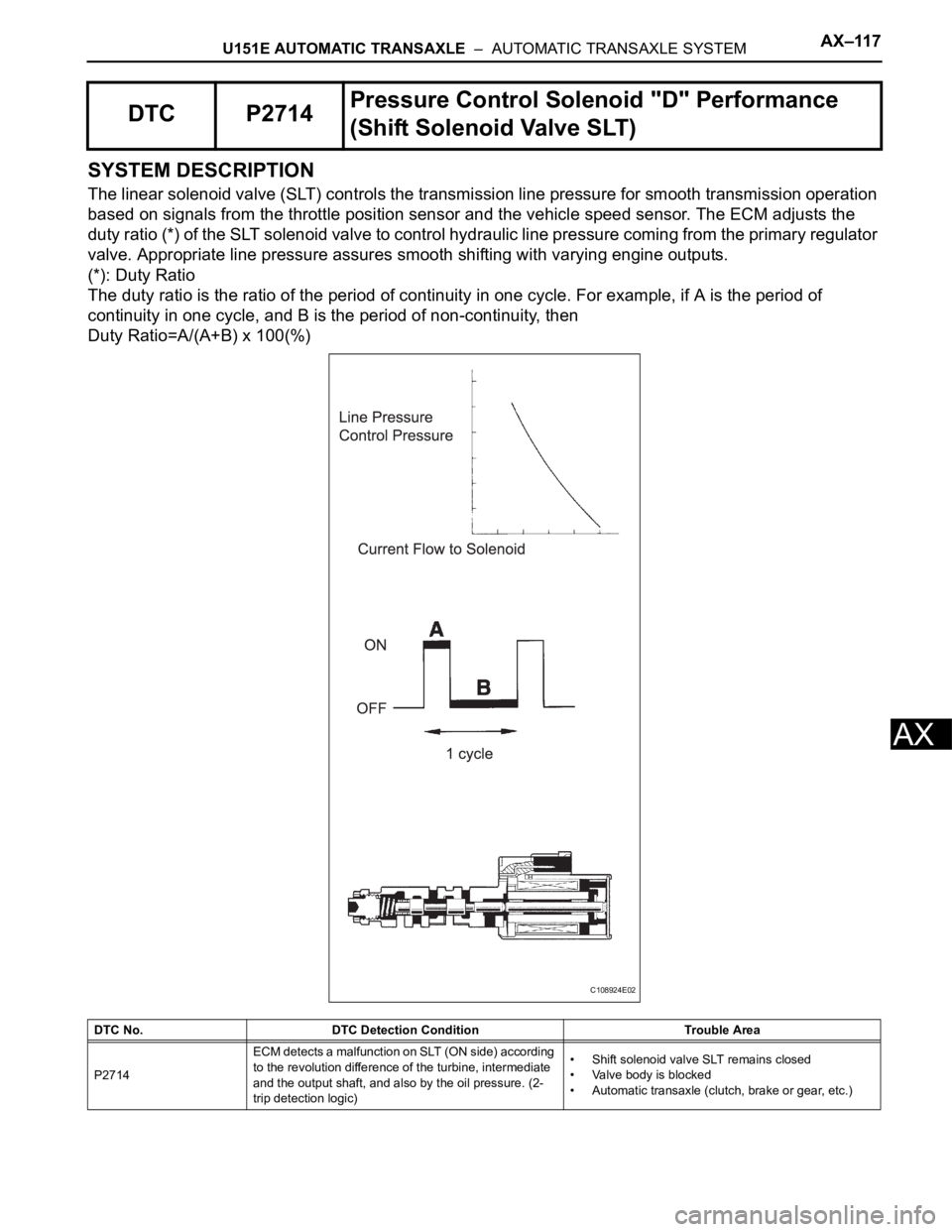
The linear solenoid valve (SLT) controls the transmission line pressure for smooth transmission operation
based on signals from the throttle position sensor and the vehicle speed sensor. The ECM adjusts the
duty ratio (*) of the SLT solenoid valve to control hydraulic line pressure coming from the primary regulator
valve. Appropriate line pressure assures smooth shifting with varying engine outputs.
(*): Duty Ratio
The duty ratio is the ratio of the period of continuity in one cycle. For example, if A is the period of
continuity in one cycle, and B is the period of non-continuity, then
Duty Ratio=A/(A+B) x 100(%)
DTC P2714Pressure Control Solenoid "D" Performance
(Shift Solenoid Valve SLT)
DTC No. DTC Detection Condition Trouble Area
P2714ECM detects a malfunction on SLT (ON side) according
to the revolution difference of the turbine, intermediate
and the output shaft, and also by the oil pressure. (2-
trip detection logic)• Shift solenoid valve SLT remains closed
• Valve body is blocked
• Automatic transaxle (clutch, brake or gear, etc.)
C108924E02
Page 1496 of 3000

AX–10U151E AUTOMATIC TRANSAXLE – AUTOMATIC TRANSAXLE SYSTEM
AX
ROAD TEST
1. PROBLEM SYMPTOM CONFIRMATION
(a) Based on the result of the customer problem
analysis, try to reproduce the symptoms. If the
problem is that the transaxle does not shift up, shift
down, or the shift point is too high or too low,
conduct the following road test referring to the
automatic shift schedule and simulate the problem
symptoms.
2. ROAD TEST
NOTICE:
Perform the test at the ATF temperature 50 to 80
C
(122 to 176
F) in the normal operation.
(a) D position test:
Shift into the D position and fully depress the
accelerator pedal and check the following points.
(1) Check up-shift operation.
Check that 1
2, 2 3, 3 4 and 4 5th up-
shifts take place, and that the shift points
conform to the automatic shift schedule (See
page SS-24).
HINT:
5th Gear Up-shift Prohibition Control
• Engine coolant temperature is 55
C (131F)
or less and vehicle speed is at 80 km/h (176
mph) or less.
• ATF temperature is -2
C (28F) or less.
4th Gear Up-shift Prohibition Control
• Coolant temperature is 47
C (117F) or less
and vehicle speed is at 55 km/h (34 mph) or
less.
5th and 4th Gear Lock-up Prohibition Control
• Brake pedal is depressed.
• Accelerator pedal is released.
• Coolant temperature is 60
C (140F) or less.
(2) Check for shift shock and slip.
Check for shock and slip at the 1
2, 2 3, 3
4 and 4 5th up-shifts.
(3) Check for abnormal noise and vibration.
Drive in the D position lock-up or 5th gear, and
check for abnormal noises and vibration.
HINT:
The check for the cause of abnormal noise and
vibration must be done very thoroughly as it
could also be due to loss of balance in the
differential, torque converter clutch, etc.
(4) Check kick-down operation.
Check that the possible kick-down vehicle speed
limits for 2nd to 1st, 3rd to 2nd, 4th to 3rd, 5th to
4th kick-downs conform to those indicated on
the automatic shift schedule while driving
through all gears with the shift lever in the D
position (See page SS-24).
(5) Check abnormal shock and slip at kick-down.