brake TOYOTA SIENNA 2007 Service Manual PDF
[x] Cancel search | Manufacturer: TOYOTA, Model Year: 2007, Model line: SIENNA, Model: TOYOTA SIENNA 2007Pages: 3000, PDF Size: 52.26 MB
Page 1538 of 3000
AX–150U151E AUTOMATIC TRANSAXLE – SHIFT LEVER
AX
ADJUSTMENT
1. INSPECT SHIFT LEVER POSITION
(a) When shifting from P to R position only with ignition
switch ON and brake pedal, make sure that the
shifting lever moves smoothly and can be
moderately operated.
(b) When starting engine, make sure that the vehicle
moves forward when shifting from N to D position
and moves rearward when shifting to R position.
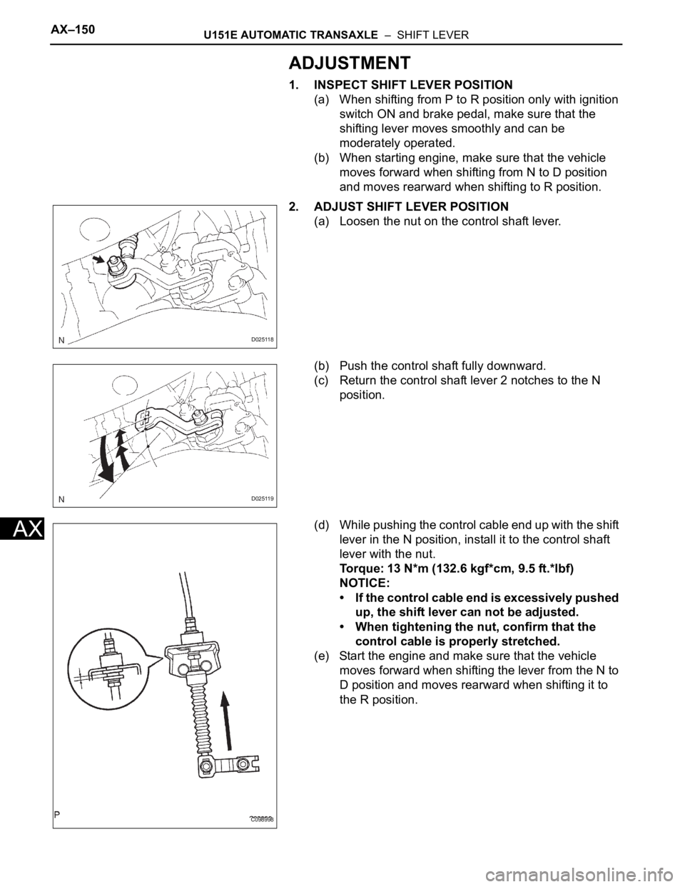
2. ADJUST SHIFT LEVER POSITION
(a) Loosen the nut on the control shaft lever.
(b) Push the control shaft fully downward.
(c) Return the control shaft lever 2 notches to the N
position.
(d) While pushing the control cable end up with the shift
lever in the N position, install it to the control shaft
lever with the nut.
Torque: 13 N*m (132.6 kgf*cm, 9.5 ft.*lbf)
NOTICE:
• If the control cable end is excessively pushed
up, the shift lever can not be adjusted.
• When tightening the nut, confirm that the
control cable is properly stretched.
(e) Start the engine and make sure that the vehicle
moves forward when shifting the lever from the N to
D position and moves rearward when shifting it to
the R position.
D025118
D025119
C098998
Page 1548 of 3000
AX–156U151E AUTOMATIC TRANSAXLE – TRANSMISSION CONTROL CABLE ASSEMBLY
AX
ADJUSTMENT
1. INSPECT SHIFT LEVER POSITION
(a) When shifting from P to R position only with ignition
switch ON and brake pedal, make sure that the
shifting lever moves smoothly and can be
moderately operated.
(b) When starting engine, make sure that the vehicle
moves forward when shifting from N to D position
and moves rearward when shifting to R position.
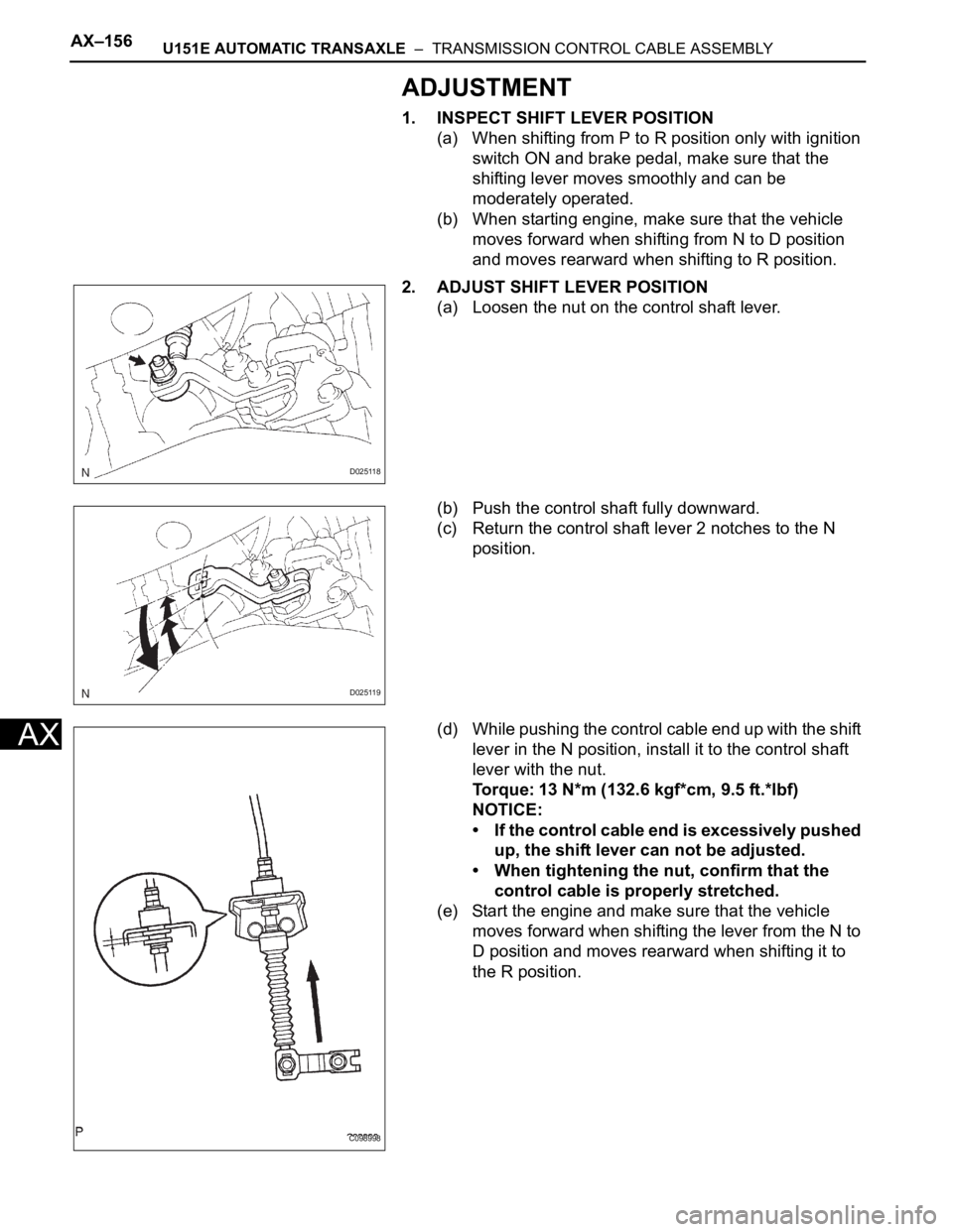
2. ADJUST SHIFT LEVER POSITION
(a) Loosen the nut on the control shaft lever.
(b) Push the control shaft fully downward.
(c) Return the control shaft lever 2 notches to the N
position.
(d) While pushing the control cable end up with the shift
lever in the N position, install it to the control shaft
lever with the nut.
Torque: 13 N*m (132.6 kgf*cm, 9.5 ft.*lbf)
NOTICE:
• If the control cable end is excessively pushed
up, the shift lever can not be adjusted.
• When tightening the nut, confirm that the
control cable is properly stretched.
(e) Start the engine and make sure that the vehicle
moves forward when shifting the lever from the N to
D position and moves rearward when shifting it to
the R position.
D025118
D025119
C098998
Page 1559 of 3000
AX–180U151E AUTOMATIC TRANSAXLE – AUTOMATIC TRANSAXLE UNIT
AX
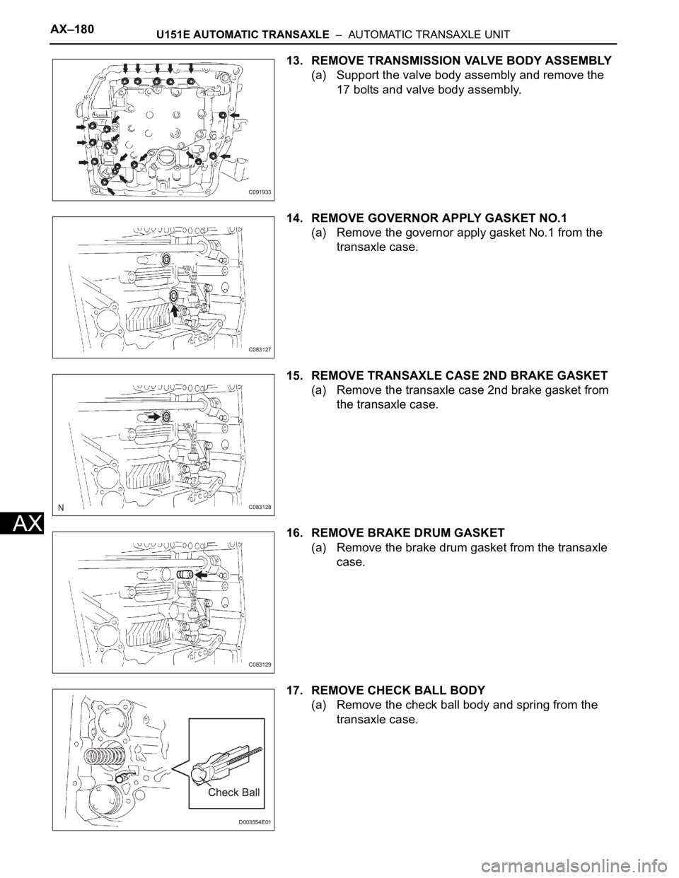
13. REMOVE TRANSMISSION VALVE BODY ASSEMBLY
(a) Support the valve body assembly and remove the
17 bolts and valve body assembly.
14. REMOVE GOVERNOR APPLY GASKET NO.1
(a) Remove the governor apply gasket No.1 from the
transaxle case.
15. REMOVE TRANSAXLE CASE 2ND BRAKE GASKET
(a) Remove the transaxle case 2nd brake gasket from
the transaxle case.
16. REMOVE BRAKE DRUM GASKET
(a) Remove the brake drum gasket from the transaxle
case.
17. REMOVE CHECK BALL BODY
(a) Remove the check ball body and spring from the
transaxle case.
C091933
C083127
C083128
C083129
D003554E01
Page 1564 of 3000

U151E AUTOMATIC TRANSAXLE – AUTOMATIC TRANSAXLE UNITAX–185
AX
33. REMOVE DIFFERENTIAL GEAR ASSEMBLY
(a) Remove the differential gear assembly from the
transaxle case.
34. REMOVE OVERDRIVE BRAKE GASKET
(a) Remove the 2 overdrive brake gaskets from the
transaxle case.
35. REMOVE FORWARD CLUTCH ASSEMBLY
(a) Remove the forward clutch assembly from the
transaxle case.
(b) Remove the thrust needle roller bearing from the
forward clutch.
36. REMOVE MULTIPLE DISC CLUTCH HUB
(a) Remove the thrust needle roller bearing, multiple
disc clutch hub, thrust needle roller bearing and
thrust bearing race No.1 from the transaxle case.
37. INSPECT MULTIPLE DISC CLUTCH CLUTCH HUB
HINT:
(See page AX-197)
D026450E04
D003573
D003574E02
D003906E01
D026787E03
Page 1568 of 3000
U151E AUTOMATIC TRANSAXLE – AUTOMATIC TRANSAXLE UNITAX–189
AX
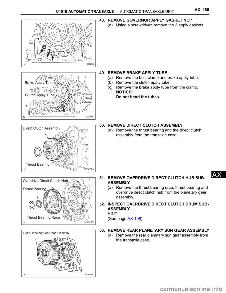
48. REMOVE GOVERNOR APPLY GASKET NO.1
(a) Using a screwdriver, remove the 3 apply gaskets.
49. REMOVE BRAKE APPLY TUBE
(a) Remove the bolt, clamp and brake apply tube.
(b) Remove the clutch apply tube.
(c) Remove the brake apply tube from the clamp.
NOTICE:
Do not bend the tubes.
50. REMOVE DIRECT CLUTCH ASSEMBLY
(a) Remove the thrust bearing and the direct clutch
assembly from the transaxle case.
51. REMOVE OVERDRIVE DIRECT CLUTCH HUB SUB-
ASSEMBLY
(a) Remove the thrust bearing race, thrust bearing and
overdrive direct clutch hub from the planetary gear
assembly.
52. INSPECT OVERDRIVE DIRECT CLUTCH DRUM SUB-
ASSEMBLY
HINT:
(See page AX-198)
53. REMOVE REAR PLANETARY SUN GEAR ASSEMBLY
(a) Remove the rear planetary sun gear assembly from
the transaxle case.
D026390
D026391E03
D026403E02
D026392E03
D026714E02
Page 1570 of 3000

U151E AUTOMATIC TRANSAXLE – AUTOMATIC TRANSAXLE UNITAX–191
AX
56. REMOVE PLANETARY CARRIER THRUST WASHER
NO.1
(a) Remove the planetary carrier thrust washer No.1
from the planetary gear assembly.
57. REMOVE 2ND BRAKE CLUTCH DISC
(a) Using a screwdriver, remove the snap ring.
(b) Remove the flange, 4 discs and 4 plates from the
transaxle case.
58. INSPECT 2ND BRAKE CLUTCH DISC
HINT:
(See page AX-198)
59. REMOVE 2ND BRAKE PISTON ASSEMBLY
(a) Using a screwdriver, remove the snap ring.
(b) Remove the 2ND brake piston assembly from the
transaxle case.
60. REMOVE REAR PLANETARY GEAR ASSEMBLY
(a) Using a screwdriver, remove the snap ring.
D026394E02
D026395E01
D008058E01
D026396E04
D003616E01
Page 1571 of 3000

AX–192U151E AUTOMATIC TRANSAXLE – AUTOMATIC TRANSAXLE UNIT
AX
(b) Remove the rear planetary gear assembly from the
transaxle case.
61. REMOVE INPUT SUN GEAR
(a) Remove the 2 thrust needle roller bearings, thrust
bearing race No.2 and the input sun gear from the
transaxle case.
62. REMOVE 1ST AND REVERSE BRAKE CLUTCH DISC
(a) Remove the flange, 6 discs and 6 plates from the
transaxle case.
63. INSPECT 1ST AND REVERSE BRAKE CLUTCH DISC
HINT:
(See page AX-198)
64. REMOVE FRONT PLANETARY GEAR ASSEMBLY
(a) Using a chisel and hammer, unstake the lock
washer.
NOTICE:
Push down all claws of the washer. Otherwise
the SST cannot be fully pressed against the nut,
and cannot loosen the nut.
(b) Using SST, remove the nut.
SST 09387-00030, 09387-00080
D026591E02
D003873E02
D026397
D003595E01
D003596E01
Page 1572 of 3000

U151E AUTOMATIC TRANSAXLE – AUTOMATIC TRANSAXLE UNITAX–193
AX
(c) Using SST and a press, remove the front planetary
gear assembly from the counter drive gear.
SST 09950-60010 (09951-00450), 09950-70010
(09951-07100)
(d) Remove the front planetary gear assembly from the
brake hub.
65. REMOVE FRONT PLANETARY RING GEAR
(a) Using a screwdriver, remove the snap ring and front
planetary ring gear from the brake hub.
66. REMOVE 1ST AND REVERSE BRAKE RETURN
SPRING SUB-ASSEMBLY
(a) Place SST on the return spring, and compress the
return spring with a press.
SST 09387-00070
(b) Using a snap ring expander, remove the snap ring.
NOTICE:
• Stop the press when the spring seat is
lowered 1 to 2 mm (0.039 to 0.078 in.) from the
snap ring groove, to prevent the spring seat
from being deformed.
• Do not expand the snap ring excessively.
67. INSPECT 1ST AND REVERSE BRAKE RETURN
SPRING SUB-ASSEMBLY
HINT:
(See page AX-198)
D026398E01
D026763E01
D003615E02
D003600E01
Page 1573 of 3000

AX–194U151E AUTOMATIC TRANSAXLE – AUTOMATIC TRANSAXLE UNIT
AX
68. REMOVE 1ST AND REVERSE BRAKE PISTON
(a) Apply compressed air (392 kPa, 4.0 kgf/cm
2, 57 psi)
to the transaxle case to remove the 1st and reverse
brake piston.
NOTICE:
• Applying compressed air may cause the
piston to jump-out. When removing the
piston, hold it using a waste cloth.
• Take care not to splash ATF when applying
compressed air.
(b) Remove the 2 O-rings from the 1st and reverse
brake piston.
69. REMOVE COUNTER DRIVE GEAR
(a) Using SST and a press, remove the counter drive
gear from the transaxle case.
SST 09950-60010 (09951-00590), 09950-70010
(09951-07100)
(b) As shown in the illustration, tighten the 2 bolts
evenly and make clearance of approx. 20.0 mm
(0.787 in.) between the counter drive gear and the
inner race.
(c) Using SST, remove the tapered roller bearing.
SST 09950-60010 (09951-00590), 09950-00020,
09950-00030, 09950-40011 (09957-04010)
D026405E01
D026713E01
C089120E01
D003602E01
D003603E01
Page 1574 of 3000

U151E AUTOMATIC TRANSAXLE – AUTOMATIC TRANSAXLE UNITAX–195
AX
70. REMOVE TRANSFER DRIVEN PINION FRONT
BEARING
(a) Using a snap ring expander, remove the snap ring.
(b) Using SST and a press, remove the bearing outer
race.
SST 09950-60020 (09951-00910)
71. REMOVE BREATHER PLUG NO.2 (ATM)
72. REMOVE UNDERDRIVE BRAKE RETURN SPRING
SUB-ASSEMBLY
(a) Place SST on the return spring, and compress the
return spring with a press.
SST 09387-00020
(b) Using a snap ring expander, remove the snap ring.
NOTICE:
• Stop the press when the spring seat is
lowered 1 to 2 mm (0.039 to 0.078 in.) from the
snap ring groove, to prevent the spring seat
from being deformed.
• Do not expand the snap ring excessively.
73. INSPECT UNDERDRIVE BRAKE RETURN SPRING
SUB-ASSEMBLY
HINT:
(See page AX-199)
74. REMOVE UNDERDRIVE BRAKE PISTON
(a) Apply compressed air (392 kPa, 4.0 kgf/cm
2, 57 psi)
to the transaxle case to remove the underdrive
brake piston.
D026467E01
C089121E01
D026407E01
D026406E01