TOYOTA SIENNA 2007 Service Repair Manual
Manufacturer: TOYOTA, Model Year: 2007, Model line: SIENNA, Model: TOYOTA SIENNA 2007Pages: 3000, PDF Size: 52.26 MB
Page 981 of 3000
2GR-FE ENGINE MECHANICAL – DRIVE BELTEM–7
EM
INSTALLATION
1. INSTALL V-RIBBED BELT
(a) Install the V-ribbed belt.
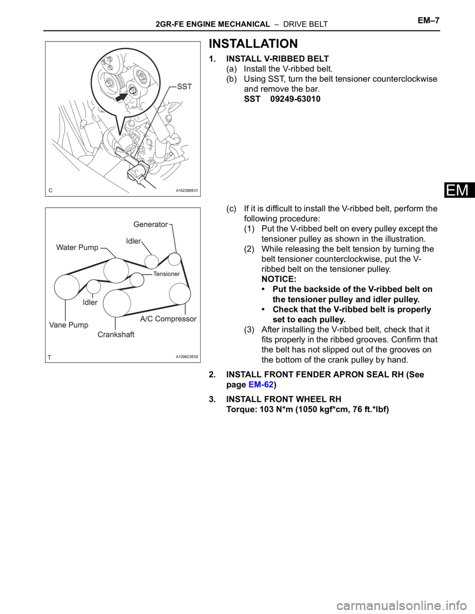
(b) Using SST, turn the belt tensioner counterclockwise
and remove the bar.
SST 09249-63010
(c) If it is difficult to install the V-ribbed belt, perform the
following procedure:
(1) Put the V-ribbed belt on every pulley except the
tensioner pulley as shown in the illustration.
(2) While releasing the belt tension by turning the
belt tensioner counterclockwise, put the V-
ribbed belt on the tensioner pulley.
NOTICE:
• Put the backside of the V-ribbed belt on
the tensioner pulley and idler pulley.
• Check that the V-ribbed belt is properly
set to each pulley.
(3) After installing the V-ribbed belt, check that it
fits properly in the ribbed grooves. Confirm that
the belt has not slipped out of the grooves on
the bottom of the crank pulley by hand.
2. INSTALL FRONT FENDER APRON SEAL RH (See
page EM-62)
3. INSTALL FRONT WHEEL RH
Torque: 103 N*m (1050 kgf*cm, 76 ft.*lbf)
A162386E01
A129623E02
Page 982 of 3000
2GR-FE ENGINE MECHANICAL – ENGINE REAR OIL SEALEM–11
EM
ENGINE
2GR-FE ENGINE MECHANICAL
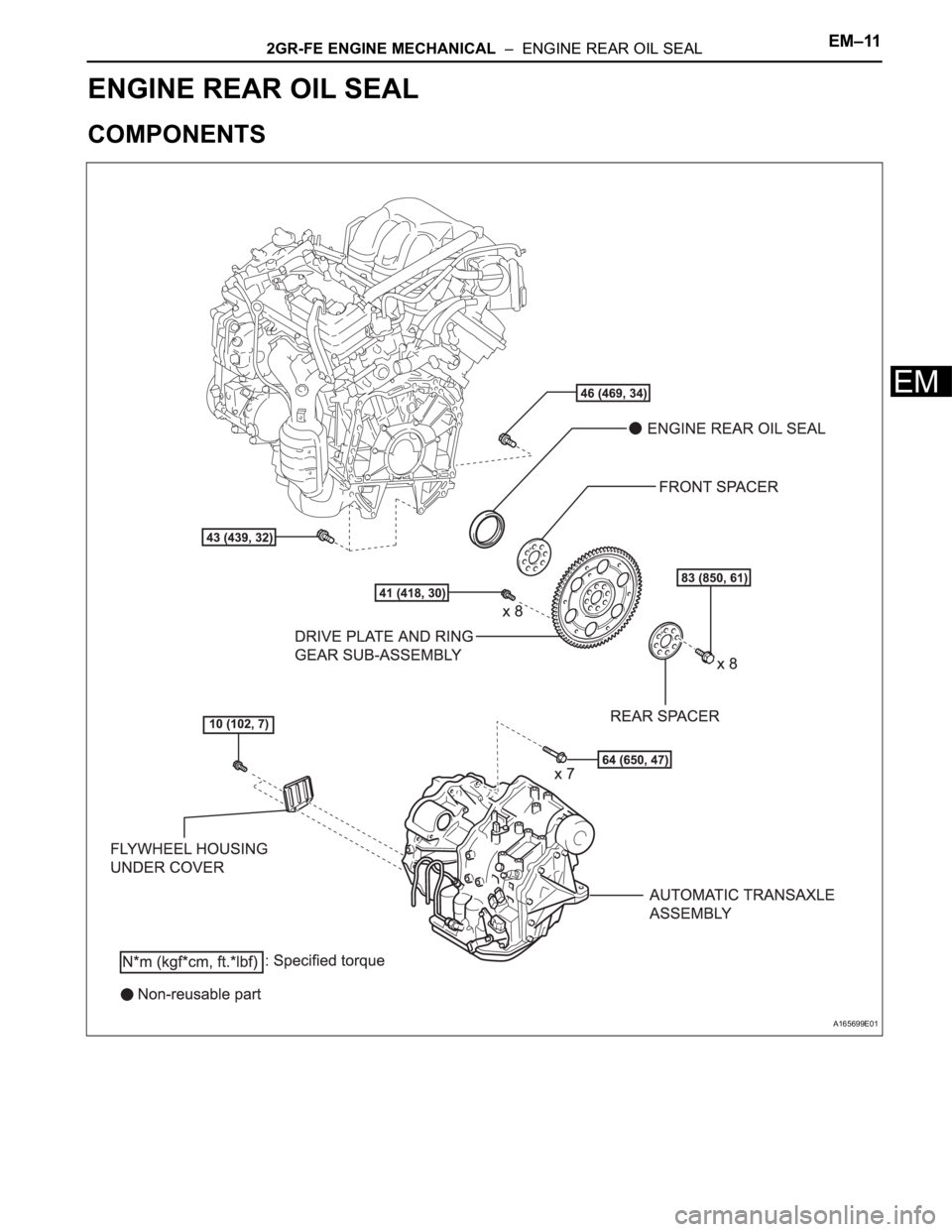
ENGINE REAR OIL SEAL
COMPONENTS
A165699E01
Page 983 of 3000
EM–122GR-FE ENGINE MECHANICAL – ENGINE REAR OIL SEAL
EM
REMOVAL
1. REMOVE AUTOMATIC TRANSAXLE ASSEMBLY (for
2WD)
HINT:
See page AX-163.
2. REMOVE AUTOMATIC TRANSAXLE ASSEMBLY (for
4WD)
HINT:
See page AX-167.
3. REMOVE DRIVE PLATE AND RING GEAR SUB-
ASSEMBLY
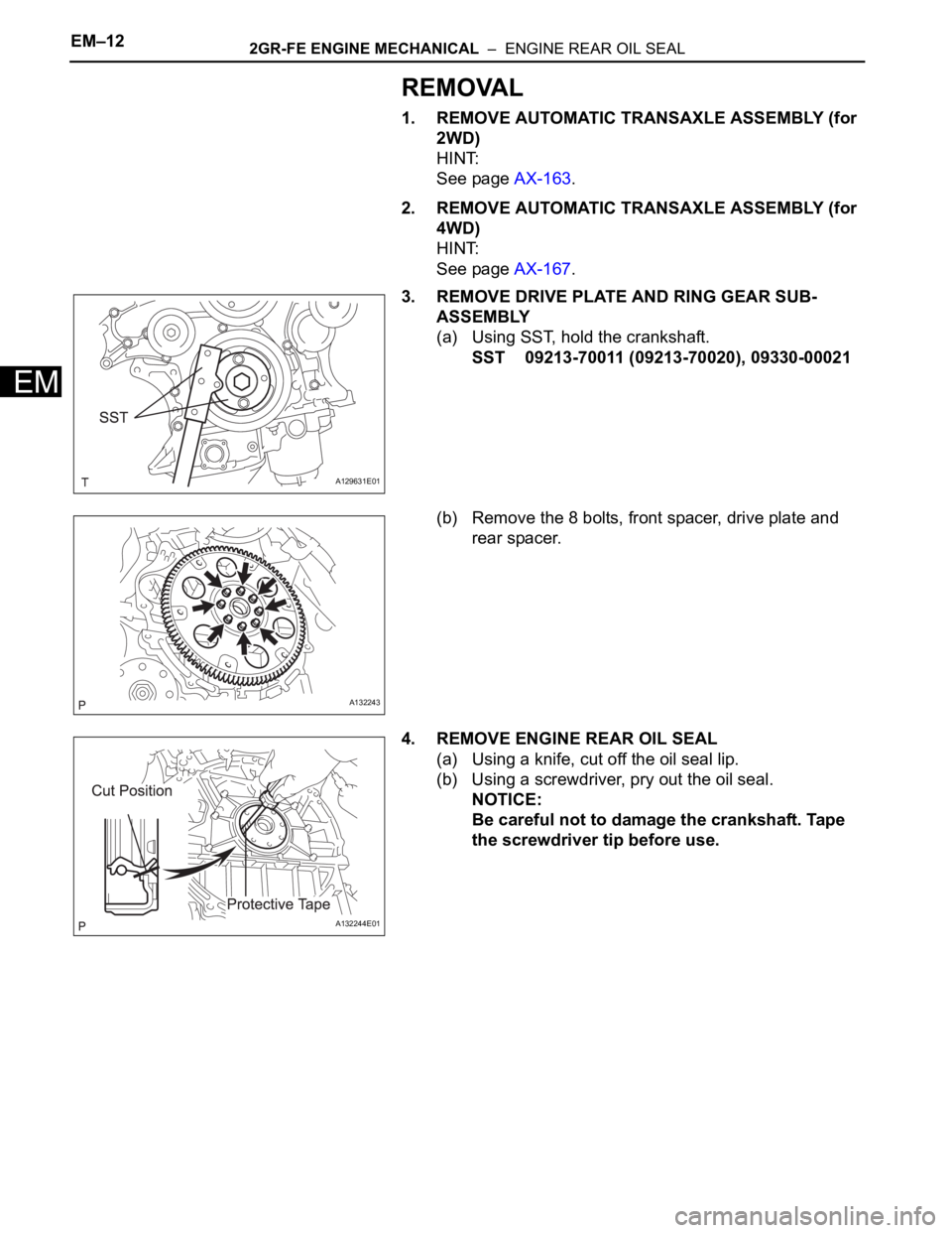
(a) Using SST, hold the crankshaft.
SST 09213-70011 (09213-70020), 09330-00021
(b) Remove the 8 bolts, front spacer, drive plate and
rear spacer.
4. REMOVE ENGINE REAR OIL SEAL
(a) Using a knife, cut off the oil seal lip.
(b) Using a screwdriver, pry out the oil seal.
NOTICE:
Be careful not to damage the crankshaft. Tape
the screwdriver tip before use.
A129631E01
A132243
A132244E01
Page 984 of 3000
2GR-FE ENGINE MECHANICAL – ENGINE REAR OIL SEALEM–13
EM
INSTALLATION
1. INSTALL ENGINE REAR OIL SEAL
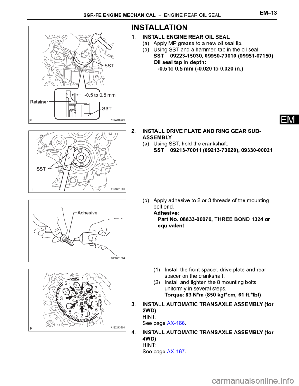
(a) Apply MP grease to a new oil seal lip.
(b) Using SST and a hammer, tap in the oil seal.
SST 09223-15030, 09950-70010 (09951-07150)
Oil seal tap in depth:
-0.5 to 0.5 mm (-0.020 to 0.020 in.)
2. INSTALL DRIVE PLATE AND RING GEAR SUB-
ASSEMBLY
(a) Using SST, hold the crankshaft.
SST 09213-70011 (09213-70020), 09330-00021
(b) Apply adhesive to 2 or 3 threads of the mounting
bolt end.
Adhesive:
Part No. 08833-00070, THREE BOND 1324 or
equivalent
(1) Install the front spacer, drive plate and rear
spacer on the crankshaft.
(2) Install and tighten the 8 mounting bolts
uniformly in several steps.
Torque: 83 N*m (850 kgf*cm, 61 ft.*lbf)
3. INSTALL AUTOMATIC TRANSAXLE ASSEMBLY (for
2WD)
HINT:
See page AX-166.
4. INSTALL AUTOMATIC TRANSAXLE ASSEMBLY (for
4WD)
HINT:
See page AX-167.
A132245E01
A129631E01
P000601E04
A132243E01
Page 985 of 3000
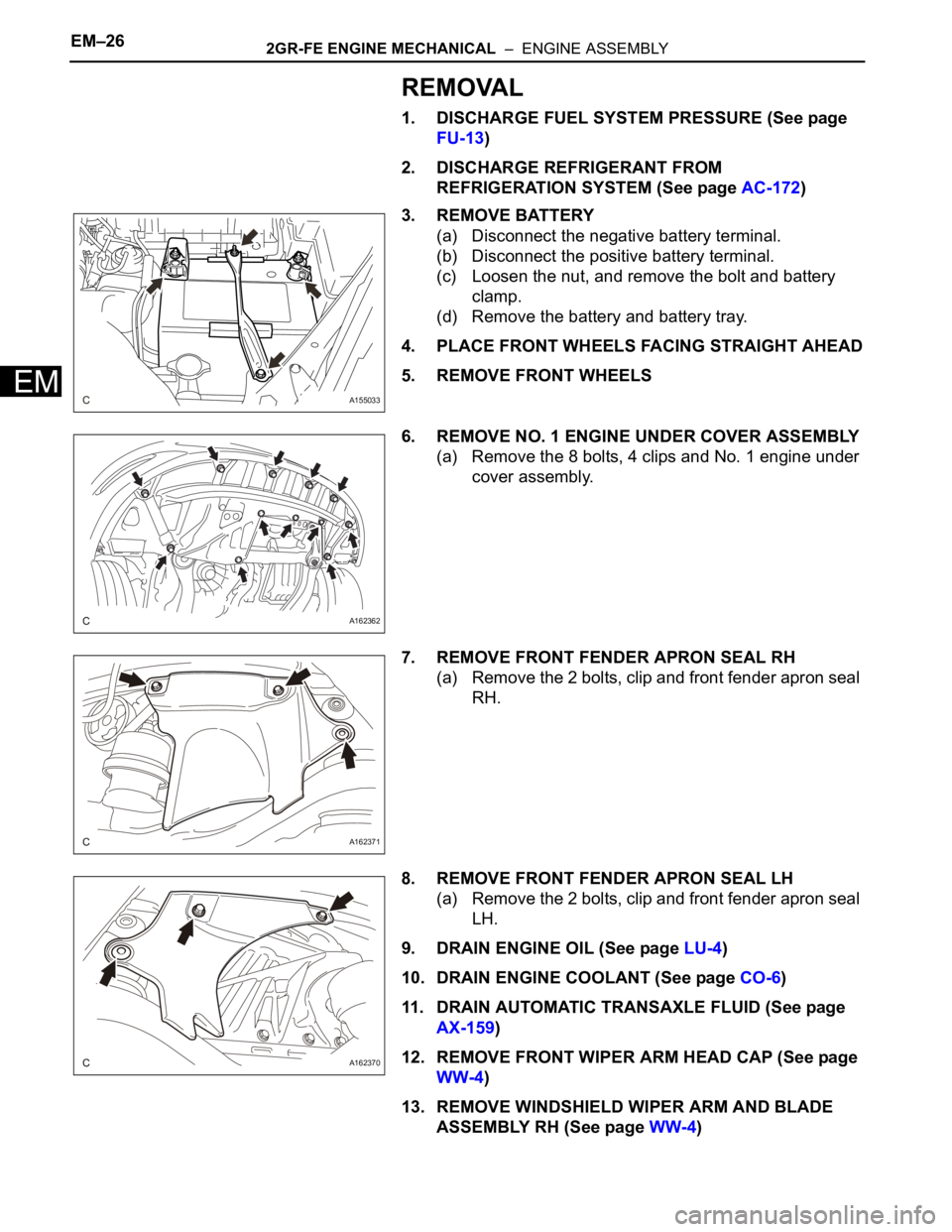
EM–262GR-FE ENGINE MECHANICAL – ENGINE ASSEMBLY
EM
REMOVAL
1. DISCHARGE FUEL SYSTEM PRESSURE (See page
FU-13)
2. DISCHARGE REFRIGERANT FROM
REFRIGERATION SYSTEM (See page AC-172)
3. REMOVE BATTERY
(a) Disconnect the negative battery terminal.
(b) Disconnect the positive battery terminal.
(c) Loosen the nut, and remove the bolt and battery
clamp.
(d) Remove the battery and battery tray.
4. PLACE FRONT WHEELS FACING STRAIGHT AHEAD
5. REMOVE FRONT WHEELS
6. REMOVE NO. 1 ENGINE UNDER COVER ASSEMBLY
(a) Remove the 8 bolts, 4 clips and No. 1 engine under
cover assembly.
7. REMOVE FRONT FENDER APRON SEAL RH
(a) Remove the 2 bolts, clip and front fender apron seal
RH.
8. REMOVE FRONT FENDER APRON SEAL LH
(a) Remove the 2 bolts, clip and front fender apron seal
LH.
9. DRAIN ENGINE OIL (See page LU-4)
10. DRAIN ENGINE COOLANT (See page CO-6)
11. DRAIN AUTOMATIC TRANSAXLE FLUID (See page
AX-159)
12. REMOVE FRONT WIPER ARM HEAD CAP (See page
WW-4)
13. REMOVE WINDSHIELD WIPER ARM AND BLADE
ASSEMBLY RH (See page WW-4)
A155033
A162362
A162371
A162370
Page 986 of 3000
2GR-FE ENGINE MECHANICAL – ENGINE ASSEMBLYEM–27
EM
14. REMOVE WINDSHIELD WIPER ARM AND BLADE
ASSEMBLY LH (See page WW-4)
15. REMOVE COWL TOP VENTILATOR LOUVER SUB-
ASSEMBLY (See page WW-4)
16. REMOVE FRONT WIPER MOTOR AND LINK
ASSEMBLY (See page WW-4)
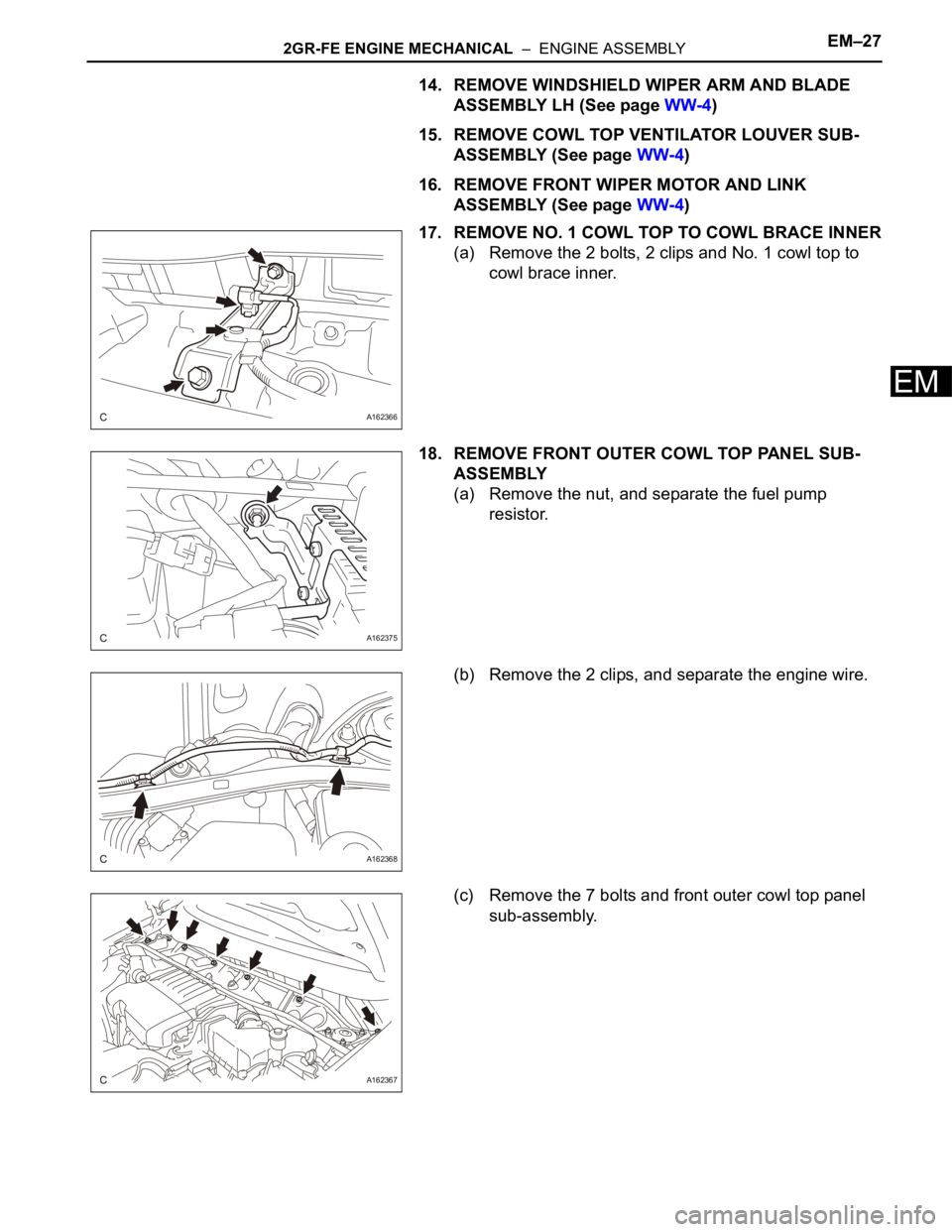
17. REMOVE NO. 1 COWL TOP TO COWL BRACE INNER
(a) Remove the 2 bolts, 2 clips and No. 1 cowl top to
cowl brace inner.
18. REMOVE FRONT OUTER COWL TOP PANEL SUB-
ASSEMBLY
(a) Remove the nut, and separate the fuel pump
resistor.
(b) Remove the 2 clips, and separate the engine wire.
(c) Remove the 7 bolts and front outer cowl top panel
sub-assembly.
A162366
A162375
A162368
A162367
Page 987 of 3000
EM–282GR-FE ENGINE MECHANICAL – ENGINE ASSEMBLY
EM
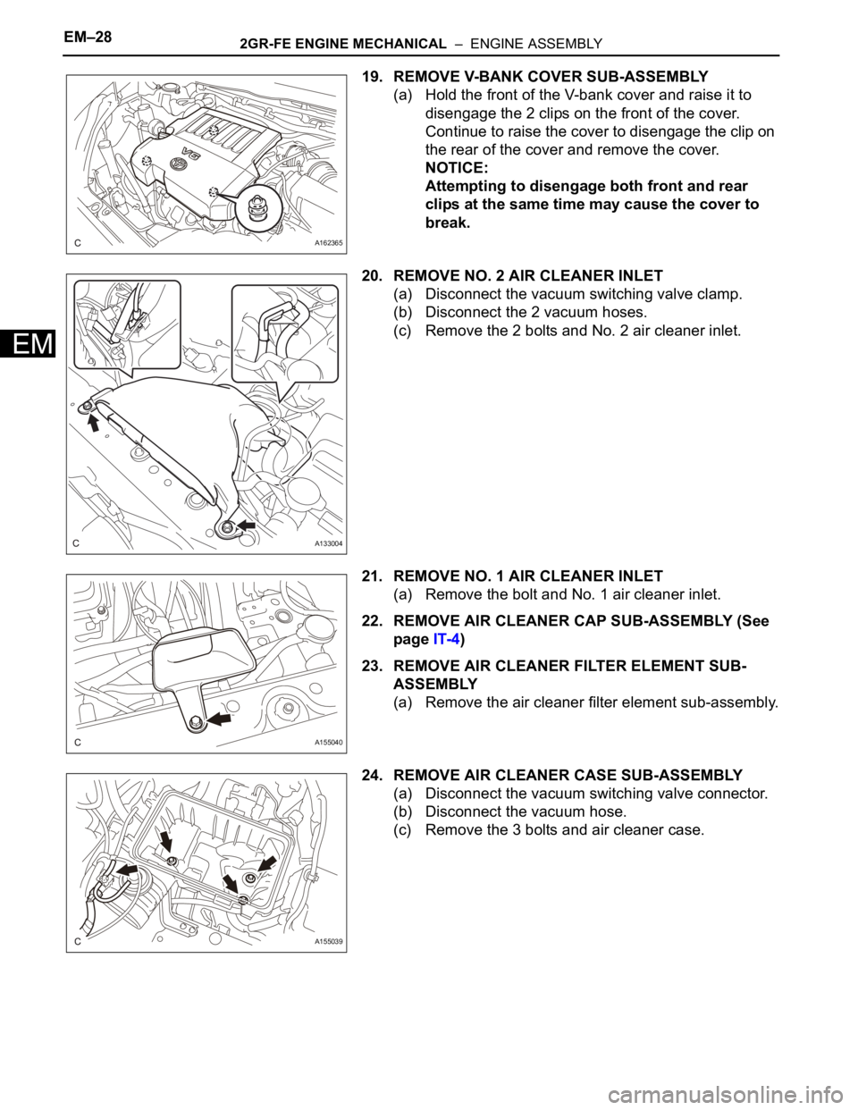
19. REMOVE V-BANK COVER SUB-ASSEMBLY
(a) Hold the front of the V-bank cover and raise it to
disengage the 2 clips on the front of the cover.
Continue to raise the cover to disengage the clip on
the rear of the cover and remove the cover.
NOTICE:
Attempting to disengage both front and rear
clips at the same time may cause the cover to
break.
20. REMOVE NO. 2 AIR CLEANER INLET
(a) Disconnect the vacuum switching valve clamp.
(b) Disconnect the 2 vacuum hoses.
(c) Remove the 2 bolts and No. 2 air cleaner inlet.
21. REMOVE NO. 1 AIR CLEANER INLET
(a) Remove the bolt and No. 1 air cleaner inlet.
22. REMOVE AIR CLEANER CAP SUB-ASSEMBLY (See
page IT-4)
23. REMOVE AIR CLEANER FILTER ELEMENT SUB-
ASSEMBLY
(a) Remove the air cleaner filter element sub-assembly.
24. REMOVE AIR CLEANER CASE SUB-ASSEMBLY
(a) Disconnect the vacuum switching valve connector.
(b) Disconnect the vacuum hose.
(c) Remove the 3 bolts and air cleaner case.
A162365
A133004
A155040
A155039
Page 988 of 3000
2GR-FE ENGINE MECHANICAL – ENGINE ASSEMBLYEM–29
EM
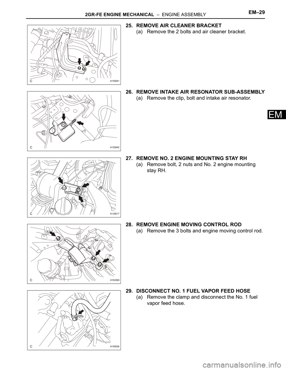
25. REMOVE AIR CLEANER BRACKET
(a) Remove the 2 bolts and air cleaner bracket.
26. REMOVE INTAKE AIR RESONATOR SUB-ASSEMBLY
(a) Remove the clip, bolt and intake air resonator.
27. REMOVE NO. 2 ENGINE MOUNTING STAY RH
(a) Remove bolt, 2 nuts and No. 2 engine mounting
stay RH.
28. REMOVE ENGINE MOVING CONTROL ROD
(a) Remove the 3 bolts and engine moving control rod.
29. DISCONNECT NO. 1 FUEL VAPOR FEED HOSE
(a) Remove the clamp and disconnect the No. 1 fuel
vapor feed hose.
A155041
A155042
A139217
A162369
A155036
Page 989 of 3000
EM–302GR-FE ENGINE MECHANICAL – ENGINE ASSEMBLY
EM
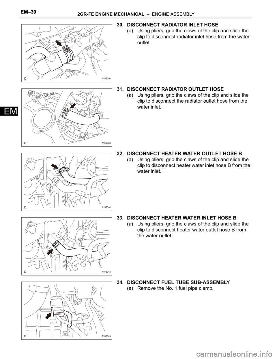
30. DISCONNECT RADIATOR INLET HOSE
(a) Using pliers, grip the claws of the clip and slide the
clip to disconnect radiator inlet hose from the water
outlet.
31. DISCONNECT RADIATOR OUTLET HOSE
(a) Using pliers, grip the claws of the clip and slide the
clip to disconnect the radiator outlet hose from the
water inlet.
32. DISCONNECT HEATER WATER OUTLET HOSE B
(a) Using pliers, grip the claws of the clip and slide the
clip to disconnect heater water inlet hose B from the
water inlet.
33. DISCONNECT HEATER WATER INLET HOSE B
(a) Using pliers, grip the claws of the clip and slide the
clip to disconnect heater water outlet hose B from
the water outlet.
34. DISCONNECT FUEL TUBE SUB-ASSEMBLY
(a) Remove the No. 1 fuel pipe clamp.
A155046
A155038
A155044
A155043
A155045
Page 990 of 3000
2GR-FE ENGINE MECHANICAL – ENGINE ASSEMBLYEM–31
EM
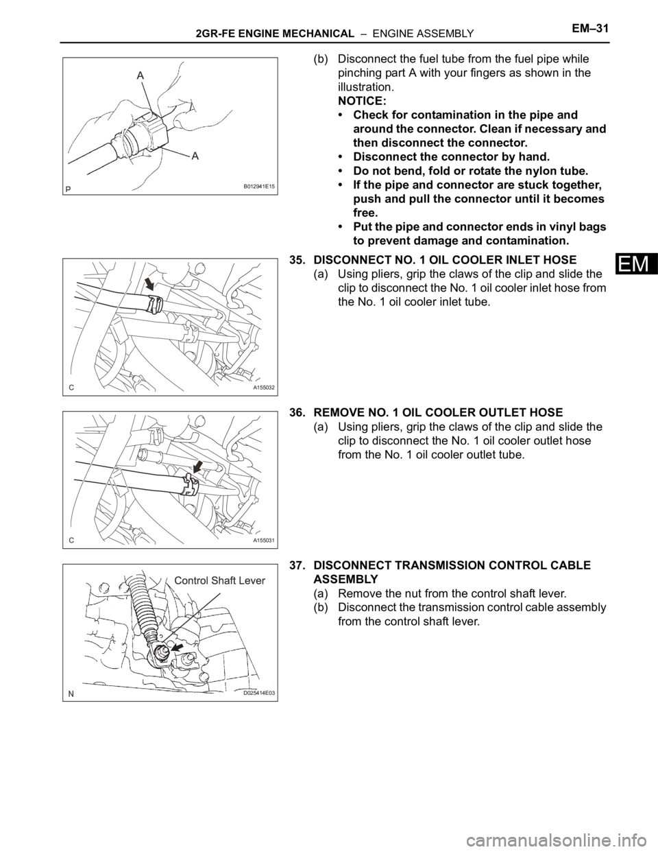
(b) Disconnect the fuel tube from the fuel pipe while
pinching part A with your fingers as shown in the
illustration.
NOTICE:
• Check for contamination in the pipe and
around the connector. Clean if necessary and
then disconnect the connector.
• Disconnect the connector by hand.
• Do not bend, fold or rotate the nylon tube.
• If the pipe and connector are stuck together,
push and pull the connector until it becomes
free.
• Put the pipe and connector ends in vinyl bags
to prevent damage and contamination.
35. DISCONNECT NO. 1 OIL COOLER INLET HOSE
(a) Using pliers, grip the claws of the clip and slide the
clip to disconnect the No. 1 oil cooler inlet hose from
the No. 1 oil cooler inlet tube.
36. REMOVE NO. 1 OIL COOLER OUTLET HOSE
(a) Using pliers, grip the claws of the clip and slide the
clip to disconnect the No. 1 oil cooler outlet hose
from the No. 1 oil cooler outlet tube.
37. DISCONNECT TRANSMISSION CONTROL CABLE
ASSEMBLY
(a) Remove the nut from the control shaft lever.
(b) Disconnect the transmission control cable assembly
from the control shaft lever.
B012941E15
A155032
A155031
D025414E03