TOYOTA SIENNA 2007 Service Repair Manual
Manufacturer: TOYOTA, Model Year: 2007, Model line: SIENNA, Model: TOYOTA SIENNA 2007Pages: 3000, PDF Size: 52.26 MB
Page 1011 of 3000
EM–522GR-FE ENGINE MECHANICAL – ENGINE ASSEMBLY
EM
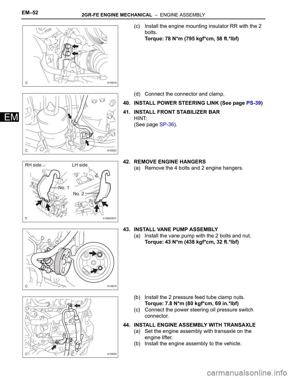
(c) Install the engine mounting insulator RR with the 2
bolts.
Torque: 78 N*m (795 kgf*cm, 58 ft.*lbf)
(d) Connect the connector and clamp.
40. INSTALL POWER STEERING LINK (See page PS-39)
41. INSTALL FRONT STABILIZER BAR
HINT:
(See page SP-36).
42. REMOVE ENGINE HANGERS
(a) Remove the 4 bolts and 2 engine hangers.
43. INSTALL VANE PUMP ASSEMBLY
(a) Install the vane pump with the 2 bolts and nut.
Torque: 43 N*m (438 kgf*cm, 32 ft.*lbf)
(b) Install the 2 pressure feed tube clamp nuts.
Torque: 7.8 N*m (80 kgf*cm, 69 in.*lbf)
(c) Connect the power steering oil pressure switch
connector.
44. INSTALL ENGINE ASSEMBLY WITH TRANSAXLE
(a) Set the engine assembly with transaxle on the
engine lifter.
(b) Install the engine assembly to the vehicle.
A155018
A155022
A129635E01
A139216
A155024
Page 1012 of 3000
2GR-FE ENGINE MECHANICAL – ENGINE ASSEMBLYEM–53
EM
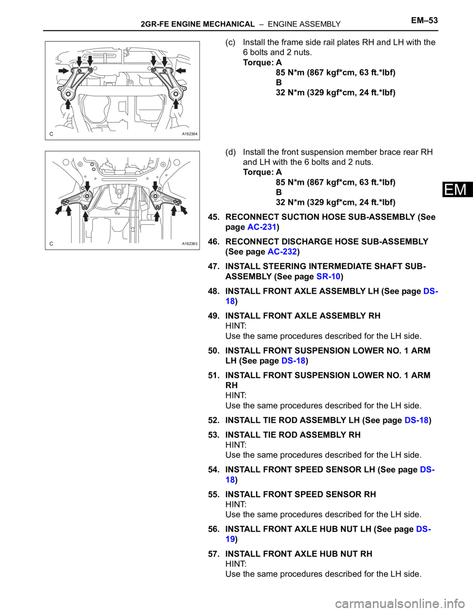
(c) Install the frame side rail plates RH and LH with the
6 bolts and 2 nuts.
Torque: A
85 N*m (867 kgf*cm, 63 ft.*lbf)
B
32 N*m (329 kgf*cm, 24 ft.*lbf)
(d) Install the front suspension member brace rear RH
and LH with the 6 bolts and 2 nuts.
Torque: A
85 N*m (867 kgf*cm, 63 ft.*lbf)
B
32 N*m (329 kgf*cm, 24 ft.*lbf)
45. RECONNECT SUCTION HOSE SUB-ASSEMBLY (See
page AC-231)
46. RECONNECT DISCHARGE HOSE SUB-ASSEMBLY
(See page AC-232)
47. INSTALL STEERING INTERMEDIATE SHAFT SUB-
ASSEMBLY (See page SR-10)
48. INSTALL FRONT AXLE ASSEMBLY LH (See page DS-
18)
49. INSTALL FRONT AXLE ASSEMBLY RH
HINT:
Use the same procedures described for the LH side.
50. INSTALL FRONT SUSPENSION LOWER NO. 1 ARM
LH (See page DS-18)
51. INSTALL FRONT SUSPENSION LOWER NO. 1 ARM
RH
HINT:
Use the same procedures described for the LH side.
52. INSTALL TIE ROD ASSEMBLY LH (See page DS-18)
53. INSTALL TIE ROD ASSEMBLY RH
HINT:
Use the same procedures described for the LH side.
54. INSTALL FRONT SPEED SENSOR LH (See page DS-
18)
55. INSTALL FRONT SPEED SENSOR RH
HINT:
Use the same procedures described for the LH side.
56. INSTALL FRONT AXLE HUB NUT LH (See page DS-
19)
57. INSTALL FRONT AXLE HUB NUT RH
HINT:
Use the same procedures described for the LH side.
A162364
A162363
Page 1013 of 3000
EM–542GR-FE ENGINE MECHANICAL – ENGINE ASSEMBLY
EM
58. INSTALL FRONT STABILIZER LINK ASSEMBLY LH
(See page DS-19)
59. INSTALL FRONT STABILIZER LINK ASSEMBLY RH
HINT:
Use the same procedures described for the LH side.
60. INSTALL PROPELLER WITH CENTER BEARING
SHAFT ASSEMBLY (See page PR-9)
61. FULLY TIGHTEN PROPELLER WITH CENTER
BEARING SHAFT ASSEMBLY (See page PR-10)
62. INSTALL FRONT EXHAUST PIPE ASSEMBLY (for
2WD)
(a) Install the front exhaust pipe assembly (See page
EX-4).
63. INSTALL FRONT EXHAUST PIPE ASSEMBLY (for
4WD)
(a) Install front exhaust pipe assembly (See page EX-
10).
64. INSTALL CENTER EXHAUST PIPE ASSEMBLY
(a) Install center exhaust pipe assembly (See page EX-
10).
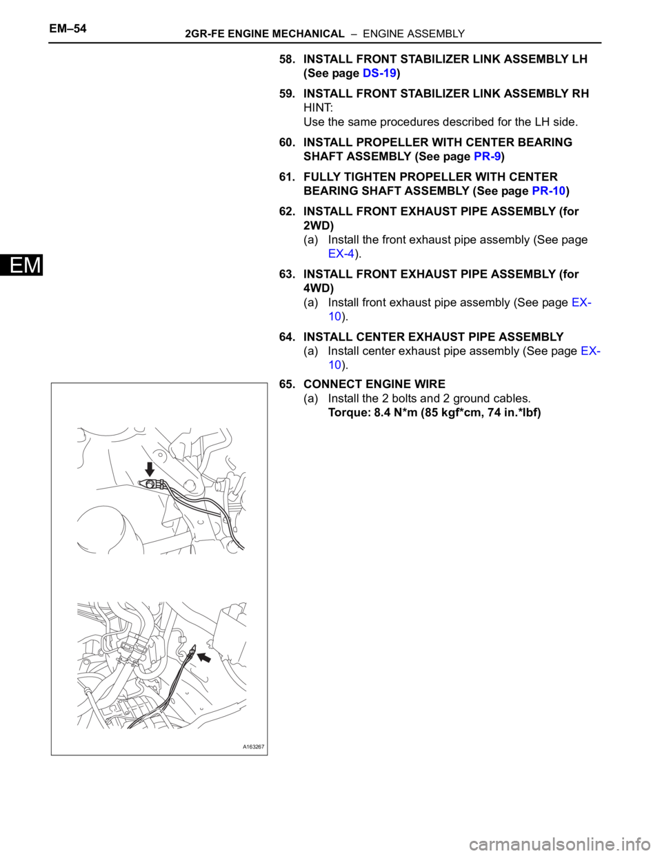
65. CONNECT ENGINE WIRE
(a) Install the 2 bolts and 2 ground cables.
Torque: 8.4 N*m (85 kgf*cm, 74 in.*lbf)
A163267
Page 1014 of 3000
2GR-FE ENGINE MECHANICAL – ENGINE ASSEMBLYEM–55
EM
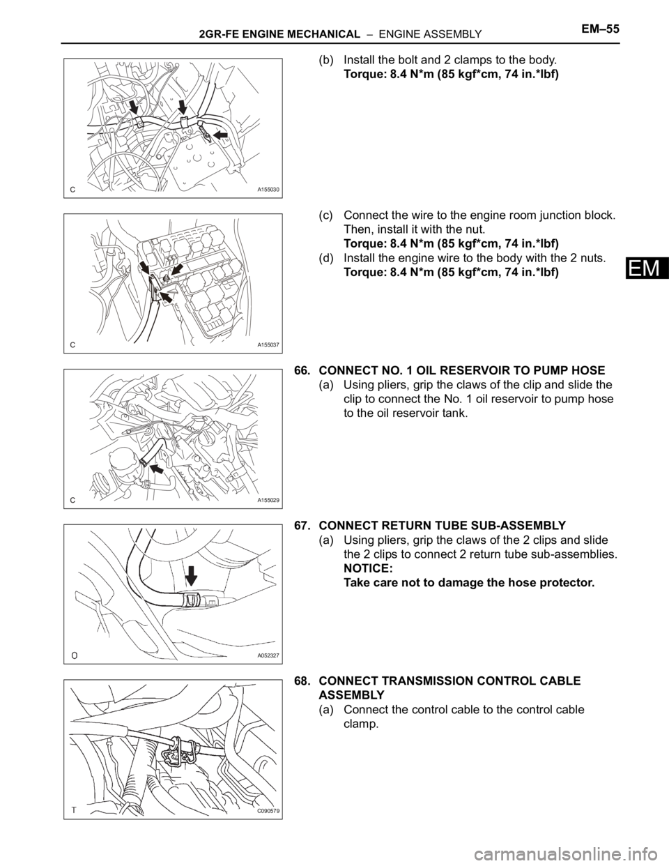
(b) Install the bolt and 2 clamps to the body.
Torque: 8.4 N*m (85 kgf*cm, 74 in.*lbf)
(c) Connect the wire to the engine room junction block.
Then, install it with the nut.
Torque: 8.4 N*m (85 kgf*cm, 74 in.*lbf)
(d) Install the engine wire to the body with the 2 nuts.
Torque: 8.4 N*m (85 kgf*cm, 74 in.*lbf)
66. CONNECT NO. 1 OIL RESERVOIR TO PUMP HOSE
(a) Using pliers, grip the claws of the clip and slide the
clip to connect the No. 1 oil reservoir to pump hose
to the oil reservoir tank.
67. CONNECT RETURN TUBE SUB-ASSEMBLY
(a) Using pliers, grip the claws of the 2 clips and slide
the 2 clips to connect 2 return tube sub-assemblies.
NOTICE:
Take care not to damage the hose protector.
68. CONNECT TRANSMISSION CONTROL CABLE
ASSEMBLY
(a) Connect the control cable to the control cable
clamp.
A155030
A155037
A155029
A052327
C090579
Page 1015 of 3000
EM–562GR-FE ENGINE MECHANICAL – ENGINE ASSEMBLY
EM
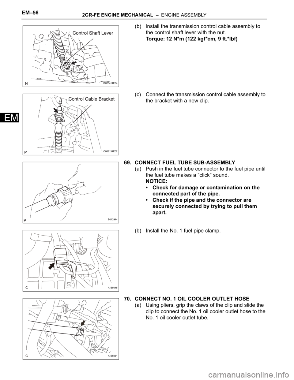
(b) Install the transmission control cable assembly to
the control shaft lever with the nut.
Torque: 12 N*m (122 kgf*cm, 9 ft.*lbf)
(c) Connect the transmission control cable assembly to
the bracket with a new clip.
69. CONNECT FUEL TUBE SUB-ASSEMBLY
(a) Push in the fuel tube connector to the fuel pipe until
the fuel tube makes a "click" sound.
NOTICE:
• Check for damage or contamination on the
connected part of the pipe.
• Check if the pipe and the connector are
securely connected by trying to pull them
apart.
(b) Install the No. 1 fuel pipe clamp.
70. CONNECT NO. 1 OIL COOLER OUTLET HOSE
(a) Using pliers, grip the claws of the clip and slide the
clip to connect the No. 1 oil cooler outlet hose to the
No. 1 oil cooler outlet tube.
D025414E04
C089134E02
B012944
A155045
A155031
Page 1016 of 3000
2GR-FE ENGINE MECHANICAL – ENGINE ASSEMBLYEM–57
EM
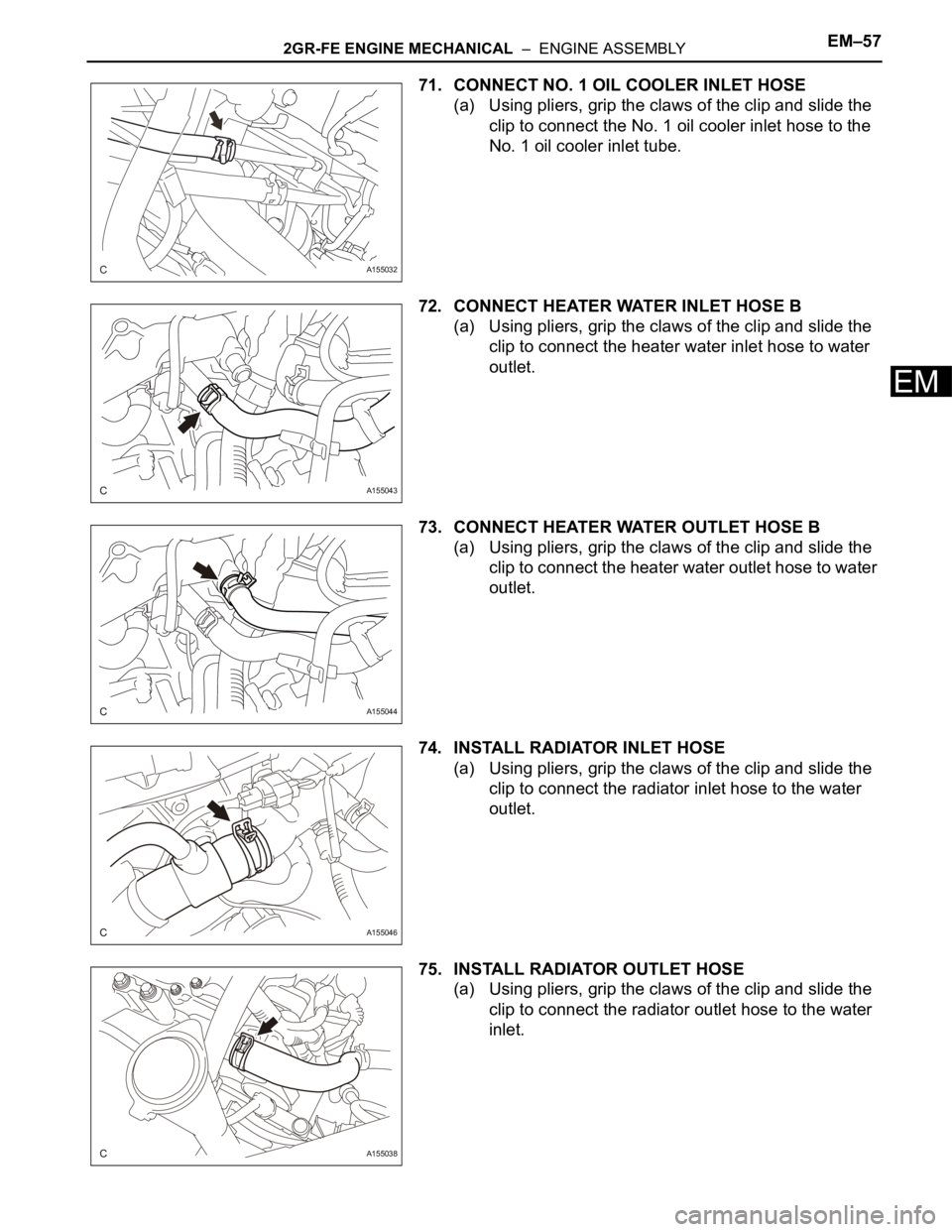
71. CONNECT NO. 1 OIL COOLER INLET HOSE
(a) Using pliers, grip the claws of the clip and slide the
clip to connect the No. 1 oil cooler inlet hose to the
No. 1 oil cooler inlet tube.
72. CONNECT HEATER WATER INLET HOSE B
(a) Using pliers, grip the claws of the clip and slide the
clip to connect the heater water inlet hose to water
outlet.
73. CONNECT HEATER WATER OUTLET HOSE B
(a) Using pliers, grip the claws of the clip and slide the
clip to connect the heater water outlet hose to water
outlet.
74. INSTALL RADIATOR INLET HOSE
(a) Using pliers, grip the claws of the clip and slide the
clip to connect the radiator inlet hose to the water
outlet.
75. INSTALL RADIATOR OUTLET HOSE
(a) Using pliers, grip the claws of the clip and slide the
clip to connect the radiator outlet hose to the water
inlet.
A155032
A155043
A155044
A155046
A155038
Page 1017 of 3000
EM–582GR-FE ENGINE MECHANICAL – ENGINE ASSEMBLY
EM
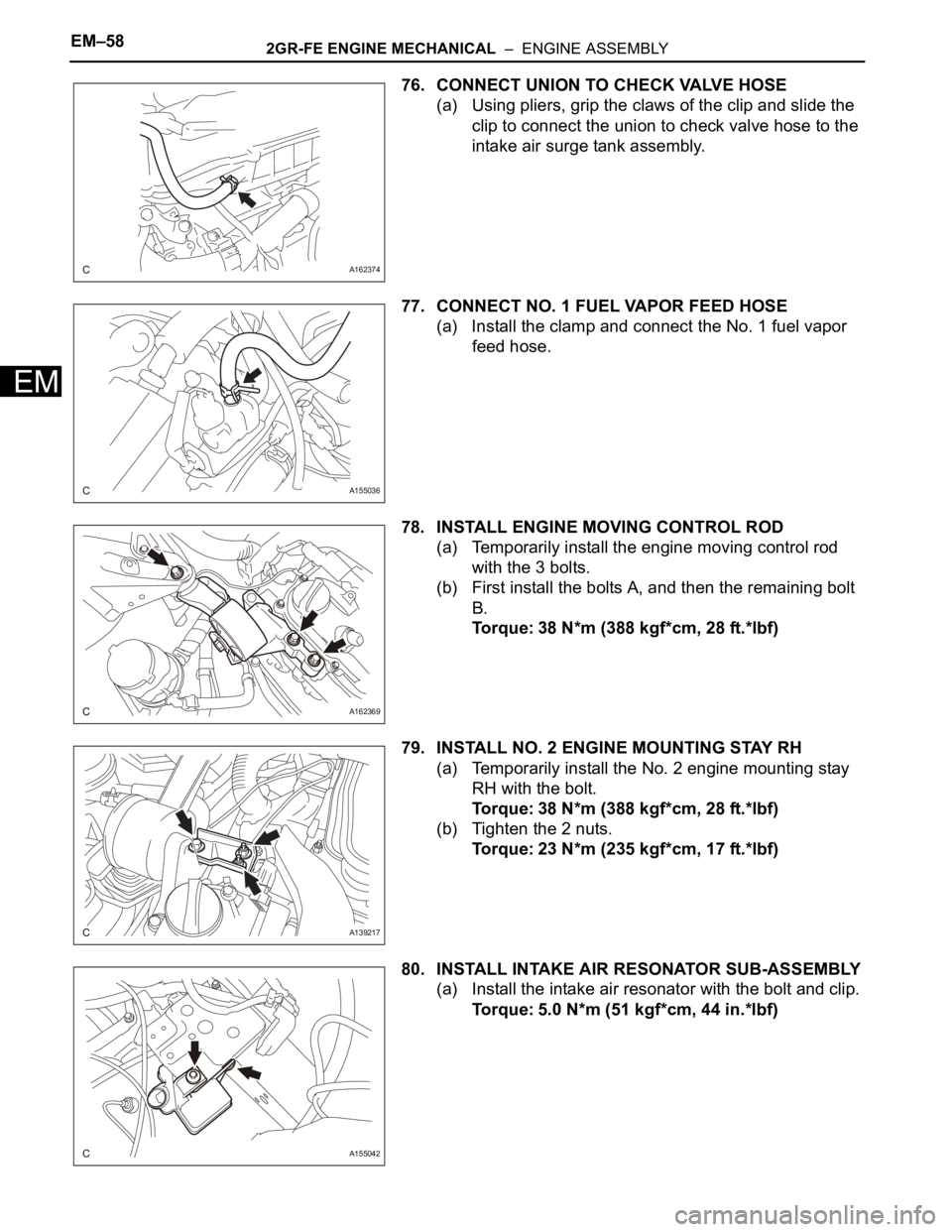
76. CONNECT UNION TO CHECK VALVE HOSE
(a) Using pliers, grip the claws of the clip and slide the
clip to connect the union to check valve hose to the
intake air surge tank assembly.
77. CONNECT NO. 1 FUEL VAPOR FEED HOSE
(a) Install the clamp and connect the No. 1 fuel vapor
feed hose.
78. INSTALL ENGINE MOVING CONTROL ROD
(a) Temporarily install the engine moving control rod
with the 3 bolts.
(b) First install the bolts A, and then the remaining bolt
B.
Torque: 38 N*m (388 kgf*cm, 28 ft.*lbf)
79. INSTALL NO. 2 ENGINE MOUNTING STAY RH
(a) Temporarily install the No. 2 engine mounting stay
RH with the bolt.
Torque: 38 N*m (388 kgf*cm, 28 ft.*lbf)
(b) Tighten the 2 nuts.
Torque: 23 N*m (235 kgf*cm, 17 ft.*lbf)
80. INSTALL INTAKE AIR RESONATOR SUB-ASSEMBLY
(a) Install the intake air resonator with the bolt and clip.
Torque: 5.0 N*m (51 kgf*cm, 44 in.*lbf)
A162374
A155036
A162369
A139217
A155042
Page 1018 of 3000
2GR-FE ENGINE MECHANICAL – ENGINE ASSEMBLYEM–59
EM
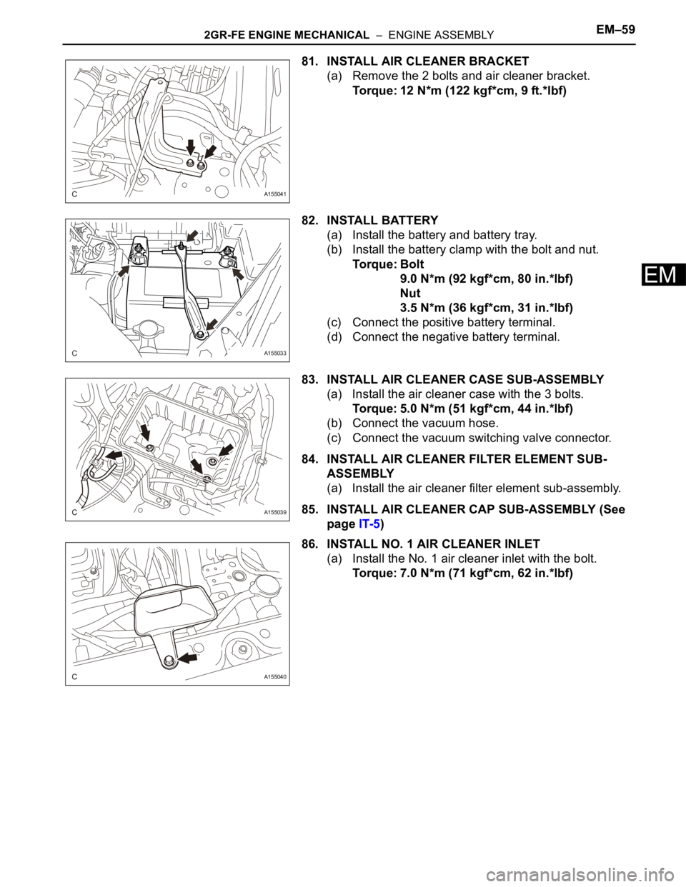
81. INSTALL AIR CLEANER BRACKET
(a) Remove the 2 bolts and air cleaner bracket.
Torque: 12 N*m (122 kgf*cm, 9 ft.*lbf)
82. INSTALL BATTERY
(a) Install the battery and battery tray.
(b) Install the battery clamp with the bolt and nut.
Torque: Bolt
9.0 N*m (92 kgf*cm, 80 in.*lbf)
Nut
3.5 N*m (36 kgf*cm, 31 in.*lbf)
(c) Connect the positive battery terminal.
(d) Connect the negative battery terminal.
83. INSTALL AIR CLEANER CASE SUB-ASSEMBLY
(a) Install the air cleaner case with the 3 bolts.
Torque: 5.0 N*m (51 kgf*cm, 44 in.*lbf)
(b) Connect the vacuum hose.
(c) Connect the vacuum switching valve connector.
84. INSTALL AIR CLEANER FILTER ELEMENT SUB-
ASSEMBLY
(a) Install the air cleaner filter element sub-assembly.
85. INSTALL AIR CLEANER CAP SUB-ASSEMBLY (See
page IT-5)
86. INSTALL NO. 1 AIR CLEANER INLET
(a) Install the No. 1 air cleaner inlet with the bolt.
Torque: 7.0 N*m (71 kgf*cm, 62 in.*lbf)
A155041
A155033
A155039
A155040
Page 1019 of 3000
EM–602GR-FE ENGINE MECHANICAL – ENGINE ASSEMBLY
EM
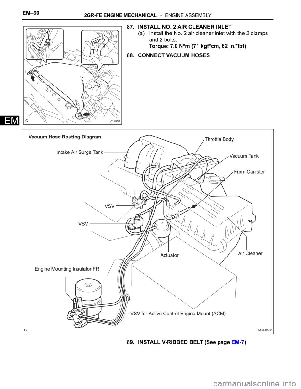
87. INSTALL NO. 2 AIR CLEANER INLET
(a) Install the No. 2 air cleaner inlet with the 2 clamps
and 2 bolts.
Torque: 7.0 N*m (71 kgf*cm, 62 in.*lbf)
88. CONNECT VACUUM HOSES
89. INSTALL V-RIBBED BELT (See page EM-7)
A133004
A133002E01
Page 1020 of 3000
2GR-FE ENGINE MECHANICAL – ENGINE ASSEMBLYEM–61
EM
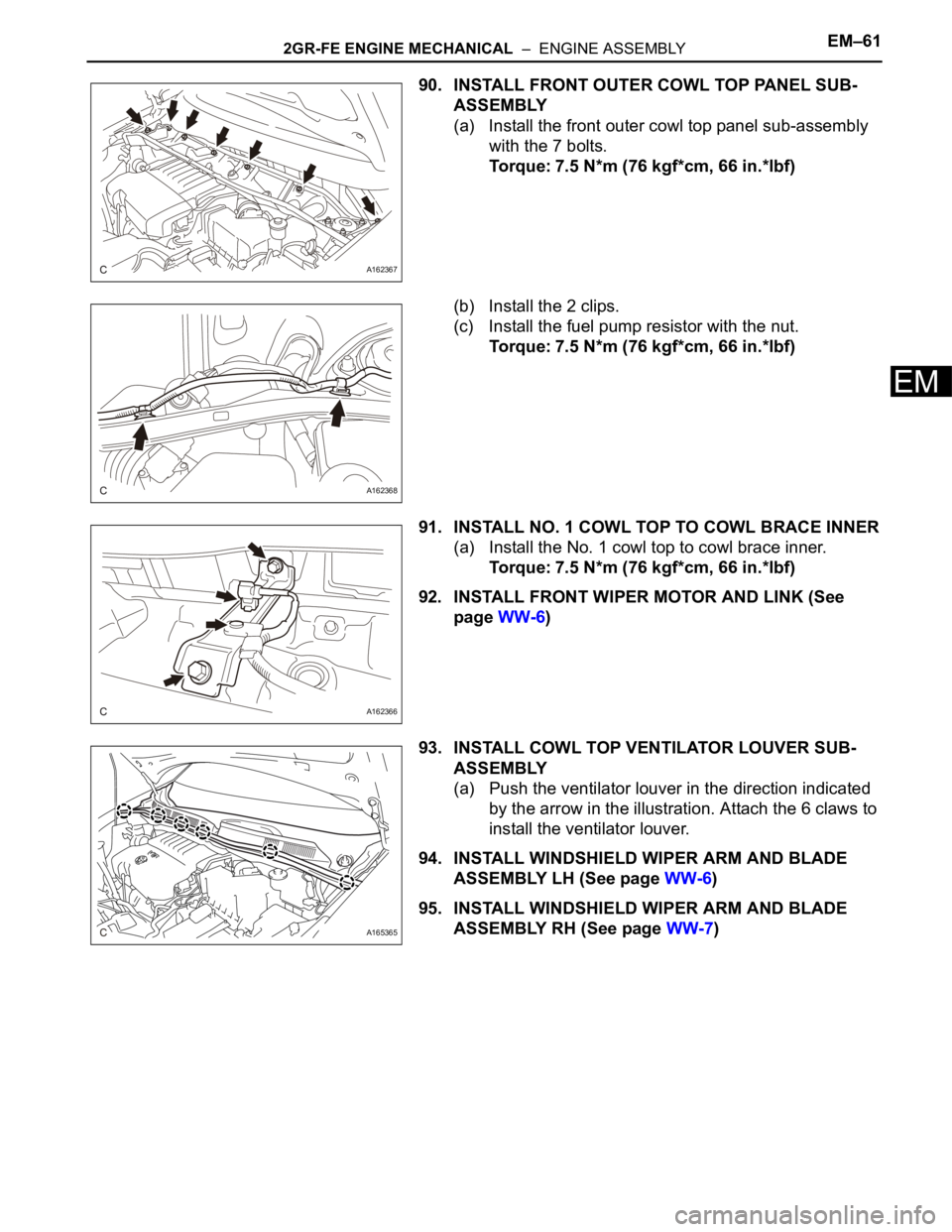
90. INSTALL FRONT OUTER COWL TOP PANEL SUB-
ASSEMBLY
(a) Install the front outer cowl top panel sub-assembly
with the 7 bolts.
Torque: 7.5 N*m (76 kgf*cm, 66 in.*lbf)
(b) Install the 2 clips.
(c) Install the fuel pump resistor with the nut.
Torque: 7.5 N*m (76 kgf*cm, 66 in.*lbf)
91. INSTALL NO. 1 COWL TOP TO COWL BRACE INNER
(a) Install the No. 1 cowl top to cowl brace inner.
Torque: 7.5 N*m (76 kgf*cm, 66 in.*lbf)
92. INSTALL FRONT WIPER MOTOR AND LINK (See
page WW-6)
93. INSTALL COWL TOP VENTILATOR LOUVER SUB-
ASSEMBLY
(a) Push the ventilator louver in the direction indicated
by the arrow in the illustration. Attach the 6 claws to
install the ventilator louver.
94. INSTALL WINDSHIELD WIPER ARM AND BLADE
ASSEMBLY LH (See page WW-6)
95. INSTALL WINDSHIELD WIPER ARM AND BLADE
ASSEMBLY RH (See page WW-7)
A162367
A162368
A162366
A165365