TOYOTA SIENNA 2007 Service Repair Manual
Manufacturer: TOYOTA, Model Year: 2007, Model line: SIENNA, Model: TOYOTA SIENNA 2007Pages: 3000, PDF Size: 52.26 MB
Page 941 of 3000
EM–1322GR-FE ENGINE MECHANICAL – ENGINE UNIT
EM
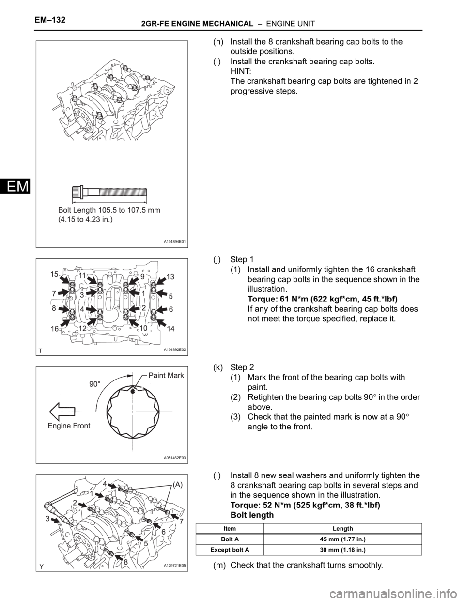
(h) Install the 8 crankshaft bearing cap bolts to the
outside positions.
(i) Install the crankshaft bearing cap bolts.
HINT:
The crankshaft bearing cap bolts are tightened in 2
progressive steps.
(j) Step 1
(1) Install and uniformly tighten the 16 crankshaft
bearing cap bolts in the sequence shown in the
illustration.
Torque: 61 N*m (622 kgf*cm, 45 ft.*lbf)
If any of the crankshaft bearing cap bolts does
not meet the torque specified, replace it.
(k) Step 2
(1) Mark the front of the bearing cap bolts with
paint.
(2) Retighten the bearing cap bolts 90
in the order
above.
(3) Check that the painted mark is now at a 90
angle to the front.
(l) Install 8 new seal washers and uniformly tighten the
8 crankshaft bearing cap bolts in several steps and
in the sequence shown in the illustration.
Torque: 52 N*m (525 kgf*cm, 38 ft.*lbf)
Bolt length
(m) Check that the crankshaft turns smoothly.
A134894E01
A134892E02
A051462E03
A129721E05
Item Length
Bolt A 45 mm (1.77 in.)
Except bolt A 30 mm (1.18 in.)
Page 942 of 3000
2GR-FE ENGINE MECHANICAL – ENGINE UNITEM–133
EM
(n) Check the crankshaft thrust clearance (See page
EM-118).
9. INSTALL CONNECTING ROD BEARING
(a) Install the connecting rod bearing to the connecting
rod and connecting rod cap.
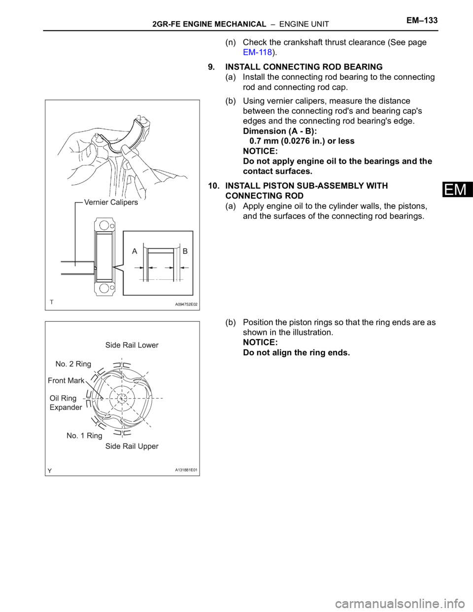
(b) Using vernier calipers, measure the distance
between the connecting rod's and bearing cap's
edges and the connecting rod bearing's edge.
Dimension (A - B):
0.7 mm (0.0276 in.) or less
NOTICE:
Do not apply engine oil to the bearings and the
contact surfaces.
10. INSTALL PISTON SUB-ASSEMBLY WITH
CONNECTING ROD
(a) Apply engine oil to the cylinder walls, the pistons,
and the surfaces of the connecting rod bearings.
(b) Position the piston rings so that the ring ends are as
shown in the illustration.
NOTICE:
Do not align the ring ends.
A094752E02
A131881E01
Page 943 of 3000
EM–1342GR-FE ENGINE MECHANICAL – ENGINE UNIT
EM
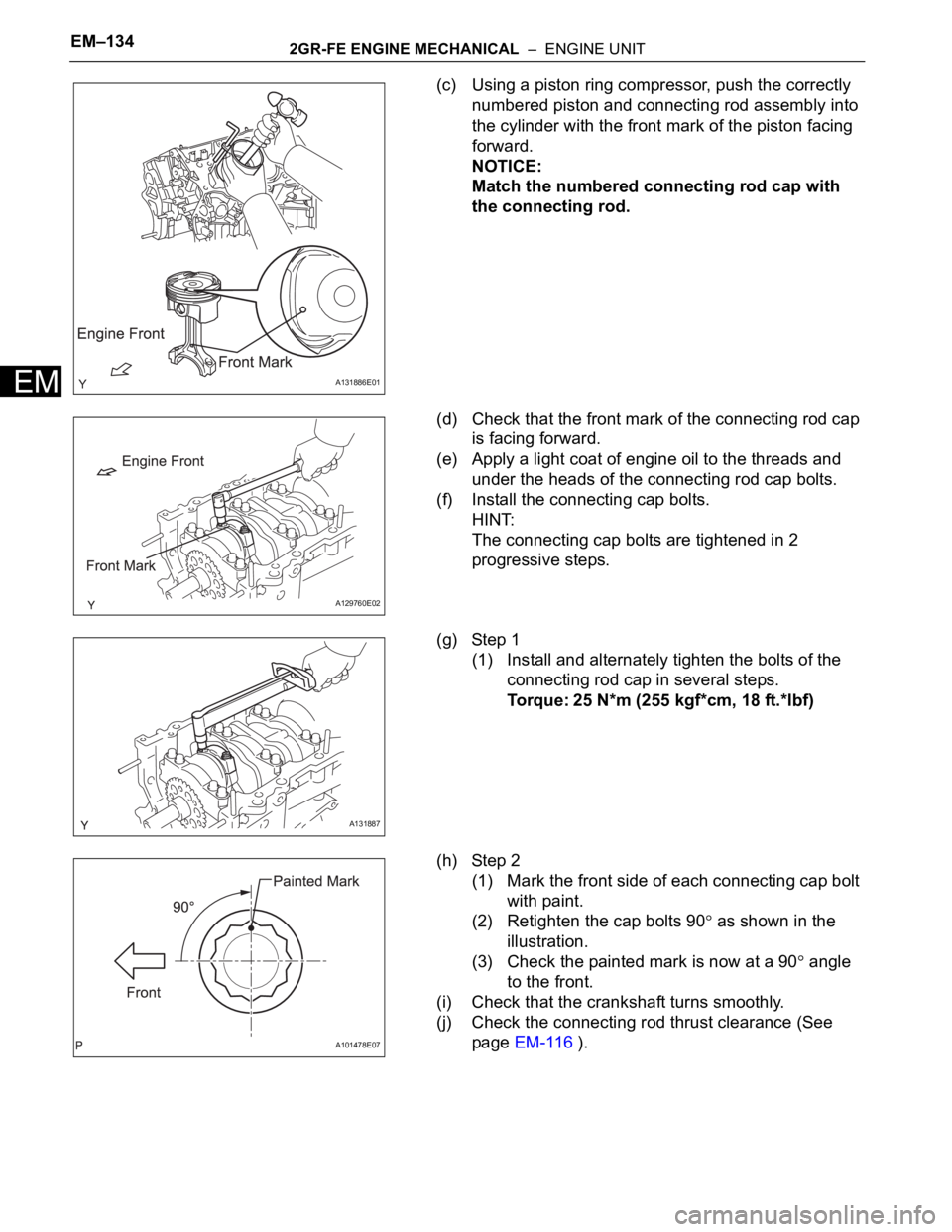
(c) Using a piston ring compressor, push the correctly
numbered piston and connecting rod assembly into
the cylinder with the front mark of the piston facing
forward.
NOTICE:
Match the numbered connecting rod cap with
the connecting rod.
(d) Check that the front mark of the connecting rod cap
is facing forward.
(e) Apply a light coat of engine oil to the threads and
under the heads of the connecting rod cap bolts.
(f) Install the connecting cap bolts.
HINT:
The connecting cap bolts are tightened in 2
progressive steps.
(g) Step 1
(1) Install and alternately tighten the bolts of the
connecting rod cap in several steps.
Torque: 25 N*m (255 kgf*cm, 18 ft.*lbf)
(h) Step 2
(1) Mark the front side of each connecting cap bolt
with paint.
(2) Retighten the cap bolts 90
as shown in the
illustration.
(3) Check the painted mark is now at a 90
angle
to the front.
(i) Check that the crankshaft turns smoothly.
(j) Check the connecting rod thrust clearance (See
page EM-116 ).
A131886E01
A129760E02
A131887
A101478E07
Page 944 of 3000
2GR-FE ENGINE MECHANICAL – ENGINE UNITEM–135
EM
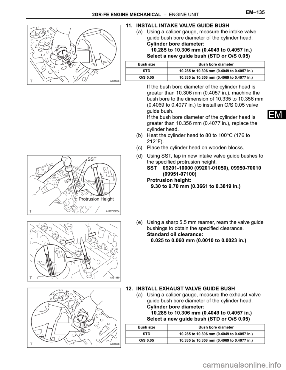
11. INSTALL INTAKE VALVE GUIDE BUSH
(a) Using a caliper gauge, measure the intake valve
guide bush bore diameter of the cylinder head.
Cylinder bore diameter:
10.285 to 10.306 mm (0.4049 to 0.4057 in.)
Select a new guide bush (STD or O/S 0.05)
If the bush bore diameter of the cylinder head is
greater than 10.306 mm (0.4057 in.), machine the
bush bore to the dimension of 10.335 to 10.356 mm
(0.4069 to 0.4077 in.) to install an O/S 0.05 valve
guide bush.
If the bush bore diameter of the cylinder head is
greater than 10.356 mm (0.4077 in.), replace the
cylinder head.
(b) Heat the cylinder head to 80 to 100
C (176 to
212
F).
(c) Place the cylinder head on wooden blocks.
(d) Using SST, tap in new intake valve guide bushes to
the specified protrusion height.
SST 09201-10000 (09201-01050), 09950-70010
(09951-07100)
Protrusion height:
9.30 to 9.70 mm (0.3661 to 0.3819 in.)
(e) Using a sharp 5.5 mm reamer, ream the valve guide
bushings to obtain the specified clearance.
Standard oil clearance:
0.025 to 0.060 mm (0.0010 to 0.0023 in.)
12. INSTALL EXHAUST VALVE GUIDE BUSH
(a) Using a caliper gauge, measure the exhaust valve
guide bush bore diameter of the cylinder head.
Cylinder bore diameter:
10.285 to 10.306 mm (0.4049 to 0.4057 in.)
Select a new guide bush (STD or O/S 0.05)
A109626
Bush size Bush bore diameter
STD 10.285 to 10.306 mm (0.4049 to 0.4057 in.)
O/S 0.05 10.335 to 10.356 mm (0.4069 to 0.4077 in.)
A120710E04
A131839
A109628
Bush size Bush bore diameter
STD 10.285 to 10.306 mm (0.4049 to 0.4057 in.)
O/S 0.05 10.335 to 10.356 mm (0.4069 to 0.4077 in.)
Page 945 of 3000
EM–1362GR-FE ENGINE MECHANICAL – ENGINE UNIT
EM
If the bush bore diameter of the cylinder head is
greater than 10.306 mm (0.4057 in.), machine the
bush bore to the dimension of 10.335 to 10.356 mm
(0.4069 to 0.4077 in.) to install an O/S 0.05 valve
guide bush.
If the bush bore diameter of the cylinder head is
greater than 10.356 mm (0.4077 in.), replace the
cylinder head.
(b) Heat the cylinder head to 80 to 100
C (176 to
212
F).
(c) Place the cylinder head on wooden blocks.
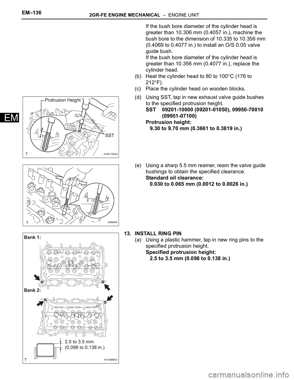
(d) Using SST, tap in new exhaust valve guide bushes
to the specified protrusion height.
SST 09201-10000 (09201-01050), 09950-70010
(09951-07100)
Protrusion height:
9.30 to 9.70 mm (0.3661 to 0.3819 in.)
(e) Using a sharp 5.5 mm reamer, ream the valve guide
bushings to obtain the specified clearance.
Standard oil clearance:
0.030 to 0.065 mm (0.0012 to 0.0026 in.)
13. INSTALL RING PIN
(a) Using a plastic hammer, tap in new ring pins to the
specified protrusion height.
Specified protrusion height:
2.5 to 3.5 mm (0.098 to 0.138 in.)
A120712E04
A096429
A131888E03
Page 946 of 3000
2GR-FE ENGINE MECHANICAL – ENGINE UNITEM–137
EM
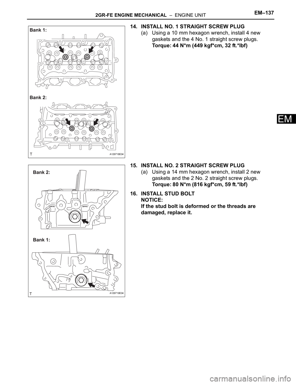
14. INSTALL NO. 1 STRAIGHT SCREW PLUG
(a) Using a 10 mm hexagon wrench, install 4 new
gaskets and the 4 No. 1 straight screw plugs.
Torque: 44 N*m (449 kgf*cm, 32 ft.*lbf)
15. INSTALL NO. 2 STRAIGHT SCREW PLUG
(a) Using a 14 mm hexagon wrench, install 2 new
gaskets and the 2 No. 2 straight screw plugs.
Torque: 80 N*m (816 kgf*cm, 59 ft.*lbf)
16. INSTALL STUD BOLT
NOTICE:
If the stud bolt is deformed or the threads are
damaged, replace it.
A129718E04
A129719E04
Page 947 of 3000
EM–1382GR-FE ENGINE MECHANICAL – ENGINE UNIT
EM
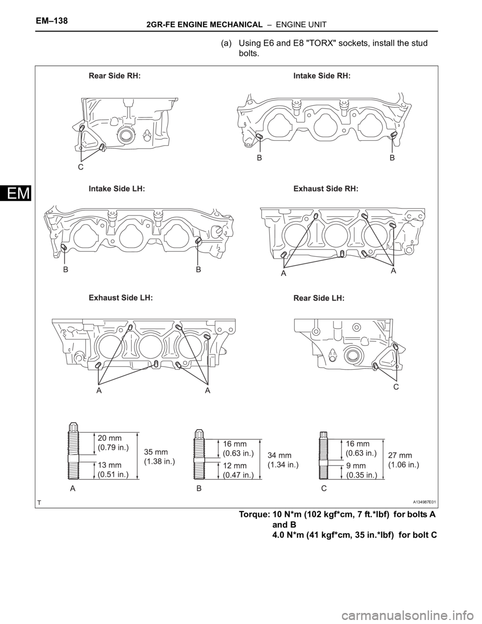
(a) Using E6 and E8 "TORX" sockets, install the stud
bolts.
Torque: 10 N*m (102 kgf*cm, 7 ft.*lbf) for bolts A
and B
4.0 N*m (41 kgf*cm, 35 in.*lbf) for bolt C
A134987E01
Page 948 of 3000
2GR-FE ENGINE MECHANICAL – ENGINE UNITEM–139
EM
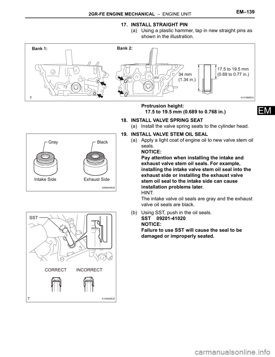
17. INSTALL STRAIGHT PIN
(a) Using a plastic hammer, tap in new straight pins as
shown in the illustration.
Protrusion height:
17.5 to 19.5 mm (0.689 to 0.768 in.)
18. INSTALL VALVE SPRING SEAT
(a) Install the valve spring seats to the cylinder head.
19. INSTALL VALVE STEM OIL SEAL
(a) Apply a light coat of engine oil to new valve stem oil
seals.
NOTICE:
Pay attention when installing the intake and
exhaust valve stem oil seals. For example,
installing the intake valve stem oil seal into the
exhaust side or installing the exhaust valve
stem oil seal to the intake side can cause
installation problems later.
HINT:
The intake valve oil seals are gray and the exhaust
valve oil seals are black.
(b) Using SST, push in the oil seals.
SST 09201-41020
NOTICE:
Failure to use SST will cause the seal to be
damaged or improperly seated.
A131890E03
A094934E04
A124592E02
Page 949 of 3000
EM–1402GR-FE ENGINE MECHANICAL – ENGINE UNIT
EM
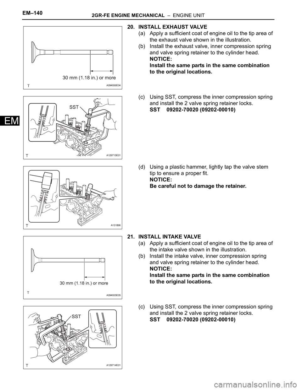
20. INSTALL EXHAUST VALVE
(a) Apply a sufficient coat of engine oil to the tip area of
the exhaust valve shown in the illustration.
(b) Install the exhaust valve, inner compression spring
and valve spring retainer to the cylinder head.
NOTICE:
Install the same parts in the same combination
to the original locations.
(c) Using SST, compress the inner compression spring
and install the 2 valve spring retainer locks.
SST 09202-70020 (09202-00010)
(d) Using a plastic hammer, lightly tap the valve stem
tip to ensure a proper fit.
NOTICE:
Be careful not to damage the retainer.
21. INSTALL INTAKE VALVE
(a) Apply a sufficient coat of engine oil to the tip area of
the intake valve shown in the illustration.
(b) Install the intake valve, inner compression spring
and valve spring retainer to the cylinder head.
NOTICE:
Install the same parts in the same combination
to the original locations.
(c) Using SST, compress the inner compression spring
and install the 2 valve spring retainer locks.
SST 09202-70020 (09202-00010)
A094936E04
A129715E01
A131896
A094935E05
A129714E01
Page 950 of 3000
2GR-FE ENGINE MECHANICAL – ENGINE UNITEM–141
EM
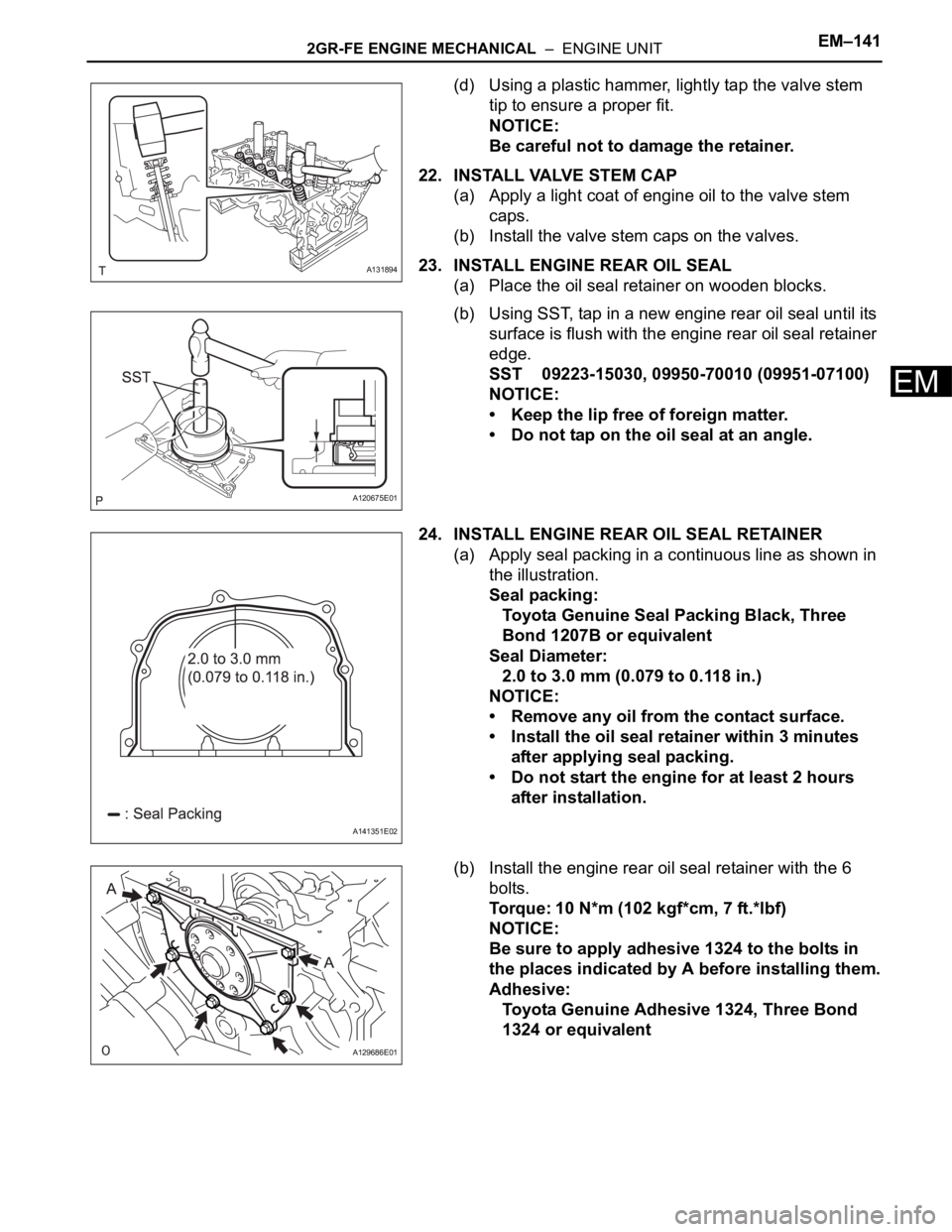
(d) Using a plastic hammer, lightly tap the valve stem
tip to ensure a proper fit.
NOTICE:
Be careful not to damage the retainer.
22. INSTALL VALVE STEM CAP
(a) Apply a light coat of engine oil to the valve stem
caps.
(b) Install the valve stem caps on the valves.
23. INSTALL ENGINE REAR OIL SEAL
(a) Place the oil seal retainer on wooden blocks.
(b) Using SST, tap in a new engine rear oil seal until its
surface is flush with the engine rear oil seal retainer
edge.
SST 09223-15030, 09950-70010 (09951-07100)
NOTICE:
• Keep the lip free of foreign matter.
• Do not tap on the oil seal at an angle.
24. INSTALL ENGINE REAR OIL SEAL RETAINER
(a) Apply seal packing in a continuous line as shown in
the illustration.
Seal packing:
Toyota Genuine Seal Packing Black, Three
Bond 1207B or equivalent
Seal Diameter:
2.0 to 3.0 mm (0.079 to 0.118 in.)
NOTICE:
• Remove any oil from the contact surface.
• Install the oil seal retainer within 3 minutes
after applying seal packing.
• Do not start the engine for at least 2 hours
after installation.
(b) Install the engine rear oil seal retainer with the 6
bolts.
Torque: 10 N*m (102 kgf*cm, 7 ft.*lbf)
NOTICE:
Be sure to apply adhesive 1324 to the bolts in
the places indicated by A before installing them.
Adhesive:
Toyota Genuine Adhesive 1324, Three Bond
1324 or equivalent
A131894
A120675E01
A141351E02
A129686E01