TOYOTA TACOMA 2019 Owners Manual (in English)
Manufacturer: TOYOTA, Model Year: 2019, Model line: TACOMA, Model: TOYOTA TACOMA 2019Pages: 700, PDF Size: 12.83 MB
Page 291 of 700
2914-5. Using the driving support systems
4
Driving
BSM (Blind Spot Monitor)
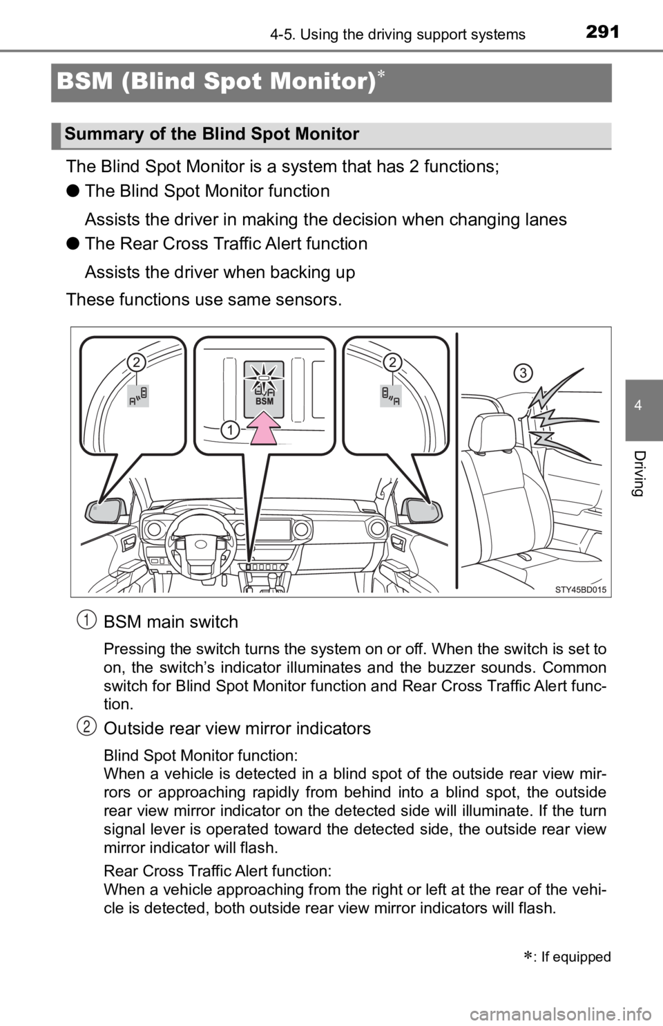
The Blind Spot Monitor is a system that has 2 functions;
● The Blind Spot Monitor function
Assists the driver in making t he decision when changing lanes
● The Rear Cross Traffic Alert function
Assists the driver when backing up
These functions use same sensors.
BSM main switch
Pressing the switch turns the system on or off. When the switch is set to
on, the switch’s indicator illuminates and the buzzer sounds. C ommon
switch for Blind Spot Monitor function and Rear Cross Traffic A lert func-
tion.
Outside rear view mirror indicators
Blind Spot Monitor function:
When a vehicle is detected in a blind spot of the outside rear view mir-
rors or approaching rapidly from behind into a blind spot, the outside
rear view mirror indicator on the detected side will illuminate. If the turn
signal lever is operated toward the detected side, the outside rear view
mirror indicator will flash.
Rear Cross Traffic Alert function:
When a vehicle approaching from the right or left at the rear of the vehi-
cle is detected, both outside rear view mirror indicators will flash.
: If equipped
Summary of the Blind Spot Monitor
1
2
Page 292 of 700
2924-5. Using the driving support systems
Rear Cross Traffic Alert buzzer (Rear Cross Traffic Alert funct ion
only)
When a vehicle approaching from the right or left rear of the v ehicle is
detected, a buzzer sounds from behind the left-hand rear pillar .
■The outside rear view mirror indicators visibility
When under strong sunlight, the outside rear view mirror indica tor may be dif-
ficult to see.
■ Rear Cross Traffic Alert buzzer hearing
Rear Cross Traffic Alert function may be difficult to hear over noises such as
high audio volume.
■ When there is a malfunction in the Blind Spot Monitor system
If a system malfunction is detected due to any of the following reasons, warn-
ing messages will be displayed: ( P. 582)
● There is a malfunction with the sensors
● The sensors have become dirty
● The outside temperature is extremely high or low
● The sensor voltage has become abnormal
■ Certification for the Blind Spot Monitor system
For vehicles sold in the U.S.A.
FCC ID: OAYSRR2A
This device complies with part 15 of the FCC Rules. Operation is subject to
the following two conditions:
(1) This device may not cause harmful interference, and
(2) this device must accept any interference received, includin g interference
that may cause undesired operation.
FCC Warning
Changes or modifications not expressly approved by the party re sponsible for
compliance could void the user’s authority to operate the equip ment.
For vehicles sold in Canada
Applicable law: Canada 310
This device complies with Industry Canada licence-exempt RSS standard(s).
Operation is subject to the following two conditions: (1) this device may not
cause interference, and (2) this device must accept any interfe rence, includ-
ing interference that may cause undesired operation of the devi ce.
Frequency bands: 24.05 – 24.25 GHz
Output power: less than 20 milliwatts
3
Page 293 of 700
2934-5. Using the driving support systems
4
Driving
Droit applicable : Canada 310
Le présent appareil est conforme aux CNR d’Industrie Canada applicables
aux appareils radio exempts de licence. L’exploitation est autorisée aux deux
conditions suivantes : (1) I’appareil ne doit pas produire de b rouillage, et (2)
I’utilisateur de I’appareil doit accepter tout brouillage radioélectrique subi,
même si le brouillage est susceptible d’en compromettre le foun ctionnement.
Bandes de fréquences : 24.05 – 24.25 GHz
Puissance émise : Moins de 20 milliwatts
The Blind Spot Monitor function uses radar sensors to detect ve hicles
that are traveling in an adjacent lane in the area that is not reflected in
the outside rear view mirror (the blind spot), and advises the driver of
the vehicles existence via the outside rear view mirror indicat o r.
WARNING
■Handling the radar sensor
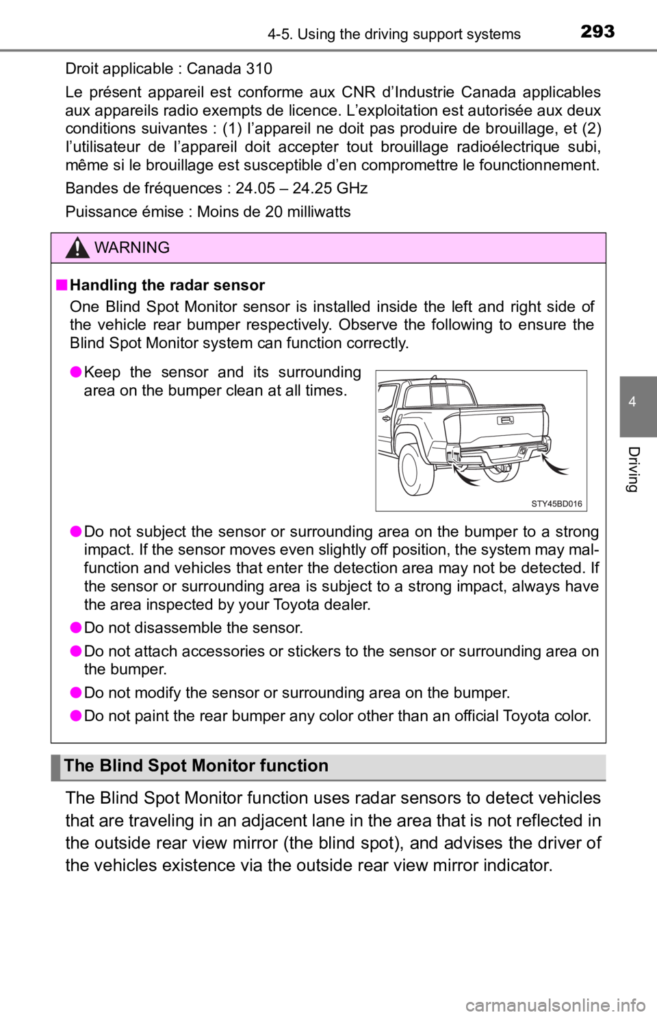
One Blind Spot Monitor sensor is installed inside the left and right side of
the vehicle rear bumper respectively. Observe the following to ensure the
Blind Spot Monitor system can function correctly.
● Do not subject the sensor or surrounding area on the bumper to a strong
impact. If the sensor moves even slightly off position, the system may mal-
function and vehicles that enter the detection area may not be detected. If
the sensor or surrounding area is subject to a strong impact, always have
the area inspected by your Toyota dealer.
● Do not disassemble the sensor.
● Do not attach accessories or stickers to the sensor or surrounding area on
the bumper.
● Do not modify the sensor or surrounding area on the bumper.
● Do not paint the rear bumper any color other than an official Toyota color.
The Blind Spot Monitor function
●Keep the sensor and its surrounding
area on the bumper clean at all times.
Page 294 of 700
2944-5. Using the driving support systems
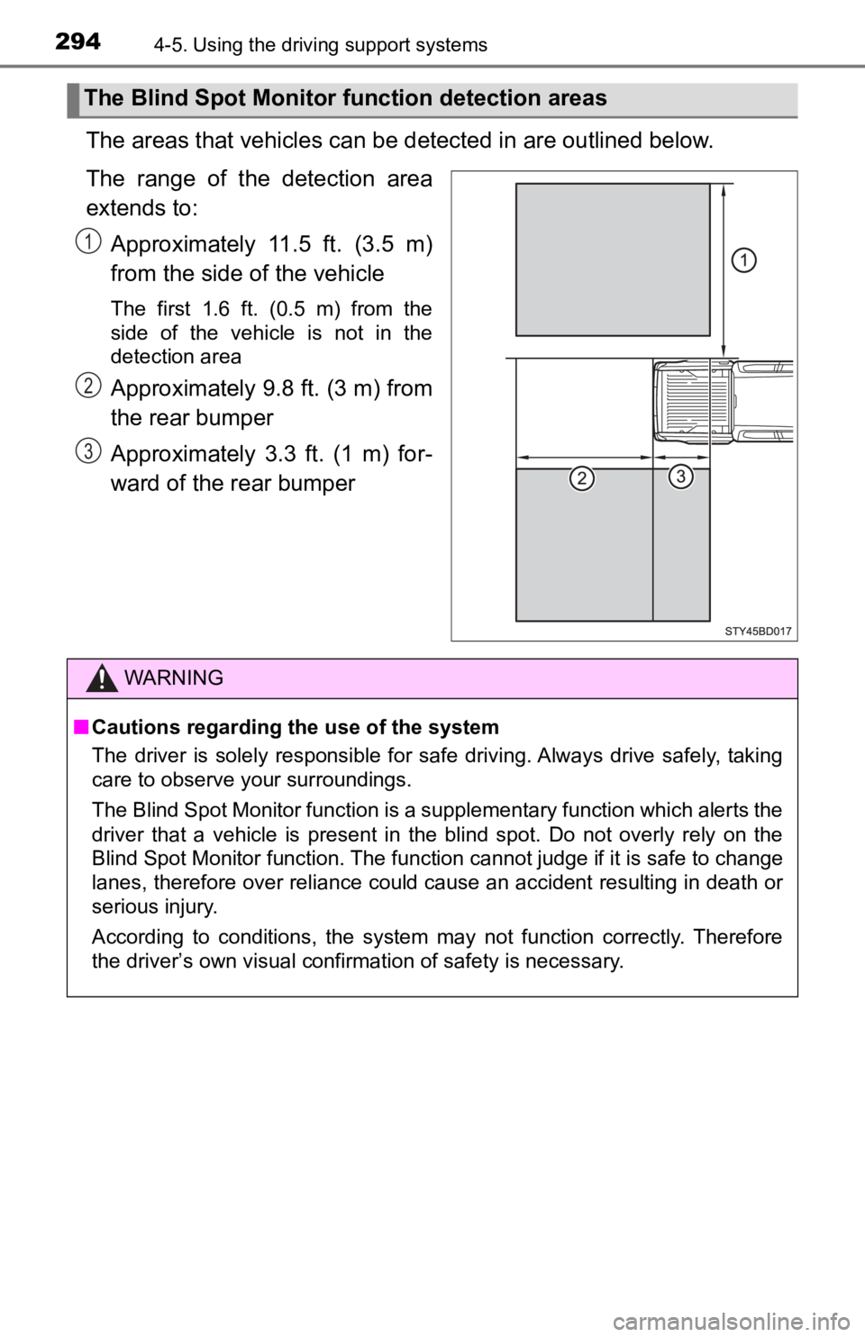
The areas that vehicles can be detected in are outlined below.
The range of the detection area
extends to:
Approximately 11.5 ft. (3.5 m)
from the side of the vehicle
The first 1.6 ft. (0.5 m) from the
side of the vehicle is not in the
detection area
Approximately 9.8 ft. (3 m) from
the rear bumper
Approximately 3.3 ft. (1 m) for-
ward of the rear bumper
The Blind Spot Monitor f unction detection areas
1
2
3
WARNING
■Cautions regarding the use of the system
The driver is solely responsible for safe driving. Always drive safely, taking
care to observe your surroundings.
The Blind Spot Monitor function is a supplementary function which alerts the
driver that a vehicle is present in the blind spot. Do not over ly rely on the
Blind Spot Monitor function. The function cannot judge if it is safe to change
lanes, therefore over reliance could cause an accident resultin g in death or
serious injury.
According to conditions, the system may not function correctly. Therefore
the driver’s own visual confirmation of safety is necessary.
Page 295 of 700
2954-5. Using the driving support systems
4
Driving
■The Blind Spot Monitor function is operational when
●The BSM main switch is set to on.
● Vehicle speed is greater than approximately 10 mph (16 km/h)
■ The Blind Spot Monitor functio n will detect a vehicle when
● A vehicle in an adjacent lane overtakes the vehicle.
● Another vehicle enters the detection area when it changes lanes .
■ Conditions under which the Blind Spot Monitor function will not detect a
vehicle
The Blind Spot Monitor function is not designed to detect the f ollowing types
of vehicles and/or objects:
● Small motorcycles, bicycles, pedestrians, etc.
*
●Vehicles traveling in the opposite direction
● Guardrails, walls, signs, parked vehicles and similar stationar y objects
*
●Following vehicles that are in the same lane*
●Vehicles driving 2 lanes across from your vehicle*
*
: Depending on conditions, detection of a vehicle and/or object may occur
■ Conditions under which the Blind Spot Monitor function may not func-
tion correctly
● The Blind Spot Monitor function may not detect vehicles correct ly in the fol-
lowing conditions:
• During bad weather such as heavy rain, fog, snow, etc.
• When ice or mud, etc., is attached to the rear bumper
• When driving on a road surface that is wet due to rain, standi ng water,
etc.
• When there is a significant difference in speed between your v ehicle and
the vehicle that enters the detection area
• When a vehicle is in the detection area from a stop and remains in the detection area as your vehicle accelerates
• When driving up or down consecutive steep inclines, such as hills, a dip
in the road, etc.
• When multiple vehicles approach with only a small gap between each vehicle
• When vehicle lanes are wide, and the vehicle in the next lane is too far
away from your vehicle
• When the vehicle that enters the detection area is traveling a t about the
same speed as your vehicle
• When towing anything such as trailer, boat, etc.
• When there is a significant difference in height between your vehicle and
the vehicle that enters the detection area
• Directly after the BSM main switch is set to on
• When items such as a bicycle carrier are installed on the rear of the vehi-
cle
Page 296 of 700
2964-5. Using the driving support systems
●Instances of the Blind Spot Monitor function unnecessarily dete cting a vehi-
cle and/or object may increase under the following conditions:
• When there is only a short distance between your vehicle and a guardrail,
wall, etc.
• When there is only a short distance between your vehicle and a following
vehicle
• When vehicle lanes are narrow and a vehicle driving 2 lanes ac ross from
your vehicle enters the detection area
• When items such as a bicycle carrier are installed on the rear of the vehi-
cle
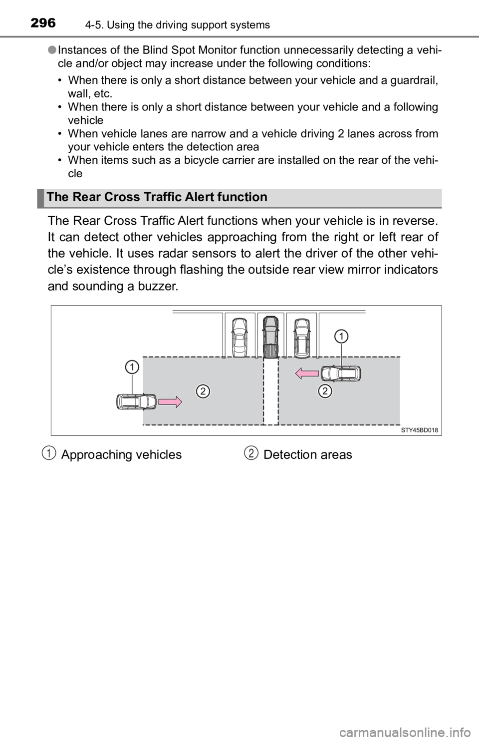
The Rear Cross Traffic Alert func tions when your vehicle is in reverse.
It can detect other vehicles appr oaching from the right or left rear of
the vehicle. It uses radar sensors to alert the driver of the other vehi-
cle’s existence through flashing the outside rear view mirror i ndicators
and sounding a buzzer.
The Rear Cross Tra ffic Alert function
Approaching vehicles Detection areas12
Page 297 of 700
2974-5. Using the driving support systems
4
Driving
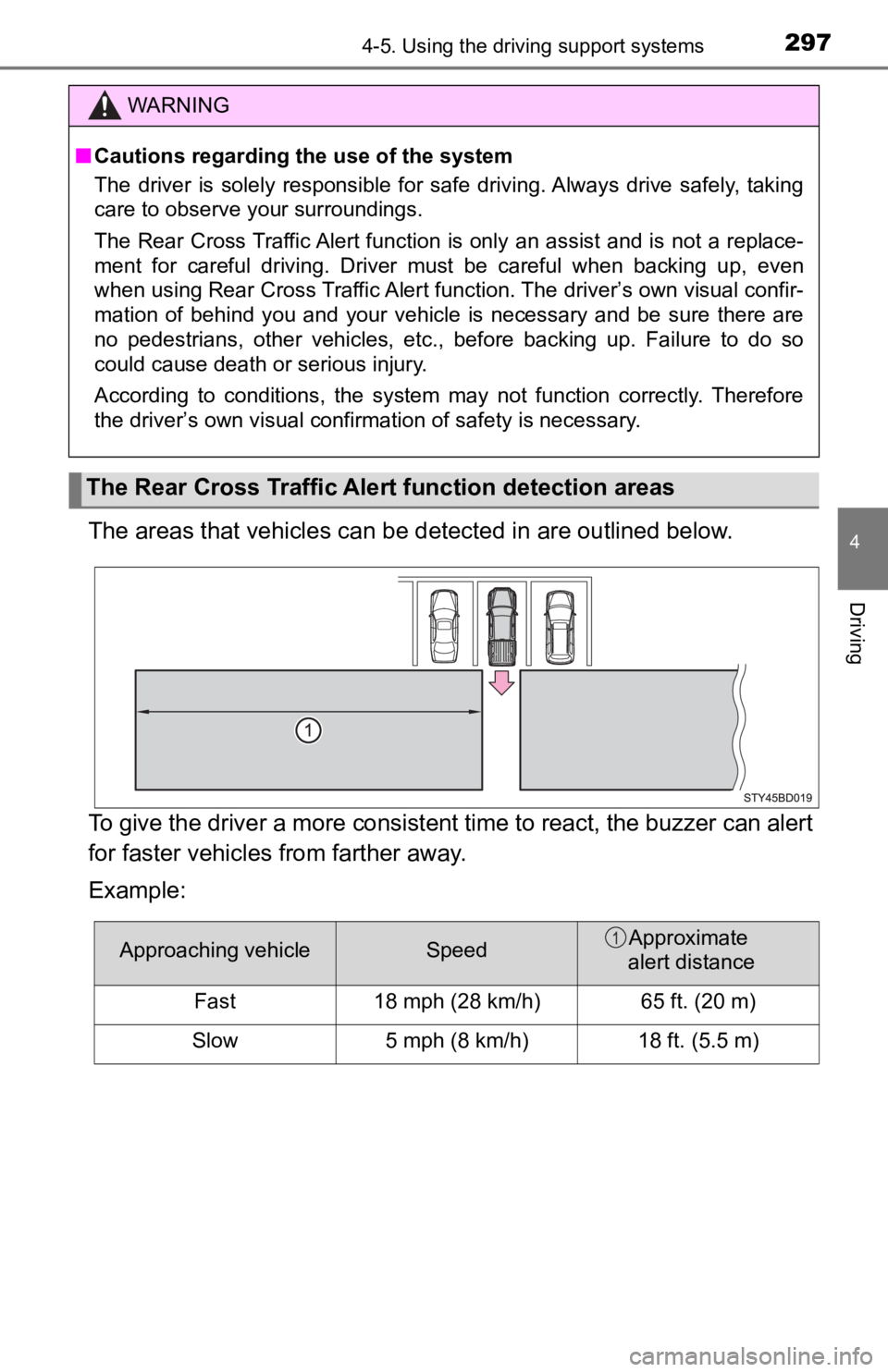
The areas that vehicles can be detected in are outlined below.
To give the driver a more consistent time to react, the buzzer can alert
for faster vehicles from farther away.
Example:
WARNING
■ Cautions regarding the use of the system
The driver is solely responsible for safe driving. Always drive safely, taking
care to observe your surroundings.
The Rear Cross Traffic Alert function is only an assist and is not a replace-
ment for careful driving. Driver must be careful when backing u p, even
when using Rear Cross Traffic Al ert function. The driver’s own visual confir-
mation of behind you and your vehicle is necessary and be sure there are
no pedestrians, other vehicles, etc., before backing up. Failure to do so
could cause death or serious injury.
According to conditions, the system may not function correctly. Therefore
the driver’s own visual confirmation of safety is necessary.
The Rear Cross Traffic Alert function detection areas
Approaching vehicleSpeedApproximate
alert distance
Fast 18 mph (28 km/h) 65 ft. (20 m)
Slow 5 mph (8 km/h) 18 ft. (5.5 m)1
Page 298 of 700
2984-5. Using the driving support systems
■The Rear Cross Traffic Alert function is operational when
● The BSM main switch is set to on.
● The shift lever is in R.
● Vehicle speed is less than approximately 5 mph (8 km/h).
● Approaching vehicle speed is between approximately 5 mph (8 km/ h) and
18 mph (28 km/h).
■ Conditions under which the Rear C ross Traffic Alert function will not
detect a vehicle
The Rear Cross Traffic Alert function is not designed to detect the following
types of vehicles and/or objects.
● Small motorcycles, bicycles, pedestrians, etc.
*
●Vehicles approaching from directly behind
● Guardrails, walls, signs, parked vehicles and similar stationar y objects
*
●Vehicles moving away from your vehicle
● Vehicles approaching from the parking spaces next to your vehic le
*
●Vehicles backing up in the parking space next to your vehicle*
*
: Depending on conditions, detection of a vehicle and/or object may occur.
■ Conditions under which the Rear C ross Traffic Alert function may not
function correctly
The Rear Cross Traffic Alert function may not detect vehicles c orrectly in the
following conditions.
● When ice or mud, etc., is attached to the rear bumper
● During bad weather such as heavy rain, fog, snow, etc.
● When multiple vehicles approach continuously
● Shallow angle parking
● When a vehicle is approaching at high speed
● When parking on a steep incline, such as hills, a dip in the ro ad, etc.
● Directly after the BSM main switch is set to on
● Directly after the engine is started with the BSM main switch o n
● When towing a trailer
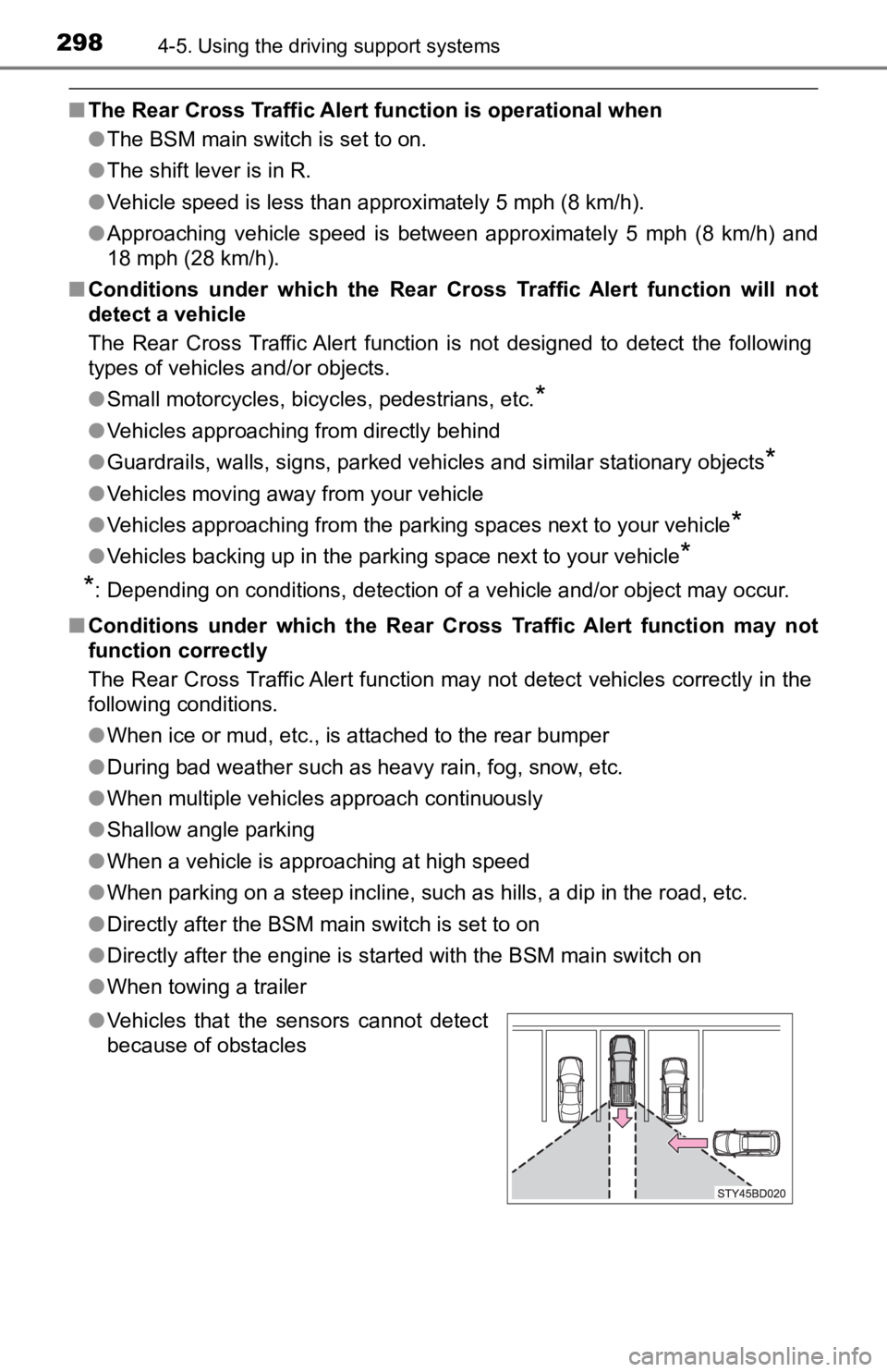
● Vehicles that the sensors cannot detect
because of obstacles
Page 299 of 700
2994-5. Using the driving support systems
4
Driving
Four-wheel drive system
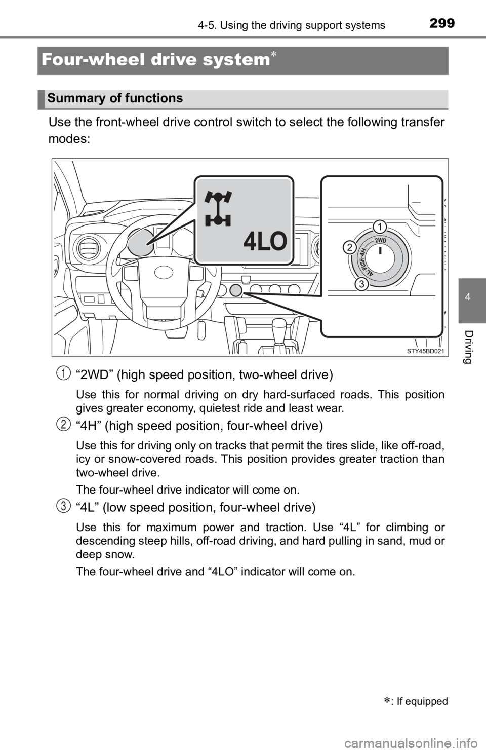
Use the front-wheel drive control switch to select the following transfer
modes:“2WD” (high speed position, two-wheel drive)
Use this for normal driving on dry hard-surfaced roads. This po sition
gives greater economy, quietest ride and least wear.
“4H” (high speed position, four-wheel drive)
Use this for driving only on tracks that permit the tires slide, like off-road,
icy or snow-covered roads. This position provides greater traction than
two-wheel drive.
The four-wheel drive indicator will come on.
“4L” (low speed position, four-wheel drive)
Use this for maximum power and traction. Use “4L” for climbing or
descending steep hills, off-road driving, and hard pulling in s and, mud or
deep snow.
The four-wheel drive and “4LO” indicator will come on.
: If equipped
Summary of functions
1
2
3
Page 300 of 700
3004-5. Using the driving support systems
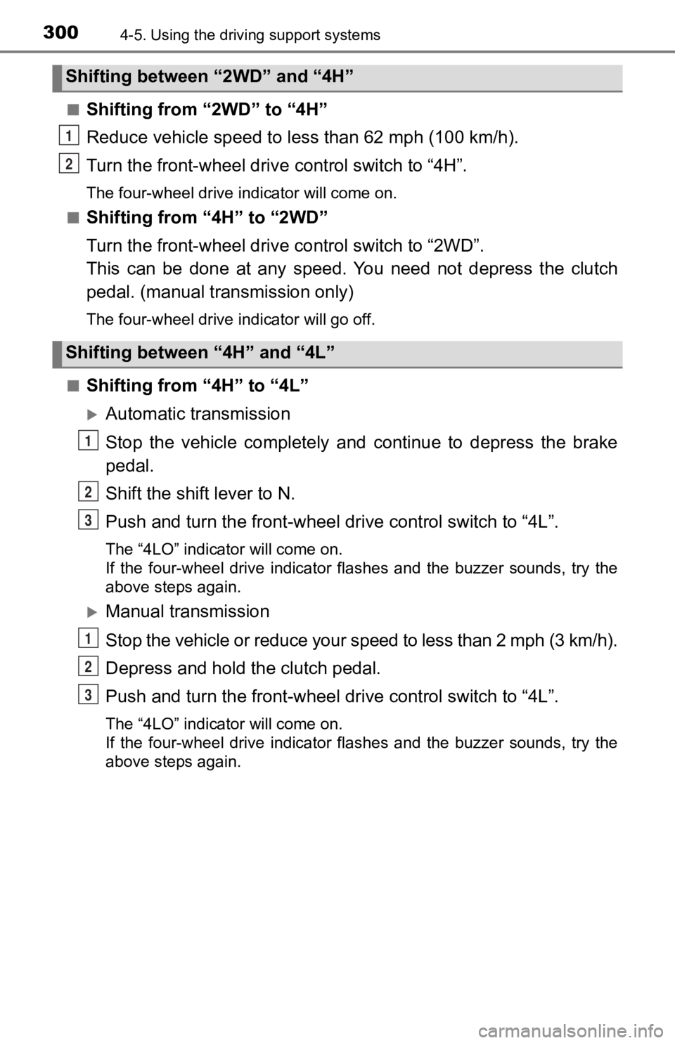
■Shifting from “2WD” to “4H”
Reduce vehicle speed to less than 62 mph (100 km/h).
Turn the front-wheel drive control switch to “4H”.
The four-wheel drive indicator will come on.
■
Shifting from “4H” to “2WD”
Turn the front-wheel drive co ntrol switch to “2WD”.
This can be done at any speed. Y ou need not depress the clutch
pedal. (manual transmission only)
The four-wheel drive indicator will go off.
■
Shifting from “4H” to “4L”
Automatic transmission
Stop the vehicle completely and continue to depress the brake
pedal.
Shift the shift lever to N.
Push and turn the front-wheel drive control switch to “4L”.
The “4LO” indicator will come on.
If the four-wheel drive indicator flashes and the buzzer sounds, try the
above steps again.
Manual transmission
Stop the vehicle or reduce your speed to less than 2 mph (3 km/ h).
Depress and hold the clutch pedal.
Push and turn the front-wheel drive control switch to “4L”.
The “4LO” indicator will come on.
If the four-wheel drive indicator flashes and the buzzer sounds, try the
above steps again.
Shifting between “2WD” and “4H”
Shifting between “4H” and “4L”
1
2
1
2
3
1
2
3