TOYOTA TERCEL 1985 Repair Manual
TERCEL 1985
TOYOTA
TOYOTA
https://www.carmanualsonline.info/img/14/57472/w960_57472-0.png
TOYOTA TERCEL 1985 Repair Manual
Trending: brake light, steering wheel, tire pressure, four wheel drive, oil viscosity, weight, ECU
Page 471 of 885
Page 472 of 885
Page 473 of 885
Page 474 of 885
Page 475 of 885
PR-1
PROPELLER SHAFT
(for 4WDl
PRECAUTIONS
TROUBLESHOOTING
PROPELLER SHAFT
Page
PR.2
PR-2
PR.2
ril:t'
ry*';'"'"s, 'f,'
$gu
Page 476 of 885
PR-z PROPELLER SHAFT - Precautions, Troubleshooting, Propeller Shaft
PRECAUTIONS
1. As the universal ioint is a non-disassembly type' the
propeller shaft or intermediate shaft must be replaced
as an assembly in the event of universalioint trouble.
2. Be careful not to grip the propeller shaft tube too tight-
ly in the vise as this will cause deformation.
TROUBLESHOOTING
ProblemPossible causeRemedyPage
NoiseSleeve yoke spline worn
Center bearing worn
Spider bearing worn or stuck
Replace intermediate shaft
Replace center bearing
Replace intermediate shaft or
propeller shaft
PR-3
PR-3
PR-3
VibrationPropeller shaft runout
Propeller shaft unbalance
Transmission extension housing rear
bushing worn
Sleeve yoke spline stuck
Center bearing height imProPer
Replace propeller shaft
Balance propeller shaft
Replace bushing
Replace intermediate shaft
Adjust bearing height
PR-3
PR-3
TA.4O
PR-3
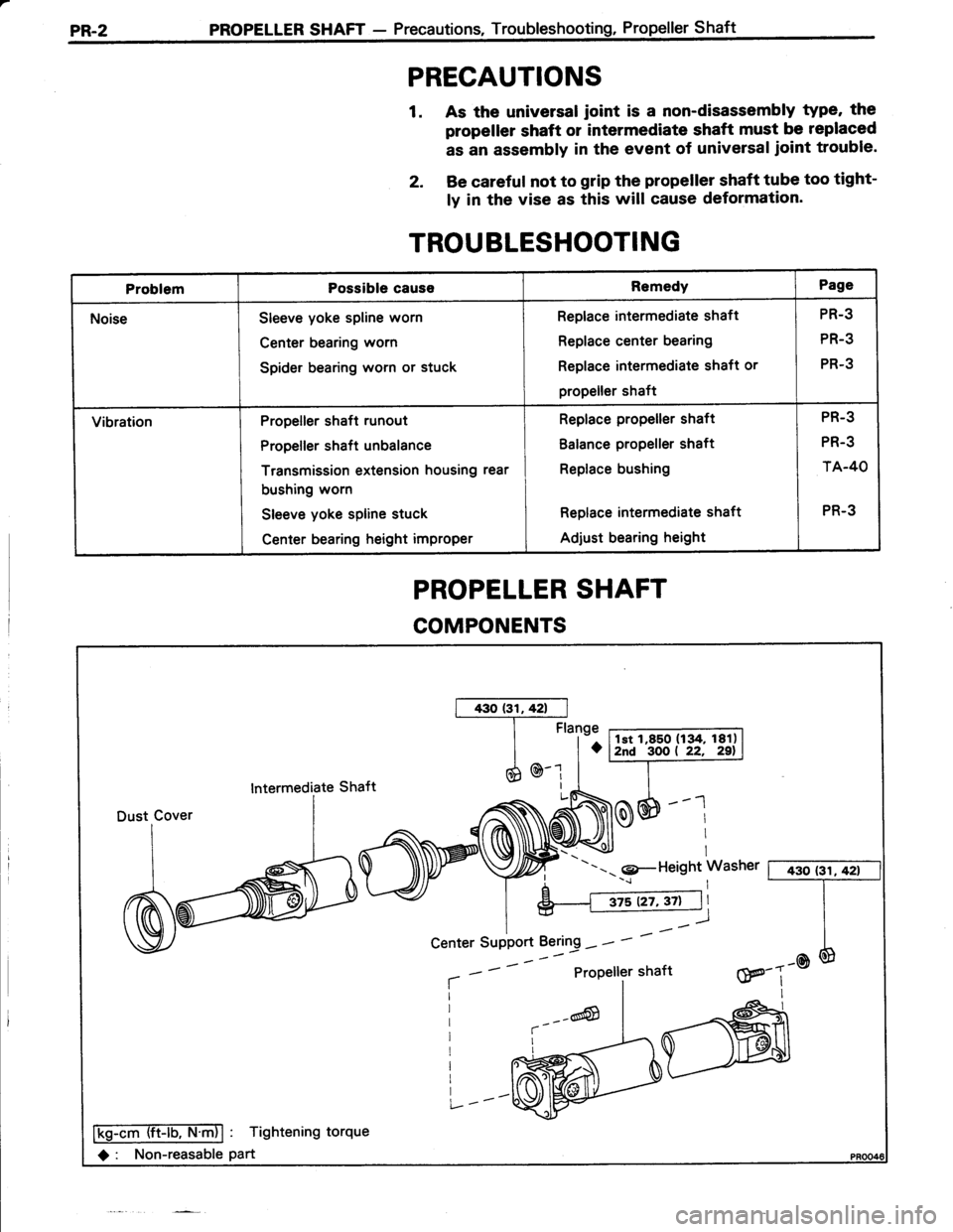
PROPELLER SHAFT
COMPONENTS
lntermediate Shaft
---- 9-Height Washer [ 430 (3il42t
aProPeller shaftw---@III
Ffiffiiib-ntnl : Tightening torque
O : Non-reasable part
Center SuPPort Bering - -
Page 477 of 885
PROPELLER SHAFT - Propeller ShaftPR.3
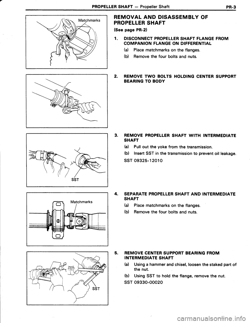
REMOVAL AND DISASSEMBLY OF
PROPELLER SHAFT
(See page PR-21
1. DISCONNECT PROPELLER SHAFT FLANGE FROM
COMPANION FLANGE ON DIFFERENTIAL
(a) Place matchmarks on the flanges.
(b) Remove the four bolts and nuts.
2. REMOVE TWO BOLTS HOLDING CENTER SUPPORT
BEARING TO BODY
3. REMOVE PROPELLER SHAFT WITH INTERMEDIATE
SHAFT
h) Pull out the yoke from the transmission.
(b) Insert SST in the transmission to prevent oil leakage.
ssT 09325-1 20rO
4. SEPARATE PROPELLER SHAFT AND INTERMEDIATE
SHAFT
(a) Place matchmarks on the flanges.
(b) Remove the four bolts and nuts.
5. REMOVE CENTER SUPPORT BEARING FROM
INTERMEDIATE SHAFT
(a) Using a hammer and chisel, loosen the staked part of
the nut.
(b) Using SST to hold the flange, remove the nut.
ssT 09330-00020
Page 478 of 885
PR-4PROPELLER SHAFT - Propeller Shaft
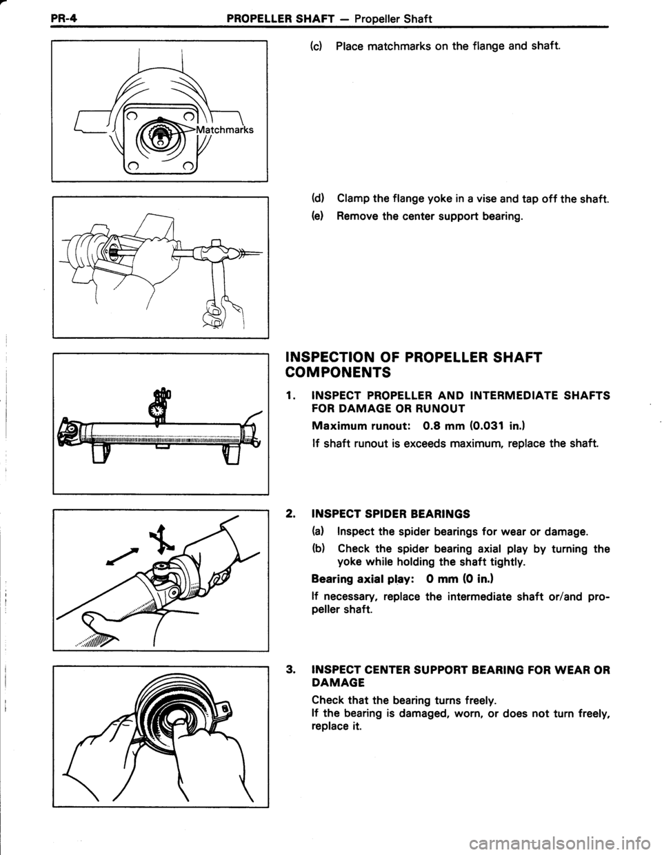
(c) Place matchmarks on the flange and shaft.
(d) Clamp the flange yoke in a vise and tap off the shaft.
(e) Remove the center support bearing.
INSPECTION OF PROPELLER SHAFT
COMPONENTS
1. INSPECT PROPELLER AND INTERMEDIATE SHAFTS
FOR DAMAGE OR RUNOUT
Maximum runout: 0.8 mm (0.031 in.l
lf shaft runout is exceeds maximum, replace the shaft.
2. INSPECT SPIDER BEARINGS
(a) Inspect the spider bearings for wear or damage.
(b) Check the spider bearing axial play by turning the
yoke while holding the shaft tightly.
Bearing axial play: O mm (0 in.l
lf necessary, replace the intermediate shaft orland pro-
peller shaft.
3. INSPECT CENTER SUPPORT BEARING FOR WEAR OR
DAMAGE
Check that the bearing turns freely.
lf the bearing is damaged, worn, or does not turn freely,
replace it.
Page 479 of 885
PROPELLER SHAFT - Propeller ShaftPR.5
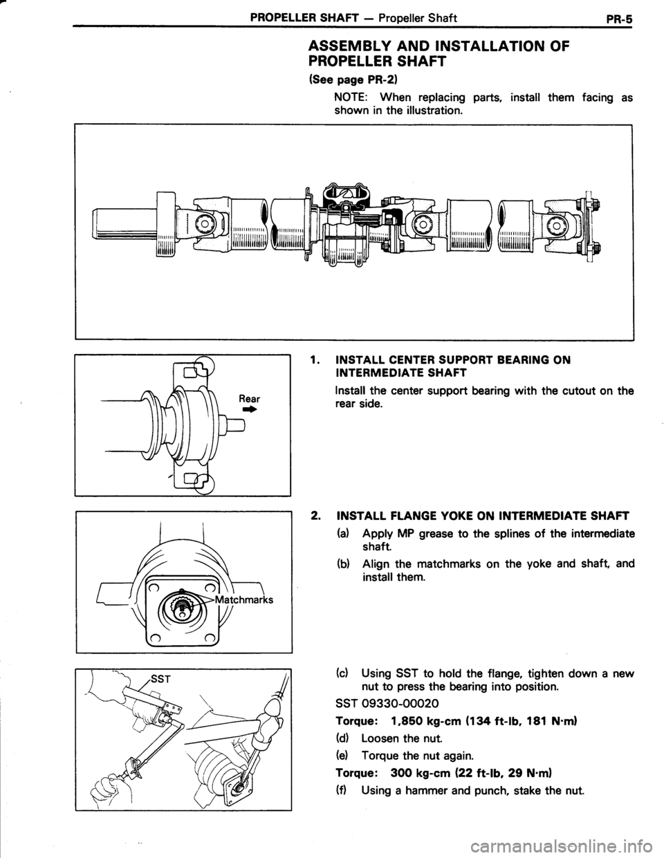
ASSEMBLY AND INSTALLATION OF
PROPELLER SHAFT
(See page PR-21
NOTE: When replacing parts, install them facing as
shown in the illustration.
fl
rthffihP
tuldi€?ih
1. INSTALL CENTER SUPPORT BEARING ON
INTERMEDIATE SHAFT
lnstall the center support bearing with the cutout on the
rear side.
2. INSTALL FTANGE YOKE ON INTERMEDIATE SHAFT
ta) Apply MP grease to the splines of the intermediate
shaft.
(b) Align the matchmarks on the yoke and shaft and
install them.
(c) Using SST to hold the flange, tighten down a
nut to press the bearing into position.
ssT 09330-ooo20
Torque: 1,850 kg-cm (134 ft-lb, 181 N.ml
(d) Loosen the nut.
(e) Torque the nut again.
Torque: 300 kg-cm (22 ft-\b,29 N.ml
(f) Using a hammer and punch, stake the nut.
Page 480 of 885
PR-6 PROPELLER SHAFT - Propeiler Shaft
SST
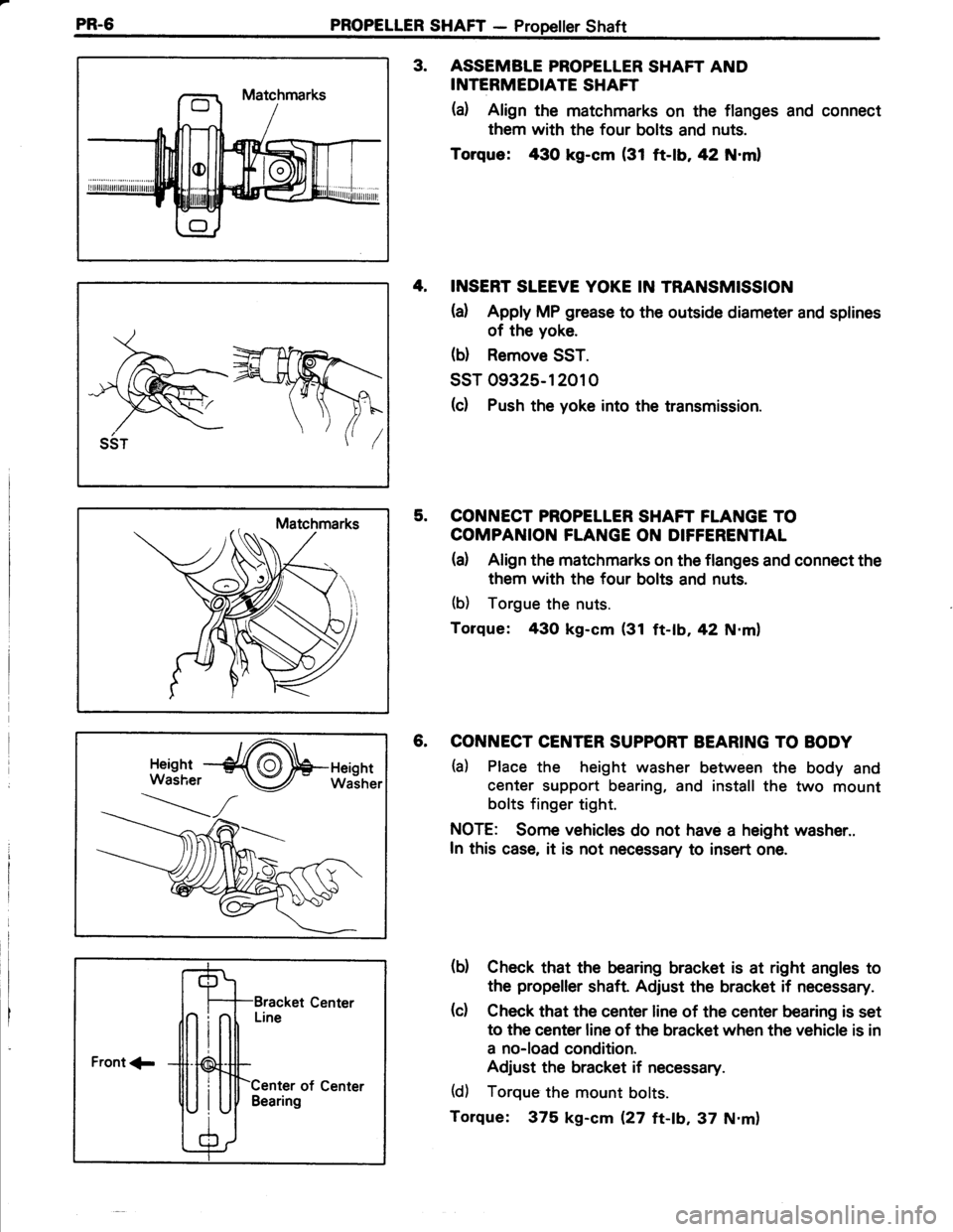
3. ASSEMBTE PROPELLER SHAFT AND
INTERMEDIATE SHAFT
(a) Align the matchmarks on the flanges and connect
them with the four bolts and nuts.
Torque: 430 kg-cm (31 ft-|b,42 N.ml
4, INSERT SLEEVE YOKE IN TRANSMISSION
{a) Apply MP grease to the outsade diameter and splines
of the yoke.
(b) Remove SST.
ssT 09325-12010
(c) Push the yoke into the transmission.
5. CONNECT PROPELLER SHAFT FLANGE TO
COMPANION FLANGE ON DIFFERENTIAL
(a) Align the matchmarks on the flanges and connect the
them with the four bolts and nuts.
(b) Torgue the nuts.
Torque: 43O kg-cm (31 ft-tb,42 N.m)
6. CONNECT CENTER SUPPORT BEARING TO BODY
ta) Place the height washer between the body and
center support bearing, and install the two mount
bolts finger tight.
NOTE: Some vehicles do not have a height washer..
In this case, it is not necessary to insert one.
(b) Check that the bearing bracket is at right angles to
the propeller shaft Adjust the bracket if necessary.
(c) Check that the center line of the center bearing is set
to the center line of the bracket when the vehicle is in
a no-load condition.
Adjust the bracket if necessary.
(d) Torque the mount bolts.
Torque: 375 kg-cm Q7 tt-ab,37 N.m)
Front 1-
Center of CenterBearing
Trending: boot, torque, heater, engine, 4WD, lock, wheel alignment
