TOYOTA TERCEL 1985 Repair Manual
Manufacturer: TOYOTA, Model Year: 1985, Model line: TERCEL, Model: TOYOTA TERCEL 1985Pages: 885, PDF Size: 64.52 MB
Page 561 of 885
BR-2BRAKE SYSTEM - Precautions, Troubleshooting
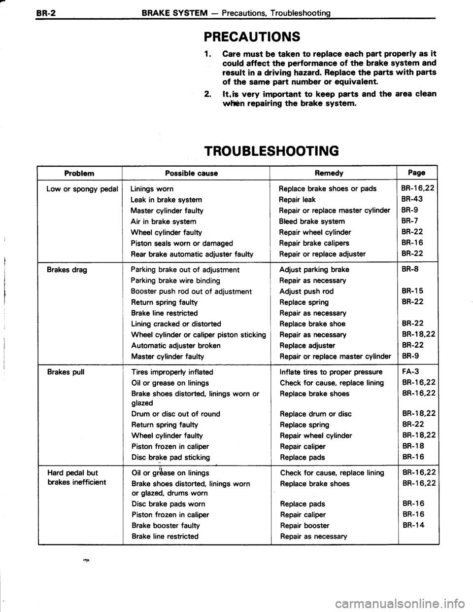
PRECAUTIONS
1. Care must be taken to replace each part properly as it
could affect the performance of the brake system and
result in a driving hazard. Replace the parts with parts
of the same part number or equivalent.
2, ltnis very important to keep parts and the area clean
wltsn repairing the brake system.
TROUBLESHOOTING
ProblemPossible causeRemedyPage
Low or spongy pedalLinings worn
Leak in brake system
Master cylinder faulty
Air in brake system
Wheel cylinder faulty
Piston seals worn or damaged
Rear brake automatic adiuster faulty
Replace brake shoes or pads
Repair leak
Repair or replace master cylinder
Bleed brake system
Repair wheel cylinder
Repair brake calipers
Repair or replace adjuster
BR-16,22
BR-43
BR-9
BR-7
8R.22
BR-1 6
B,R.22
Brakes dragParking brake out of adjustment
Parking brake wire binding
Booster push rod out of adjustment
Return spring faulty
Brake line restricted
Lining cracked or distorted
Wheel cylinder or caliper piston sticking
Automatic adjuster broken
Master cylinder faulty
Adjust parking brake
Repair as necessary
Adjust push rod
Replace spring
Repair as necessary
Replace brake shoe
Repair as necessary
Replace adjuster
Repair or replace master cylinder
BR.8
BR.1 5
BR-22
BR-22
BR-18,22
BR-22
BR-9
Brakes pullTires improperly inflated
Oil or grease on linings
Brake shoes distorted, linings worn or
glazed
Drum or disc out of round
Return spring faulty
Wheel cylinder faulty
Piston frozen in caliper
Disc brake pad sticking
Inflate tires to proper pressure
Check for cause, replace lining
Replace brake shoes
Replace drum or disc
Replace spring
Repair wheel cylinder
Repair caliper
Replace pads
FA-3
BR-16,22
BR-16,22
BR-l8,22
BR-22
BR-18,22
BR.1 8
BR-1 6
Hard pedal but
brakes inefficient
Oil or grbase on linings
Brake shoes distorted, linings worn
or glazed, drums worn
Disc brake pads worn
Piston frozen in caliper
Brake booster faulty
Brake line restricted
Check for cause, replace lining
Replace brake shoes
Replace pads
Repair caliper
Repair booster
Repair as necessary
BR-I6,22
BR-16,22
BR-1 6
BR-1 6
BR.1 4
Page 562 of 885
BRAKE SYSTEM - TroubleshootingBR.3
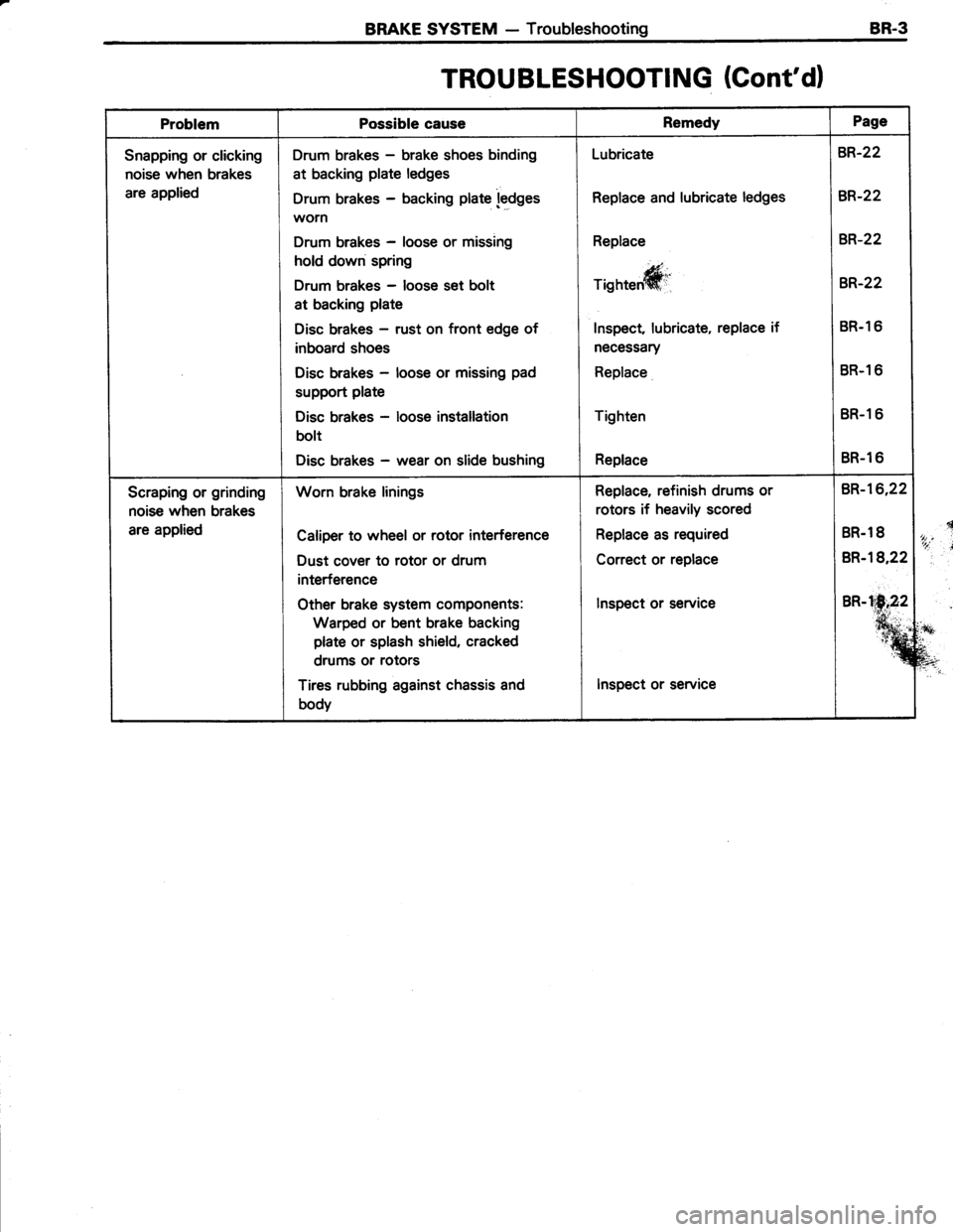
TROU BLESHOOTING (Cont'd)
ProblemPossible causeRemedyPage
r+i
:?*
a?"t
Snapping or clicking
noise when brakes
are applied
Drum brakes - brake shoes binding
at backing plate ledges
Drum brakes - backing plate ledgesworn
Drum brakes - loose or missing
hold down spring
Drum brakes - loose set bolt
at backing plate
Disc brakes - rust on front edge of
inboard shoes
Disc brakes - loose or missing pad
support plate
Disc brakes - loose installation
bolt
Disc brakes - wear on slide bushing
Lubricate
Replace and lubricate ledges
Replace
E,
Tisnteffit'
Inspect lubricate, replace if
necessary
Replace
Tighten
Replace
BR-22
BR-22
BR-22
BR-22
BR.1 6
BR-1 6
BR-1 6
BR-1 6
Scraping or grinding
noise when brakes
are applied
Worn brake linings
Caliper to wheel or rotor interference
Dust cover to rotor or drum
interference
other brake system components:
Warped or bent brake backing
plate or splash shield, cracked
drums or rotors
Tires rubbing against chassis and
body
Replace, refinish drums or
rotors if heavily scored
Replace as required
Correct or replace
lnspect or service
Inspect or service
BR-16,22
BR.1 8
BR-l8,22
BR-h1N,22
%
Page 563 of 885
BR-4 BRAKE SYSTEM - Troubleshooting
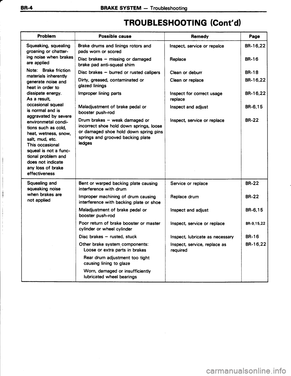
TROU BLESHOOTI NG (Cont'd)
ProblemPossible causeRemedyPage
Squeaking, squealing
groaning or chatter-
ing noise when brakes
are applied
Note: Brake friction
materials inherently
generate noise and
heat in order to
dissipate energy.
As a result
occasional squeal
is normaland is
aggravated by severe
environmetal condi-
tions such as cold,
heat, wetness, snow,
salt mud, etc.
This occasional
squeal is not a func-
tional problem and
does not indicate
any loss of brake
effectiveness
Brake drums and linings rotors and
pads worn or scored
Disc brakes - missing or damaged
brake pad anti-squeal shim
Disc brakes - burred or rusted calipers
Dirty, greased, contaminated or
glazed linings
lmproper lining parts
Maladjustment of brake pedal or
booster push-rod
Drum brakes - weak damaged or
incorrect shoe hold down springs, loose
or damaged shoe hold down spring pins
springs and grooved backing plate
ledges
Inspect, service or repalce
Replace
Clean or deburr
Clean or replace
Inspect for conect usage
replace
lnspect and adjust
Inspect service or replace
BR-16,22
BR.l 6
BR-1 8
BR-16,22
BR-'�t6,22
BR-6,15
8R.22
Squealing and
squeaking noise
when brakes are
not applied
Bent or warped backing plate causing
interference with drum
lmproper machining of drum causing
interference with backing plate or shoe
Maladjustment of brake pedal or
booster push-rod
Poor return of brake booster or master
cylinder or wheel cylinder
Disc brakes - rusted, stuck
Other brake system, components:
Loose or extra parts in brakes
Rear drum adjustment too tight
causing lining to glaze
Worn, damaged or insufficiently
lubricated wheel bearings
Service or replace
Replace drum
Inspect and adjust
Inspect, service or replace
Inspect lubricate as necessary
Inspect, service, replace as
required
BR-22
8R.22
BR-6,15
BR-g,15,22
BR.1 6
BR-16,22
Page 564 of 885
BRAKE SYSTEM - TroubleshootingBR-5
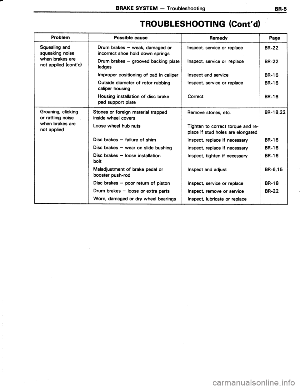
TROUBLESHOOTING (Cont'dl
ProblemPossible causeRemedyPage
Squealing and
squeaking noise
when brakes are
not applied (cont'd)
Drum brakes - weak, damaged or
incorrect shoe hold down springs
Drum brakes - grooved backing plate
ledges
lmproper positioning of pad in caliper
Outside diameter of rotor rubbing
caliper housing
Housing installation of disc brake
pad support plate
Inspect, service or replace
Inspect, service or replace
Inspect and service
Inspect, service or replace
Correct
BR-22
BR-22
BR-l 6
BR-l 6
BR-1 6
Groaning, clicking
or rattling noise
when brakes are
not applied
Stones or foreign material trapped
inside wheel covers
Loose wheel hub nuts
Disc brakes - failure of shim
Disc brakes - wear on slide bushing
Disc brakes - loose installation
bolt
Maladjustment of brake pedal or
booster push-rod
Disc brakes - poor return of piston
Drum brakes - loose or extra parts
Worn, damaged or dry wheel bearings
Remove stones, etc.
Tighten to correct torque and re-
place if stud holes are elongated
lnspect, replace if necessary
Inspect, replace if necessary
Inspect, tighten if necessary
lnspect and adjust
Inspect, service or replace
Inspect remove or service
lnspect lubricate or replace
BR-18,22
BR.1 6
BR.1 6
BR-1 6
BR-6,15
BR.1 8
B,R.22
Page 565 of 885
Stop Light Switch
Pedal Push Rod
Pedal Freeplay
Asphalt SheetPedat Height
BRAKE SYSTEM - Checks and
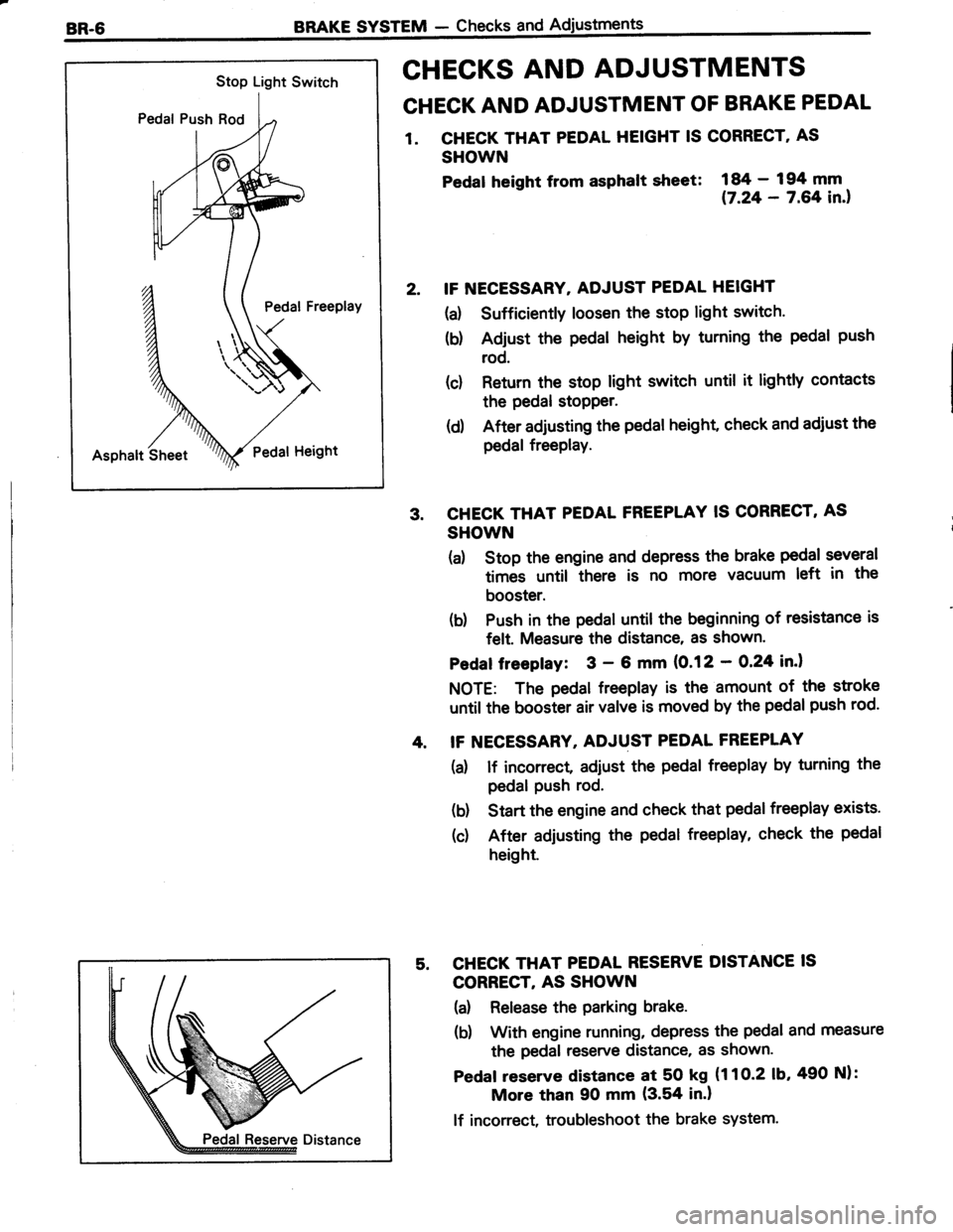
CHECKS AND ADJUSTMENTS
CHECK AND ADJUSTMENT OF BRAKE PEDAL
1. CHECK THAT PEDAL HEIGHT IS CORRECT' AS
SHOWN
Pedat heisht from asphalt slreet:
i#;:?ifil.,
IF NECESSARY. ADJUST PEDAL HEIGHT
(a) Sufficiently loosen the stop light switch.
(b) Adjust the pedal height by turning the pedal push
rod.
(c) Return the stop light switch until it lightly contacts
the pedal stopper.
(d) After adjusting the pedal height, check and adiust the
pedal freePlay.
CHECK THAT PEDAL FREEPLAY IS CORRECT, AS
SHOWN
(a) Stop the engine and depress the brake pedal several
times until there is no more vacuum left in the
booster.
(b) Push in the pedal until the beginning of resistance is
felt. Measure the distance, as shown'
Pedaf freepfay: 3 - 6 mm (0.12 - O,24 in.l
NOTE: The pedal freeplay is the amount of the stroke
until the booster air valve is moved by the pedal push rod.
IF NECESSARY, ADJUST PEDAL FREEPLAY
(a) lf incorrect adiust the pedal freeplay by turning the
pedal Push rod.
(b) Start the engine and check that pedal freeplay exists.
(c) After adjusting the pedal freeplay, check the pedal
height.
CHECK THAT PEDAL RESERVE DISTANCE IS
CORRECT, AS SHOWN
(a) Release the parking brake.
(b) With engine running, depress the pedal and measure
the pedal reserve distance, as shown.
Pedaf reserve distance at 50 kg (1 1 O-2 1b,490 Nl:
More than 90 mm (3.54 in.l
lf incorrect, troubleshoot the brake system.
Page 566 of 885
BRAKE SYSTEM - Checks and AdjustmentsBR-7
@@
VV
1 st 2nd
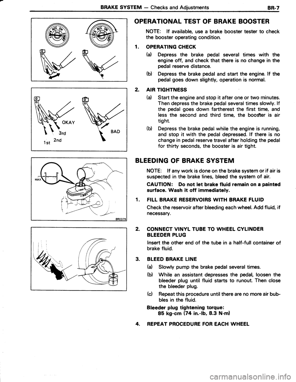
OPERATIONAL TEST OF BRAKE BOOSTER
NOTE: lf available, use a brake booster tester to check
the booster operating condition.
1. OPERATING CHECK
(a) Depress the brake pedal several times with the
engine off, and check that there is no change in the
pedal reserve distance.
(b) Depress the brake pedal and start the engine. lf the
pedal goes down slightly, operation is normal.
2. AIR TIGHTNESS
(d Start the engine and stop it after one or two minutes.
Then depress the brake pedal several times slowly. lf
the pedal goes down fartherest the first time, and
less the second and third time, the boo$ter is air
tight.
(b) Depress the brake pedal while the engine is running,
and stop it with the pedal depressed. lf there is no
change in pedal reserve travel after holding the pedal
for thirty seconds, the booster is air tight.
BLEEDING OF BRAKE SYSTEM
NOTE: lf any work is done on the brake system or if air is
suspected in the brake lines, bleed the system of air.
CAUTION: Do not let brake fluid remain on a painted
surface. Wash it off immediataly.
1. FILL BRAKE RESERVOIRS WITH BRAKE FLUID
Check the reservoir after bleeding each wheel. Add fluid, if
necessary.
2, CONNECT VINYL TUBE TO WHEEL CYLINDER
BLEEDER PLUG
lnsert the other end of the tube in a half-full container of
brake fluid.
3. BLEED BRAKE LINE
(a) Slowly pump the brake pedal several times.
(b) While an assistant depresses the pedal, loosen the
bleeder plug until fluid starts to runout. Then close
the bleeder plug.
(c) Repeat this procedure until there are no more air bub-
bles in the fluid.
Bleeder plug tightening torque:
85 kg-cm (74 in.-lb,8.3 N.m)
4. REPEAT PROCEDURE FOR EACH WHEEL
Page 567 of 885
BR.8BRAKE SYSTEM - Checks and Adjustments
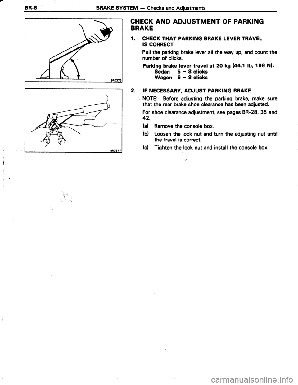
CHECK AND ADJUSTMENT OF PARKING
BRAKE
1. CHECK THAT PARKING BRAKE LEVER TRAVEL
IS CORRECT
Pull the parking brake lever all the way up, and count the
number of clicks.
Parking brake lever travel at 2O kg (44.1 lb, 196 Nl:
Sedan 5-Sclicks
Wagon 6-Sclicks
2. IF NECESSARY, ADJUST PARKING BRAKE
NOTE: Before adjusting the parking brake, make sure
that the rear brake shoe clearance has been adjusted.
For shoe clearance adjustment, see pages BR-28, 35 and
42.
(a) Remove the console box.
(d Loosen the lock nut and turn the adjusting nut until
the travel is correct.
(d Tighten the lock nut and install the console box.
*r .;"
Page 568 of 885
BRAKE SYSTEM - Master CylinderBR-9
MASTER CYLINDER
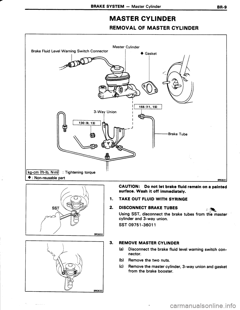
REMOVAL OF MASTER CYLINDER
Master Cylinder
Brake Fluid LevelWarning Switch Connectort) Gasket
I
I
s
Brake Tube
-cm (ft-lb,
O: Non-reusable part
1s5 (1 1, 15)
Tightening torque
GAUTION: Do not let brake fluid remain on a painted
surface. Wash it off immediatoly.
1. TAKE OUT FLUID WITH SYRINGE
2. DISCONNECT BRAKE TUBES j ,�.
Usin! SST, disconnect the brake tubes from tfie master
cylinder and 3-way union.
ssT 09751-3601 1
3. REMOVE MASTER CYLINDER
(d Disconnect the brake fluid level warning switch con-
nector.
(b) Remove the two nuts.
(c) Remove the master cylinder, 3-way union and gasket
from the brake booster.
Page 569 of 885
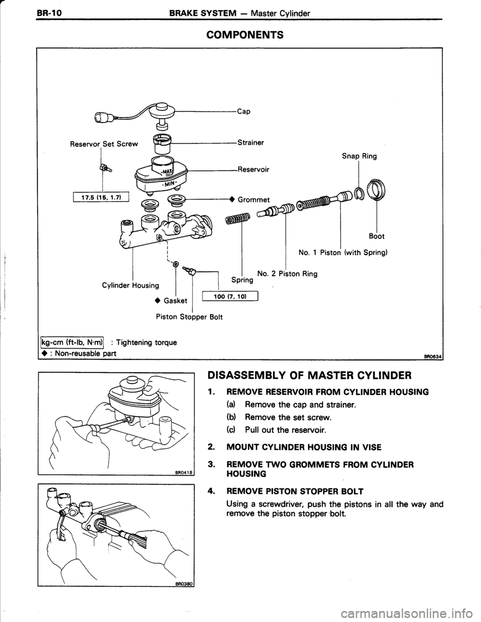
aBR.lOBRAKE SYSTEM - Master Cylinder
COMPONENTS
Reservor Set Screw
I
F(
Ir
I rzt{rtaz-l
%-Reservoir
I
9-.o
RN ry'jbTry^?
Snap Ring
}N ryofltort""* | |-+)rlllsciot
| |
*" 1 Piston (with SPring)
\p-l ^l No.2pistonRins
I I uprrng
-^ I I roo tz, rot Ierl
(ft-rb, N
O : Non-reusable part
Piston Stopper Bolt
: Tightening torque
O Gasket
DISASSEMBLY OF MASTER CYLINDER
1. REMOVE RESERVOIR FROM CYLINDER HOUSING
(a) Remove the cap and strainer.
(d Remove the set screw.
(c) Pull out the reservoir.
2. MOUNT CYLINDER HOUSING IN VISE
3. REMOVE TWO GROMMETS FROM CYLINDER
HOUSING
4. REMOVE PISTON STOPPER BOLT
Using a screwdriver, push the pistons in all the way and
remove the piston stopper'bolt.
Page 570 of 885
BRAKE SYSTEM - Master CylinderBR-11
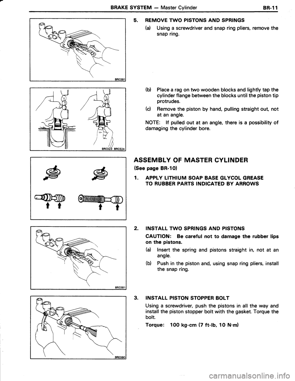
5. REMOVE TWO PISTONS AND SPRINGS
(d Using a screwdriver and snap ring pliers, remove the
snap ring.
(b) Place a rag on two wooden blocks and lightly tap the
cylinder flange between the blocks until the piston tip
protrudes.
(c) Remove the piston by hand, pulling straight out, not
at an angle.
NOTE: lf pulled out at an angle, there is a possibility of
damaging the cylinder bore.
ASSEMBLY OF MASTER CYLINDER
(See page BR-10)
1. APPLY LITHIUM SOAP BASE GLYCOL GREASE
TO RUBBER PARTS INDICATED BY ARROWS
2. INSTALL TWO SPRINGS AND PISTONS
CAUTION: Be careful not to damage the rubber lips
on the pistons.
(d lnsert the spring and pistons straight in, not at an
angle.
(b) Push in the piston and, using snap ring pliers, install
the snap ring.
INSTALL PISTON STOPPER BOLT
Using a screwdriver, push the pistons in all the way and
install the piston stopper bolt with the gasket. Torque the
bolt.
Torque: 100 kg-cm (7 ft-lb, 1O N.m)
.g
G@D
tr
.g
OnmmU=$
rt
3.