VOLKSWAGEN CORRADO 1993 Repair Manual
Manufacturer: VOLKSWAGEN, Model Year: 1993, Model line: CORRADO, Model: VOLKSWAGEN CORRADO 1993Pages: 920, PDF Size: 6.92 MB
Page 431 of 920

B - EMISSION APPLICATION
Article Text (p. 2)
1993 Volkswagen Corrado
For Volkswagen Technical Site: http://vw.belcom.ru
Copyright © 1998 Mitchell Repair Information Company, LLC
Wednesday, March 22, 2000 08:57PM
2.0L 4-Cyl. CIS-E Motronic
Major Control Systems & Devices ............. PCV, EVAP, TWC, FR,
(2) EGR, SPK, AP,
(1) O2, CEC, (2) MIL
Components & Other Related Devices ........ (4) EVAP-PV, EVAP-CV,
EGR-VA, EGR-TVV, SPK-CC
2.8L VR6 Motronic MFI
Major Control Systems & Devices ........ PCV, EVAP, TWC, FR, EGR,
SPK, AP, (1) O2, CEC, (2) MIL
Components & Other Related Devices ...... AP-EAP, AP-ERLY, AP-SV,
AP-SOV, EVAP-PV, EVAP-VC,
EGR-CV, EGR-TS, SPK-CC
(1) - Heated O2 sensor.
(2) - California only.
(3) - Digifant II only.
(4) - Two required.ÄÄÄÄÄÄÄÄÄÄÄÄÄÄÄÄÄÄÄÄÄÄÄÄÄÄÄÄÄÄÄÄÄÄÄÄÄÄÄÄÄÄÄÄÄÄÄÄÄÄÄÄÄÄÄÄÄÄÄÄÄÄÄÄÄÄÄÄÄÄ ABBREVIATION DEFINITIONS
ABBREVIATION DEFINITION TABLE
ÄÄÄÄÄÄÄÄÄÄÄÄÄÄÄÄÄÄÄÄÄÄÄÄÄÄÄÄÄÄÄÄÄÄÄÄÄÄÄÄÄÄÄÄÄÄÄÄÄÄÄÄÄÄÄÄÄÄÄÄAbbreviation Definition
AP ............................. Air Pump Injection System
AP-EAP .............................. AP Electric Air Pump
AP-ERLY ....................... AP Electric Air Pump Relay
AP-SV .......................... AP Solenoid (Inlet) Valve
AP-SOV ................................. AP Shut Off Valve
CEC ......................... Computerized Engine Controls
EGR ............................ Exhaust Gas Recirculation
EGR-CV ..................... EGR Control (Frequency) Valve
EGR-TS ............................ EGR Temperature Sensor
EGR-TVV ......................... EGR Thermal Vacuum Valve
EGR-VA .............................. EGR Vacuum Amplifier
EVAP ............................. Fuel Evaporative System
EVAP-CS ............................ EVAP Control Solenoid
EVAP-PV ................................. EVAP Purge Valve
EVAP-VC .............................. EVAP Vapor Canister
FR .................................. Fill Pipe Restrictor
HAI ....................................... Hot Air Intake
MIL ........... Malfunction Indicator (CHECK ENGINE) Light
MFI ............................. Multiport Fuel Injection
O2 ......................................... Oxygen Sensor
PCV ....................... Positive Crankcase Ventilation
SPK ................................. Spark Control System
SPK-CC ........................... SPK Computer Controlled
TWC ................................... Three-Way Catalyst
ÄÄÄÄÄÄÄÄÄÄÄÄÄÄÄÄÄÄÄÄÄÄÄÄÄÄÄÄÄÄÄÄÄÄÄÄÄÄÄÄÄÄÄÄÄÄÄÄÄÄÄÄÄÄÄÄÄÄÄÄEND OF ARTICLE
Page 432 of 920

BRAKE SYSTEM
Article Text
1993 Volkswagen Corrado
For Volkswagen Technical Site: http://vw.belcom.ru
Copyright © 1998 Mitchell Repair Information Company, LLC
Wednesday, March 22, 2000 08:57PM
ARTICLE BEGINNING
1992-93 BRAKES
Volkswagen Disc & Drum
Corrado SLC
DESCRIPTION
All models are equipped with front disc brakes. Rear brakes
are either disc or drum. Parking brake acts on rear brakes and is
cable-actuated. All models use pressure regulator between front and
rear brake circuits to avoid rear wheel lock-up during hard braking.
A vacuum power-assist servo is used to ease brake pedal
application. A vacuum check valve, located in vacuum supply hose,
prevents vacuum leakdown when engine is off.
SERVICING
Manufacturer recommends replacing brake fluid every 2 years.
BLEEDING BRAKE SYSTEM
CAUTION: Ensure fluid level in master cylinder is adequate at all
times during bleeding procedure. Use only DOT 4 brake fluid.
DO NOT use DOT 5 silicone brake fluid.
BLEEDING PROCEDURES
NOTE: Manufacturer recommends bleeding brake system using Pressure
Bleeder (US 1116). If a pressure bleeder is not available,
use standard bleeding procedure.
1) Exhaust vacuum reserve from power unit by depressing brake
pedal several times. On ABS-equipped vehicles, depress brake pedal at
least 20 times to relieve system pressure.
2) On all vehicles, fill master cylinder with clean brake
fluid. If master cylinder was replaced, bleed master cylinder before
bleeding wheel calipers. Connect bleeder hose to appropriate caliper
bleeder valve. See BRAKE BLEEDING SEQUENCE table.
BRAKE BLEEDING SEQUENCE TABLEÄÄÄÄÄÄÄÄÄÄÄÄÄÄÄÄÄÄÄÄÄÄÄÄÄÄÄÄÄÄÄÄÄÄÄÄÄÄÄÄÄÄÄÄÄÄÄÄÄÄÄÄÄÄÄÄÄÄÄÄApplication (1) Sequence
Corrado SLC .................. Either Front Caliper First,
Either Rear Caliper First
(1) - Push lever of pressure regulator in direction of rear
axle when bleeding rear brakes.
ÄÄÄÄÄÄÄÄÄÄÄÄÄÄÄÄÄÄÄÄÄÄÄÄÄÄÄÄÄÄÄÄÄÄÄÄÄÄÄÄÄÄÄÄÄÄÄÄÄÄÄÄÄÄÄÄÄÄÄÄ
Page 433 of 920

BRAKE SYSTEM
Article Text (p. 2)
1993 Volkswagen Corrado
For Volkswagen Technical Site: http://vw.belcom.ru
Copyright © 1998 Mitchell Repair Information Company, LLC
Wednesday, March 22, 2000 08:57PM
3) Submerge other end of hose in clean glass jar partially
filled with clean brake fluid. Pump brake pedal several times, then
hold down. Open bleeder valve. Holding pedal down, close bleeder
valve. Release brake pedal.
4) Repeat procedure until brake fluid shows no signs of air
bubbles. When bleeding rear brakes, push lever of pressure regulator
in direction of rear axle.
5) After bleeding ABS vehicles, turn ignition on. Allow pump
to run until it shuts off. If pump runs longer than 2 minutes, allow
pump to cool for 10 minutes. On all vehicles, ensure master cylinder
reservoir is full.
ADJUSTMENTS
BRAKE PRESSURE REGULATOR
CAUTION: DO NOT adjust pressure regulator with brake pedal depressed.
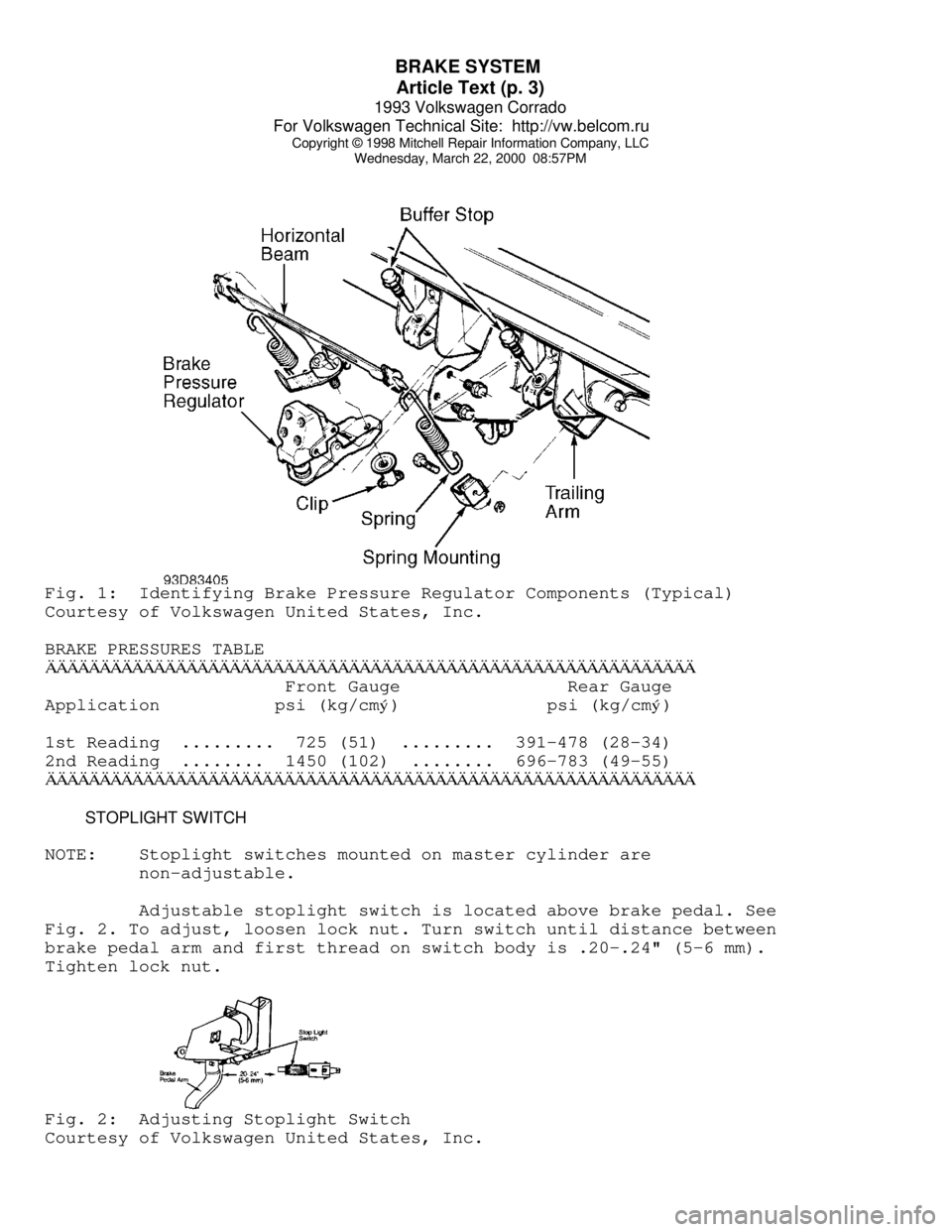
1) Depress brake pedal once firmly. Release brake pedal
quickly, watching for regulator lever to move when pedal is released.
If regulator lever does not move when pedal is released, replace
regulator. If regulator lever moved, go to next step.
2) Ensure vehicle fuel tank is full, luggage compartment is
empty and a driver is in driver seat. Raise and support vehicle. Using
Pressure Gauges (US 1016), attach one gauge to right rear brake
cylinder or caliper. If vehicle is ABS-equipped, go to next step. If
vehicle is not ABS-equipped, go to step 4).
3) Using Distributor "T" (803 611 755) and an additional 8"
(203 mm) of brakeline, connect one gauge in front of pressure
regulator. Bleed pressure gauge and hoses through valve on gauges.
Lower vehicle. Bounce rear of vehicle several times. Go to step 5).
4) Attach Pressure Gauges (US 1016) to left front brake
caliper. Bleed pressure gauge and hoses through valve on gauges. Lower
vehicle. Bounce rear of vehicle several times.
5) Pump brake pedal several times. Press on brake pedal until
reading on front gauge shows pressure given for first reading in the
BRAKE PRESSURES table. Hold brake pressure to specification. Rear
gauge reading should be within specification given for first reading
in the BRAKE PRESSURES table.
6) Increase pressure on brake pedal until reading on front
gauge shows pressure given for second reading in the BRAKE PRESSURES
table. Hold brake pressure to specification. Rear gauge reading should
be within specification given for second reading in BRAKE PRESSURES
table. If pressures are within specification, brake pressure regulator
is functioning properly. If pressures are not within specification, go
to next step.
7) If pressure is too high, decrease spring pressure on
regulator. If pressure is too low, increase spring pressure on
regulator. If adjusting spring pressure on regulator does not bring
pressures within specification, replace pressure regulator. Disconnect
gauges, and bleed brakes.
Page 434 of 920

BRAKE SYSTEM
Article Text (p. 3)
1993 Volkswagen Corrado
For Volkswagen Technical Site: http://vw.belcom.ru
Copyright © 1998 Mitchell Repair Information Company, LLC
Wednesday, March 22, 2000 08:57PMFig. 1: Identifying Brake Pressure Regulator Components (Typical)
Courtesy of Volkswagen United States, Inc.
BRAKE PRESSURES TABLEÄÄÄÄÄÄÄÄÄÄÄÄÄÄÄÄÄÄÄÄÄÄÄÄÄÄÄÄÄÄÄÄÄÄÄÄÄÄÄÄÄÄÄÄÄÄÄÄÄÄÄÄÄÄÄÄÄÄÄÄ Front Gauge Rear Gauge
Application psi (kg/cm
ý) psi (kg/cmý)
1st Reading ......... 725 (51) ......... 391-478 (28-34)
2nd Reading ........ 1450 (102) ........ 696-783 (49-55)
ÄÄÄÄÄÄÄÄÄÄÄÄÄÄÄÄÄÄÄÄÄÄÄÄÄÄÄÄÄÄÄÄÄÄÄÄÄÄÄÄÄÄÄÄÄÄÄÄÄÄÄÄÄÄÄÄÄÄÄÄ STOPLIGHT SWITCH
NOTE: Stoplight switches mounted on master cylinder are
non-adjustable.
Adjustable stoplight switch is located above brake pedal. See
Fig. 2. To adjust, loosen lock nut. Turn switch until distance between
brake pedal arm and first thread on switch body is .20-.24" (5-6 mm).
Tighten lock nut.Fig. 2: Adjusting Stoplight Switch
Courtesy of Volkswagen United States, Inc.
Page 435 of 920

BRAKE SYSTEM
Article Text (p. 4)
1993 Volkswagen Corrado
For Volkswagen Technical Site: http://vw.belcom.ru
Copyright © 1998 Mitchell Repair Information Company, LLC
Wednesday, March 22, 2000 08:57PM
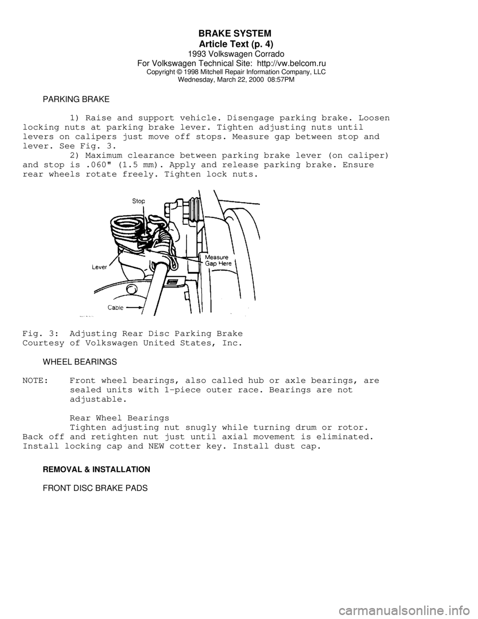
PARKING BRAKE
1) Raise and support vehicle. Disengage parking brake. Loosen
locking nuts at parking brake lever. Tighten adjusting nuts until
levers on calipers just move off stops. Measure gap between stop and
lever. See Fig. 3.
2) Maximum clearance between parking brake lever (on caliper)
and stop is .060" (1.5 mm). Apply and release parking brake. Ensure
rear wheels rotate freely. Tighten lock nuts.Fig. 3: Adjusting Rear Disc Parking Brake
Courtesy of Volkswagen United States, Inc.
WHEEL BEARINGS
NOTE: Front wheel bearings, also called hub or axle bearings, are
sealed units with 1-piece outer race. Bearings are not
adjustable.
Rear Wheel Bearings
Tighten adjusting nut snugly while turning drum or rotor.
Back off and retighten nut just until axial movement is eliminated.
Install locking cap and NEW cotter key. Install dust cap.
REMOVAL & INSTALLATION
FRONT DISC BRAKE PADS
Page 436 of 920

BRAKE SYSTEM
Article Text (p. 5)
1993 Volkswagen Corrado
For Volkswagen Technical Site: http://vw.belcom.ru
Copyright © 1998 Mitchell Repair Information Company, LLC
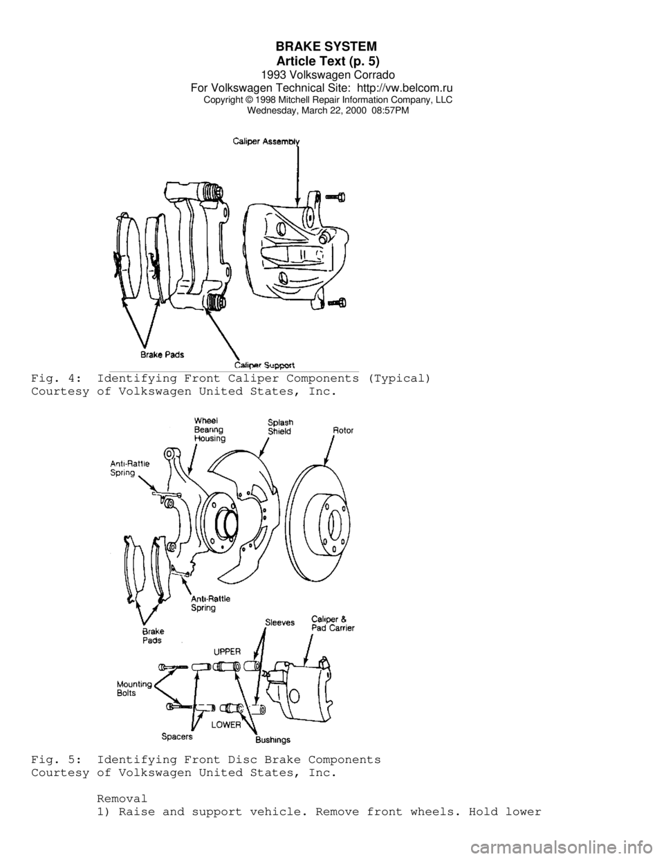
Wednesday, March 22, 2000 08:57PMFig. 4: Identifying Front Caliper Components (Typical)
Courtesy of Volkswagen United States, Inc.Fig. 5: Identifying Front Disc Brake Components
Courtesy of Volkswagen United States, Inc.
Removal
1) Raise and support vehicle. Remove front wheels. Hold lower
Page 437 of 920

BRAKE SYSTEM
Article Text (p. 6)
1993 Volkswagen Corrado
For Volkswagen Technical Site: http://vw.belcom.ru
Copyright © 1998 Mitchell Repair Information Company, LLC
Wednesday, March 22, 2000 08:57PM
guide pin using an open end wrench. Remove lower caliper mounting
bolt. Push caliper assembly upward and swing out from bottom.
2) Siphon small amount of brake fluid from reservoir. Remove
pads and retaining springs from caliper support. Replace pads
exceeding wear limit. Wear limit of pads is .28" (7.0 mm), including
backing plate. See Fig. 4 or 5.
Installation
1) Seat caliper piston fully into cylinder bore. Install
inner pad and then outer pad. Swing caliper assembly down. Hold lower
guide pin using an open end wrench.
2) Install lower caliper mounting bolt. Depress brake pedal
several times to allow pads to move into operating position. Ensure
master cylinder reservoir fluid level is full.
FRONT & REAR BRAKE CALIPER
Removal & Installation
1) Raise and support vehicle. Remove wheels. Disconnect
brakeline from caliper, and plug openings. Bend back locking tabs (if
equipped) on mounting bolts. If removing rear brake calipers,
disconnect parking brake cables.
2) On all calipers, remove caliper mounting bolts. See Fig. 4
or 6. Remove caliper assembly from wheel bearing housing. To install,
reverse removal procedure. Use NEW lock plates (if equipped) and
mounting bolts. Bleed hydraulic brake system. See BLEEDING PROCEDURES
under BLEEDING BRAKE SYSTEM.
FRONT & REAR BRAKE ROTOR
Removal
Raise and support vehicle. Remove wheels. Remove caliper and
suspend from frame with wire. Remove countersunk screw that holds
rotor to hub. Pull rotor off hub.
Installation
To install, reverse removal procedure. Adjust wheel bearings
(if necessary). See WHEEL BEARINGS under ADJUSTMENTS.
REAR DISC BRAKE PADS
Removal
Raise and support vehicle. Remove rear wheels. Disconnect
parking brake cable from caliper. Remove caliper mounting bolts.
Remove caliper and wire aside. Siphon small amount of brake fluid from
reservoir. Remove pads and retaining springs from caliper support.
Replace pads that exceed wear limit. Wear limit of pads is .28" (7.0
mm), including backing plate.
Installation
Seat caliper piston fully into cylinder bore. Install inner
pad first and then install outer pad. Position caliper. Install
Page 438 of 920

BRAKE SYSTEM
Article Text (p. 7)
1993 Volkswagen Corrado
For Volkswagen Technical Site: http://vw.belcom.ru
Copyright © 1998 Mitchell Repair Information Company, LLC
Wednesday, March 22, 2000 08:57PM
caliper mounting bolts. Depress brake pedal several times to allow
pads to move into operating position. Ensure master cylinder reservoir
fluid level is full.
MASTER CYLINDER
Removal
1) Drain master cylinder reservoir. Remove cover plate (if
equipped). Disconnect brakelines and wiring at master cylinder.
2) On models without power assist servo, disconnect brake
push rod at brake pedal. On models equipped with power assist servo,
remove master cylinder from servo. Be careful to keep any spacers used
on attaching bolts for proper installation.
Installation
To install, reverse removal procedure. Always use NEW "O"
ring between master cylinder and power assist servo. Bleed hydraulic
system.
VACUUM POWER ASSIST SERVO
Removal
Remove master cylinder from power assist servo. Disconnect
brake push rod from brake pedal. Disconnect vacuum hose from servo.
Remove servo from vehicle.
NOTE: Not all vehicles have all components.
Installation
To install, reverse removal procedure. Before attaching brake
push rod to brake pedal, check and adjust push rod length. Always use
NEW damping ring, washer, filter and "O" ring (as equipped). Slots in
damping washer and filter must be offset 180 degrees (if equipped).
Complete installation, and bleed hydraulic system.
OVERHAUL
NOTE: Black staining from piston seal wear may show on caliper
bore walls and piston. This staining is normal. DO NOT
disassemble power assist servo as parts are not available.
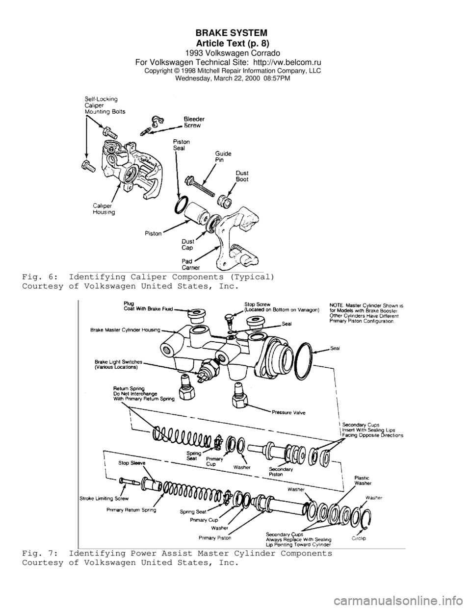
Refer to appropriate illustration for caliper and master
cylinder overhaul. See Figs. 6 and 7.
Page 439 of 920

BRAKE SYSTEM
Article Text (p. 8)
1993 Volkswagen Corrado
For Volkswagen Technical Site: http://vw.belcom.ru
Copyright © 1998 Mitchell Repair Information Company, LLC
Wednesday, March 22, 2000 08:57PMFig. 6: Identifying Caliper Components (Typical)
Courtesy of Volkswagen United States, Inc.Fig. 7: Identifying Power Assist Master Cylinder Components
Courtesy of Volkswagen United States, Inc.
Page 440 of 920

BRAKE SYSTEM
Article Text (p. 9)
1993 Volkswagen Corrado
For Volkswagen Technical Site: http://vw.belcom.ru
Copyright © 1998 Mitchell Repair Information Company, LLC
Wednesday, March 22, 2000 08:57PM
TORQUE SPECIFICATIONS
TORQUE SPECIFICATIONS TABLEÄÄÄÄÄÄÄÄÄÄÄÄÄÄÄÄÄÄÄÄÄÄÄÄÄÄÄÄÄÄÄÄÄÄÄÄÄÄÄÄÄÄÄÄÄÄÄÄÄÄÄÄÄÄÄÄÄÄÄÄApplication Ft. Lbs. (N.m)
Caliper Mounting Bolts (1) ........................ 26 (35)
Pad Carrier Mounting Bolt
Front .......................................... 92 (125)
Rear ............................................ 48 (65)
Rear Backing Plate-To-Flange Bolt ................ 44 (60)
Wheel Lug Nut .................................... 81 (110)
INCH Lbs. (N.m)
Wheel Cylinder Bolt ............................... 80 (9)
(1) - Always replace all self-locking bolts.
ÄÄÄÄÄÄÄÄÄÄÄÄÄÄÄÄÄÄÄÄÄÄÄÄÄÄÄÄÄÄÄÄÄÄÄÄÄÄÄÄÄÄÄÄÄÄÄÄÄÄÄÄÄÄÄÄÄÄÄÄ DISC BRAKE SPECIFICATIONS
DISC BRAKE SPECIFICATIONS TABLE (1)
ÄÄÄÄÄÄÄÄÄÄÄÄÄÄÄÄÄÄÄÄÄÄÄÄÄÄÄÄÄÄÄÄÄÄÄÄÄÄÄÄÄÄÄÄÄÄÄÄÄÄÄÄÄÄÄÄÄÄÄÄApplication In. (mm)
Front
Disc Diameter .............................. 11.02 (280)
Original Thickness ........................... .866 (22)
Wear Limit ................................... .787 (20)
Rear
Original Thickness ........................... .394 (10)
Wear Limit .................................... .315 (8)
(1) - Lateral runout is .002" (.05 mm).
ÄÄÄÄÄÄÄÄÄÄÄÄÄÄÄÄÄÄÄÄÄÄÄÄÄÄÄÄÄÄÄÄÄÄÄÄÄÄÄÄÄÄÄÄÄÄÄÄÄÄÄÄÄÄÄÄÄÄÄÄEND OF ARTICLE