VOLKSWAGEN CORRADO 1993 Repair Manual
Manufacturer: VOLKSWAGEN, Model Year: 1993, Model line: CORRADO, Model: VOLKSWAGEN CORRADO 1993Pages: 920, PDF Size: 6.92 MB
Page 491 of 920

ELECTRICAL COMPONENT LOCATOR
Article Text (p. 33)
1993 Volkswagen Corrado
For Volkswagen Technical Site: http://vw.belcom.ru
Copyright © 1998 Mitchell Repair Information Company, LLC
Wednesday, March 22, 2000 09:09PMÄÄÄÄÄÄÄÄÄÄÄÄÄÄÄÄÄÄÄÄÄÄÄÄÄÄÄÄÄÄÄÄÄÄÄÄÄÄÄÄÄÄÄÄÄÄÄÄÄÄÄÄÄÄÄÄÄÄÄÄÄÄÄÄÄÄÄÄÄÄABS Pressure Warning Switch Mounted in hydraulic modulator
below brake fluid reservoir.
A/C Pressure Switch In refrigerant line, on left
side of condenser.
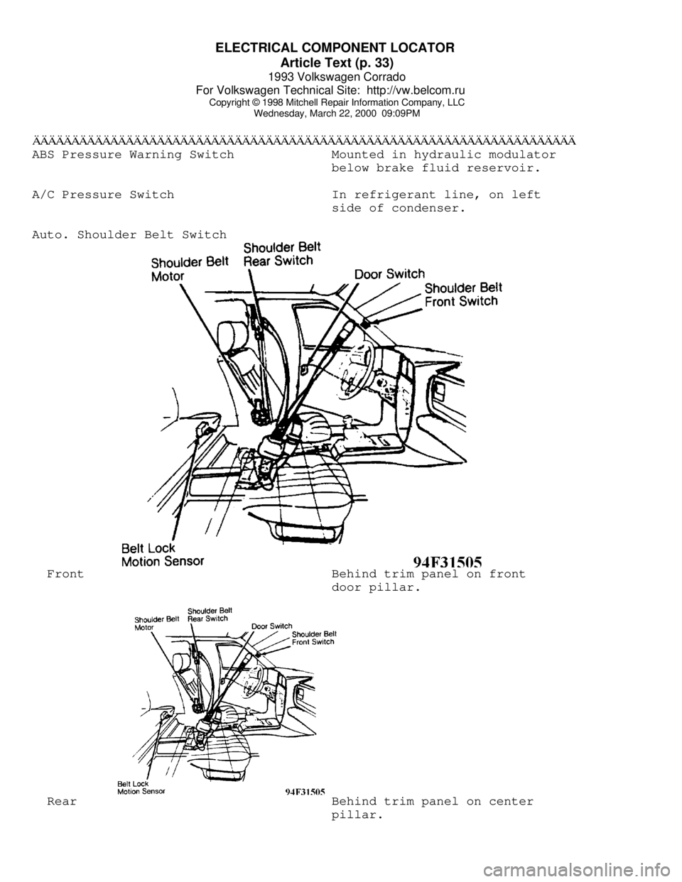
Auto. Shoulder Belt Switch Front Behind trim panel on front
door pillar. Rear Behind trim panel on center
pillar.
Page 492 of 920

ELECTRICAL COMPONENT LOCATOR
Article Text (p. 34)
1993 Volkswagen Corrado
For Volkswagen Technical Site: http://vw.belcom.ru
Copyright © 1998 Mitchell Repair Information Company, LLC
Wednesday, March 22, 2000 09:09PM
Back-Up Light Switch Mounted near gear selector
shaft on transmission.
Brake Fluid Level Switch In cap on brake fluid
reservoir.
Brake/Stoplight Switch On bracket, above brake pedal.
Cooling Fan Thermoswitch On lower left side of
radiator.
Clutch Switch On bracket, above clutch
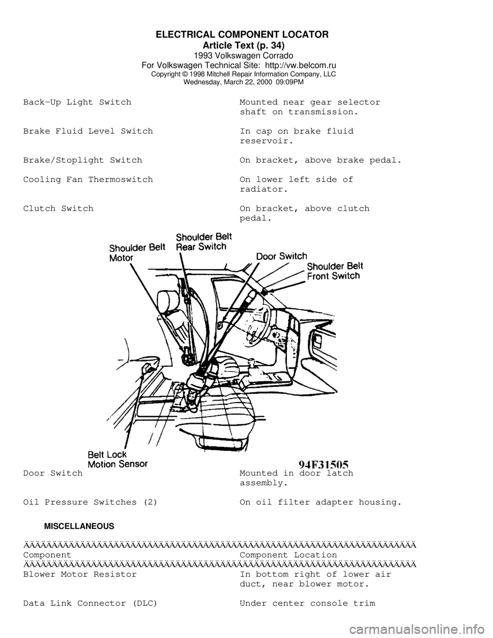
pedal.Door Switch Mounted in door latch
assembly.
Oil Pressure Switches (2) On oil filter adapter housing.
MISCELLANEOUSÄÄÄÄÄÄÄÄÄÄÄÄÄÄÄÄÄÄÄÄÄÄÄÄÄÄÄÄÄÄÄÄÄÄÄÄÄÄÄÄÄÄÄÄÄÄÄÄÄÄÄÄÄÄÄÄÄÄÄÄÄÄÄÄÄÄÄÄÄÄComponent Component Location
ÄÄÄÄÄÄÄÄÄÄÄÄÄÄÄÄÄÄÄÄÄÄÄÄÄÄÄÄÄÄÄÄÄÄÄÄÄÄÄÄÄÄÄÄÄÄÄÄÄÄÄÄÄÄÄÄÄÄÄÄÄÄÄÄÄÄÄÄÄÄBlower Motor Resistor In bottom right of lower air
duct, near blower motor.
Data Link Connector (DLC) Under center console trim
Page 493 of 920

ELECTRICAL COMPONENT LOCATOR
Article Text (p. 35)
1993 Volkswagen Corrado
For Volkswagen Technical Site: http://vw.belcom.ru
Copyright © 1998 Mitchell Repair Information Company, LLC
Wednesday, March 22, 2000 09:09PM
plate.
Instrument Cluster Voltage Stabilizer On back of instrument cluster,
above fuel gauge.ÄÄÄÄÄÄÄÄÄÄÄÄÄÄÄÄÄÄÄÄÄÄÄÄÄÄÄÄÄÄÄÄÄÄÄÄÄÄÄÄÄÄÄÄÄÄÄÄÄÄÄÄÄÄÄÄÄÄÄÄÄÄÄÄÄÄÄÄÄÄEND OF ARTICLE
Page 494 of 920

D - ADJUSTMENTS
Article Text
1993 Volkswagen Corrado
For Volkswagen Technical Site: http://vw.belcom.ru
Copyright © 1998 Mitchell Repair Information Company, LLC
Wednesday, March 22, 2000 08:59PM
ARTICLE BEGINNING
1993 ENGINE PERFORMANCE
On-Vehicle Adjustments
Corrado SLC
ENGINE MECHANICAL
Before performing any on-vehicle adjustments to fuel or
ignition systems, ensure engine mechanical condition is okay.
VALVE CLEARANCE
NOTE: All models use hydraulic lifters. No adjustments are
required.
IGNITION TIMING
NOTE: See ENTERING SELF-DIAGNOSTICS in the G - TESTS W/CODES
article in this section for additional scan tester
operating instructions.
VR6 IGNITION TIMING
1) Start and warm engine to normal operating temperature.
Ensure engine oil temperature is 176øF (80øC). Ensure A/C and
electrical loads are off, including cooling fan.
2) Connect engine analyzer to engine. Connect Scan Tester
(VAG 1551) to Data Link Connectors (DLC) located in center console, in
front of shift lever. Ensure no Diagnostic Trouble Codes (DTC) are
stored.
3) Ensure throttle position sensor is properly adjusted.
Ensure idle air control valve is okay. Valve must vibrate or hum.
Connect CO tester using Adapter (VAG 1363/3) on CO tap tube. DO NOT
remove oxygen sensor. Ensure exhaust system has no leaks.
4) Start engine and let it run at closed throttle (less than
1500 RPM). Operate scan tester and observe display. Press "1" button
to select RAPID DATA TRANSFER function. Press "Q" button to enter
input. Press right arrow button.
5) Press "0" and "1" buttons to select ENGINE ELECTRONICS
function. Press "Q" button to enter input. Press right arrow button,
then "0" and "4" buttons to select BASIC SETTING function. Press "Q"
button to enter input.
6) Press "0" and "1" buttons to select INPUT DISPLAY GROUP
NUMBER 01. Press "Q" button to enter input. Scan tester will display
SYSTEM IN BASIC ADJUSTMENT 1 through 4. Briefly increase engine speed
and then let it run for 2 minutes at closed throttle. Scan tester
displays idle speed in field one and ignition timing in field four.
Check CO level on CO tester.
7) When radiator cooling fan stops running, end basic setting
Page 495 of 920

D - ADJUSTMENTS
Article Text (p. 2)
1993 Volkswagen Corrado
For Volkswagen Technical Site: http://vw.belcom.ru
Copyright © 1998 Mitchell Repair Information Company, LLC
Wednesday, March 22, 2000 08:59PM
function by pressing right arrow button. Press "0" and "6" for END
OUTPUT function. Press "Q" button to enter input.
8) If idle speed, CO level or ignition timing is incorrect,
turn ignition off. Check accelerator pedal and throttle cable for ease
of operation. Check dashpot adjustment. Check throttle position
sensor, idle air control valve, and EGR valve.
IDLE SPEED & MIXTURE
NOTE: Mixture adjustment is NOT a part of normal tune-up procedure
and should not be performed unless mixture control unit is
replaced or vehicle fails emissions testing.
NOTE: Ensure fuel system pressure is correct before attempting
idle speed or mixture adjustment.
VR6 IDLE SPEED & MIXTURE ADJUSTMENT
See VR6 IGNITION TIMING under IGNITION TIMING near the
beginning of this article.
THROTTLE BODY
THROTTLE BODY ADJUSTMENT
CAUTION: Throttle limiting (stop) screw is set by manufacturer and
should NOT be moved. If screw is accidentally turned,
perform throttle body adjustment.
If stop screw for basic throttle adjustment has been moved,
replace throttle body.
DASHPOT
Open and close throttle until dashpot piston contacts roller.
With throttle in this position, check gap between limiter (stop) screw
and throttle. Gap between limiter (stop) screw and throttle lever must
be 0.10-0.14" (2.5-3.5 mm).
IDLE & FULL THROTTLE SWITCHES
THROTTLE POSITION (TP) SENSOR ADJUSTMENT
1) Connect Scan Tester (VAG 1551) to Data Link Connectors
(DLC) located in center console, in front of shift lever. Turn
ignition on. Operate scan tester and select RAPID DATA TRANSFER,
ENGINE ELECTRONICS, then READ MEASURING VALUE BLOCK functions.
2) Press "0" and "3" buttons to select INSERT DISPLAY GROUP
NUMBER 03 function. Press "Q" button to enter input. Slowly open
throttle, while observing display in channel 3, until throttle is wide
open. Numerical value must increase uniformly over entire opening
Page 496 of 920

D - ADJUSTMENTS
Article Text (p. 3)
1993 Volkswagen Corrado
For Volkswagen Technical Site: http://vw.belcom.ru
Copyright © 1998 Mitchell Repair Information Company, LLC
Wednesday, March 22, 2000 08:59PM
range and without interruption.
3) Reading should be 5-19 at idle. Reading should be 94-100
at full throttle stop. If readings are correct, press right arrow
button. Press "0" and "6" to select ENDING OUTPUT function. Press "Q"
button to enter input. If readings are incorrect, check TP sensor
circuit or replace TP sensor as necessary.
END OF ARTICLE
Page 497 of 920

DEFOGGER - REAR WINDOW
Article Text
1993 Volkswagen Corrado
For Volkswagen Technical Site: http://vw.belcom.ru
Copyright © 1998 Mitchell Repair Information Company, LLC
Wednesday, March 22, 2000 09:08PM
ARTICLE BEGINNING
1993 ACCESSORIES & EQUIPMENT
Volkswagen Rear Window Defoggers
Volkswagen; Cabriolet, Corrado SLC, EuroVan,
Fox, Golf, GTI, Jetta, Passat
DESCRIPTION & OPERATION
Ignition must be on for rear window defogger to operate.
Power to control switch is applied through fuse in fuse block. An
indicator light in the control switch comes on when the defogger is
turned on. Control switch also provides power to heating element in
both outside mirrors.
TROUBLE SHOOTING
DEFOGGER DOES NOT WORK
Check for blown fuse, defective defogger switch, open wiring
or poor connections. Check for breaks in rear window defogger grid.
See FILAMENT TEST under TESTING.
INDICATOR LIGHT DOES NOT WORK
Check for burned bulb, blown fuse, open wiring or poor
connection.
TESTING
SYSTEM TEST
Ensure and control switch are okay. Turn ignition and control
switch on. After a few minutes, feel glass for warmth. If glass is not
warm, use a test light to check for battery voltage at grid feed wire.
If no voltage is present, check control switch.
FILAMENT TEST
1) To locate breaks in grid filaments, connect test light
negative lead to ground side of grid. Touch opposite (positive) side
of grid with test light probe. If test light glows, grid line is okay.
Test light will glow dimmer as probe is moved toward ground side of
grid.
2) If test light does not glow, grid line is broken. To
locate break, move probe along grid line toward ground side of heat
grid until test light glows, indicating area of damage.
WIRING DIAGRAMS
Page 498 of 920

DEFOGGER - REAR WINDOW
Article Text (p. 2)
1993 Volkswagen Corrado
For Volkswagen Technical Site: http://vw.belcom.ru
Copyright © 1998 Mitchell Repair Information Company, LLC
Wednesday, March 22, 2000 09:08PM
See appropriate chassis wiring diagram in WIRING DIAGRAMS.
END OF ARTICLE
Page 499 of 920

DOOR LOCKS - POWER
Article Text
1993 Volkswagen Corrado
For Volkswagen Technical Site: http://vw.belcom.ru
Copyright © 1998 Mitchell Repair Information Company, LLC
Wednesday, March 22, 2000 09:08PM
ARTICLE BEGINNING
1993 ACCESSORIES & EQUIPMENT
Volkswagen Power Door Locks
Volkswagen; Corrado SLC, Passat
DESCRIPTION & OPERATION
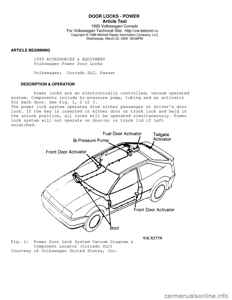
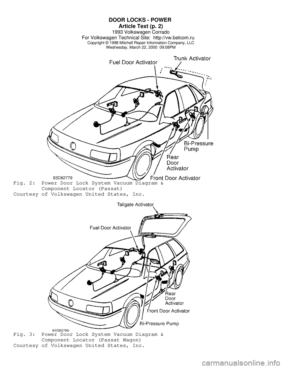
Power locks are an electronically controlled, vacuum operated
system. Components include bi-pressure pump, tubing and an activator
for each door. See Fig. 1, 2 or 3.
The power lock system operates from either passenger or driver's door
lock. If the key is inserted in either door or trunk lock and held in
the unlock position, all locks will be operated simultaneously. Power
lock system will not operate on door(s) or trunk lid if left
unlatched.Fig. 1: Power Door Lock System Vacuum Diagram &
Component Locator (Corrado SLC)
Courtesy of Volkswagen United States, Inc.
Page 500 of 920

DOOR LOCKS - POWER
Article Text (p. 2)
1993 Volkswagen Corrado
For Volkswagen Technical Site: http://vw.belcom.ru
Copyright © 1998 Mitchell Repair Information Company, LLC
Wednesday, March 22, 2000 09:08PMFig. 2: Power Door Lock System Vacuum Diagram &
Component Locator (Passat)
Courtesy of Volkswagen United States, Inc.Fig. 3: Power Door Lock System Vacuum Diagram &
Component Locator (Passat Wagon)
Courtesy of Volkswagen United States, Inc.