check engine light VOLKSWAGEN JETTA 1998 Owner's Manual
[x] Cancel search | Manufacturer: VOLKSWAGEN, Model Year: 1998, Model line: JETTA, Model: VOLKSWAGEN JETTA 1998Pages: 339, PDF Size: 2.35 MB
Page 133 of 339
Downloaded from www.Manualslib.com manuals search engine 01-130
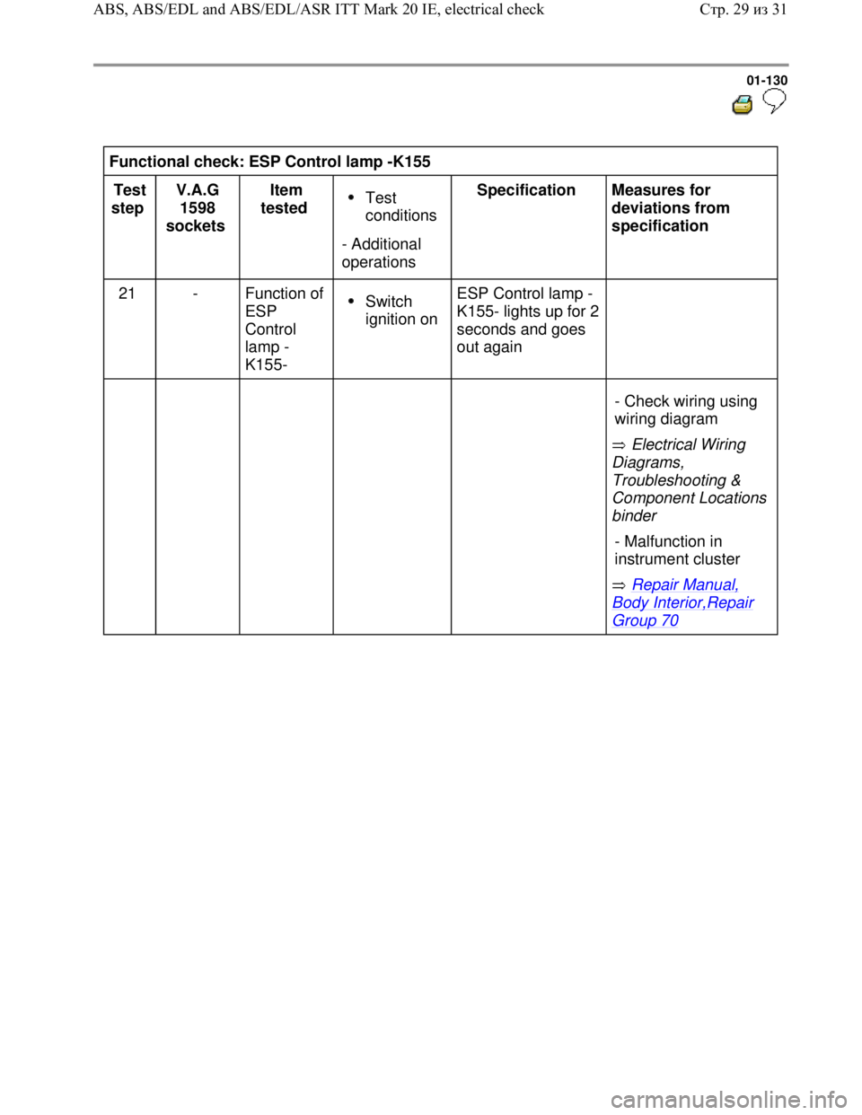
Functional check: ESP Control lamp -K155
Test
step V.A.G
1598
sockets Item
tested
Test
conditions
- Additional
operations Specification
Measures for
deviations from
specification
21 - Function of
ESP
Control
lamp -
K155-
Switch
ignition on ESP Control lamp -
K155- lights up for 2
seconds and goes
out again
Electrical Wiring
Diagrams,
Troubleshooting &
Component Locations
binder
Repair Manual,
Body Interior,Repair
Group 70 - Check wiring using
wiring diagram
- Malfunction in
instrument cluster
Стр. 29из 31 ABS, ABS/EDL and ABS/EDL/ASR ITT Mark 20 IE, electrical check
Page 134 of 339
Downloaded from www.Manualslib.com manuals search engine 01-131
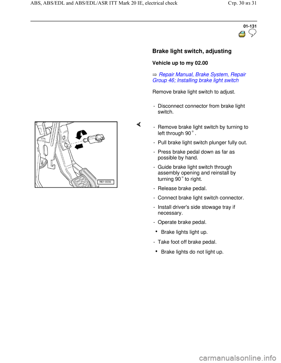
Brake light switch, adjusting
Vehicle up to my 02.00
Repair Manual, Brake System, Repair
Group 46; Installing brake light switch
Remove brake light switch to adjust.
- Disconnect connector from brake light
switch.
- Remove brake light switch by turning to
left through 90 .
- Pull brake light switch plunger fully out.
- Press brake pedal down as far as
possible by hand.
- Guide brake light switch through
assembly opening and reinstall by
turning 90 to right.
- Release brake pedal.
- Connect brake light switch connector.
- Install driver's side stowage tray if
necessary.
- Operate brake pedal.
Brake lights light up.
- Take foot off brake pedal.
Brake lights do not light up.
Стр. 30из 31 ABS, ABS/EDL and ABS/EDL/ASR ITT Mark 20 IE, electrical check
Page 135 of 339
Downloaded from www.Manualslib.com manuals search engine 01-132
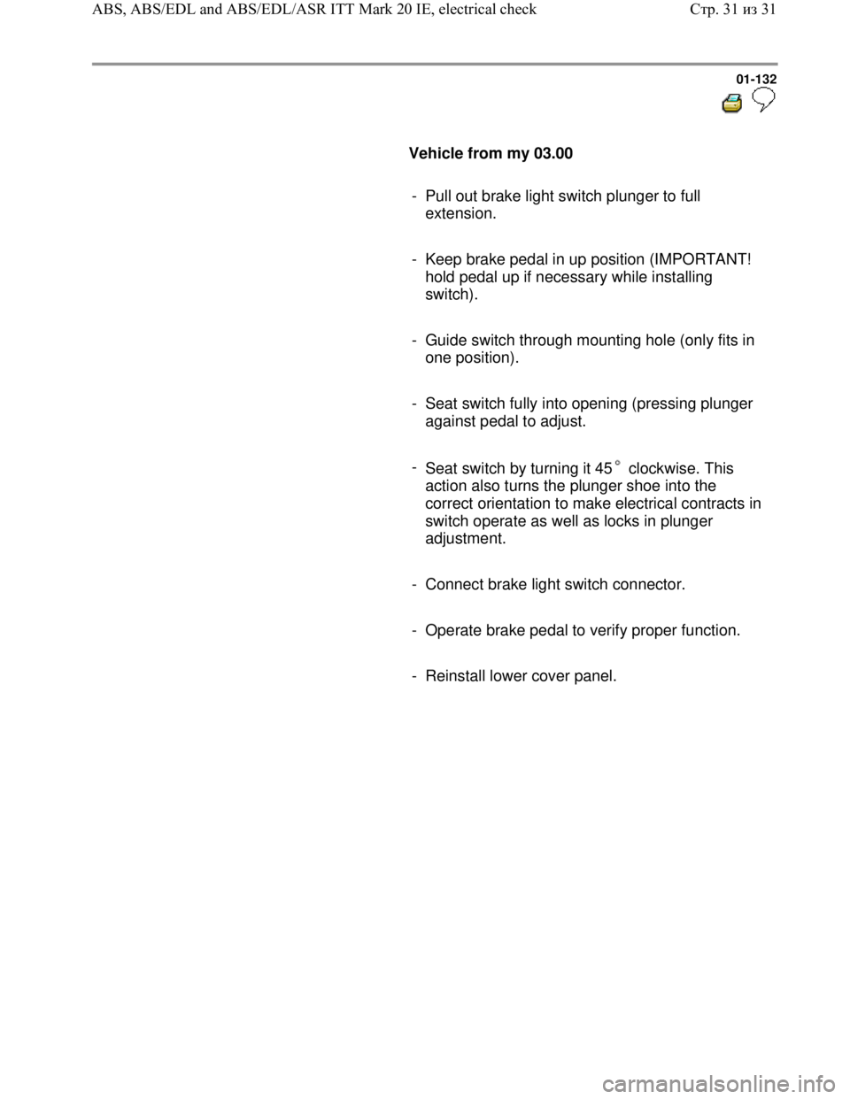
Vehicle from my 03.00
- Pull out brake light switch plunger to full
extension.
- Keep brake pedal in up position (IMPORTANT!
hold pedal up if necessary while installing
switch).
- Guide switch through mounting hole (only fits in
one position).
- Seat switch fully into opening (pressing plunger
against pedal to adjust.
-
Seat switch by turning it 45 clockwise. This
action also turns the plunger shoe into the
correct orientation to make electrical contracts in
switch operate as well as locks in plunger
adjustment.
- Connect brake light switch connector.
- Operate brake pedal to verify proper function.
- Reinstall lower cover panel.
Стр. 31из 31 ABS, ABS/EDL and ABS/EDL/ASR ITT Mark 20 IE, electrical check
Page 138 of 339
Downloaded from www.Manualslib.com manuals search engine 01-135
Sporadic (irregular) malfunctions will also be
recognized and stored. But if malfunctions
affecting the data bus system do not occur again
within the next 15 vehicle start and driving off
sequences, or other malfunctions within the next
50 vehicle start and driving off sequences, they
will be erased from DTC memory except for the
malfunction "Control module faulty" (forget-
malfunction counter).
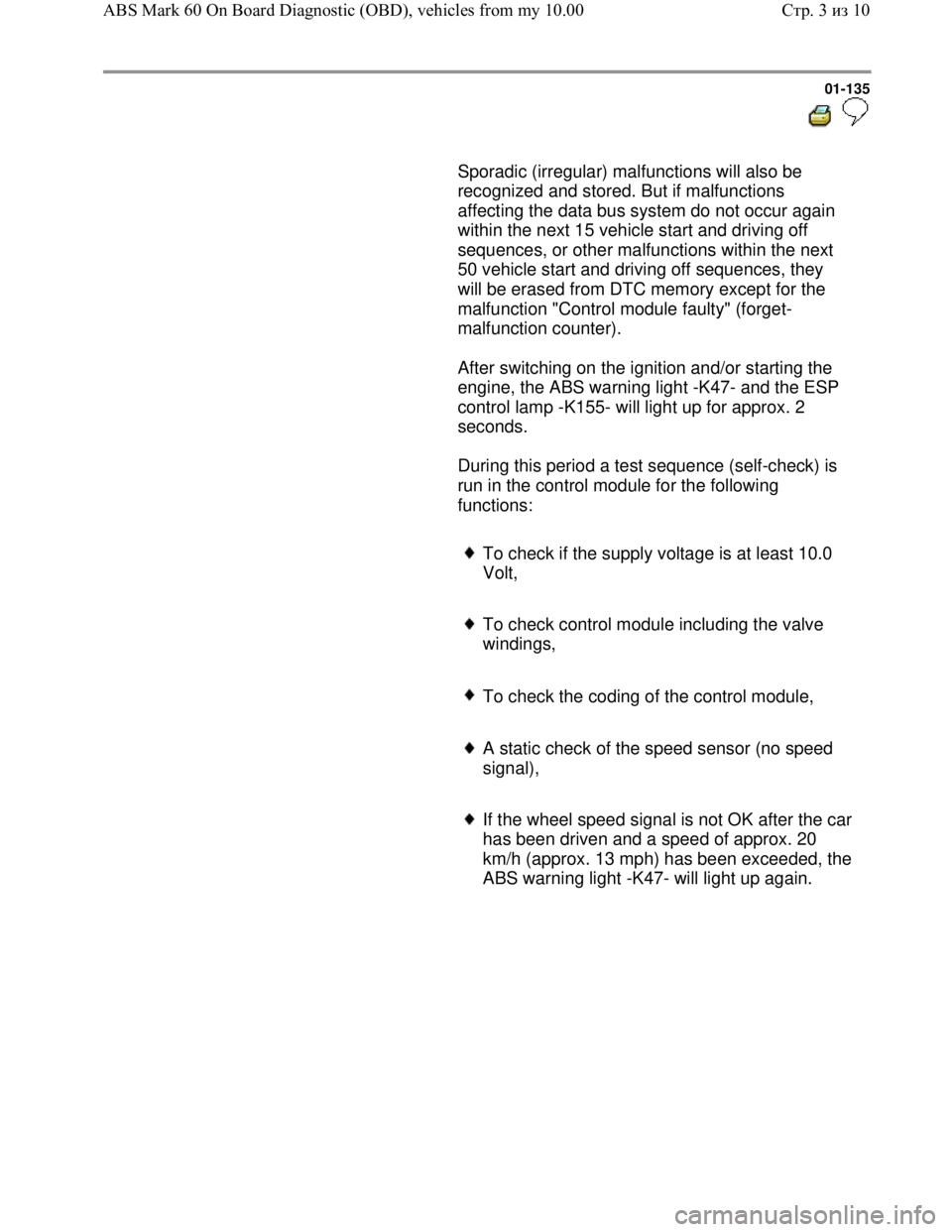
After switching on the ignition and/or starting the
engine, the ABS warning light -K47- and the ESP
control lamp -K155- will light up for approx. 2
seconds.
During this period a test sequence (self-check) is
run in the control module for the following
functions:
To check if the supply voltage is at least 10.0
Volt,
To check control module including the valve
windings,
To check the coding of the control module,
A static check of the speed sensor (no speed
signal),
If the wheel speed signal is not OK after the car
has been driven and a speed of approx. 20
km/h (approx. 13 mph) has been exceeded, the
ABS warning light -K47- will light up again.
Стр. 3из 10 ABS Mark 60 On Board Diagnostic (OBD), vehicles from my 10.00
Page 142 of 339
Downloaded from www.Manualslib.com manuals search engine 01-139
Safety precautions and fundamental
points regarding troubleshooting
Note:
The ABS is a vehicle safety system; the
appropriate knowledge is necessary to work on
the system.
In order to check complaints and to be able to
carry out pin-pointed troubleshooting, the
Diagnostic Trouble Code (DTC) memory must
be checked before commencing work on the
ABS system.
Only separate connectors when the ignition is
switched off.
Observe the appropriate instructions regarding
the handling of brake fluid.
Repair Manual, Brake System, Repair Group
47
ABS malfunctions are indicated by the ABS
warning light illuminating. Certain malfunctions
will only be recognized at speeds above 20
km/h (approx. 13 mph) (carry out road test).
If the ABS -K47- and the brake system -K118-
warning lights do not illuminate, but the brake
system is not functioning correctly then the
malfunction must be sought in the conventional
braking system.
Repair Manual, Brake System, Repair Group
45
Стр. 7из 10 ABS Mark 60 On Board Diagnostic (OBD), vehicles from my 10.00
Page 156 of 339
Downloaded from www.Manualslib.com manuals search engine 01-151
Repair Manual,
Brake System,
Repair Group 47;
Brake system
vacuum pump -V192
Repair Manual,
Brake System,
Repair Group 47;
Brake system
vacuum pump -V192
Repair Manual,
Brake System,
Repair Group 46;
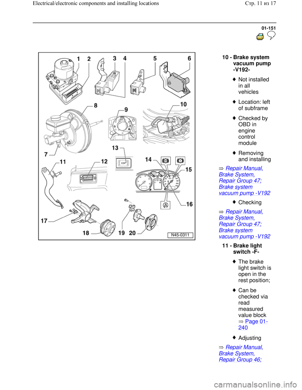
10 -
Brake system
vacuum pump
-V192-
Not installed
in all
vehicles
Location: left
of subframe
Checked by
OBD in
engine
control
module
Removing
and installing
Checking
11 -
Brake light
switch -F-
The brake
light switch is
open in the
rest position;
Can be
checked via
read
measured
value block
Page 01
-
240
Adjusting
Стр. 11из 17 Electrical/electronic components and installing locations
Page 167 of 339
Downloaded from www.Manualslib.com manuals search engine 01-159
On Board Diagnostic (OBD),
performing
Test prerequisites for OBD
The tires installed to all wheels must be of
the same (approved) size; tires inflated to
prescribed pressure.
Mechanical/hydraulic parts of the brake
system including brake light switch and
brake lights OK.
Hydraulic lines and connections not leaking
(visual check of hydraulic unit, brake
calipers, wheel cylinders, tandem master
brake cylinder).
ABS Control Module (w/EDL) -J104- is
correctly bolted to ABS Hydraulic Unit -
N55-.
Connector on ABS Control Module (w/EDL)
-J104- correctly plugged-in (retainer is
engaged).
Check contacts of ABS components for
damage and correct seating.
All fuses according to wiring diagram OK
(remove fuse from fuse holder to check).
Supply voltage OK (at least 10.0 V).
Стр. 1из 129 On Board Diagnostic (OBD), performing
Page 172 of 339
Downloaded from www.Manualslib.com manuals search engine 01-164
Note:
The ABS function is switched off in the control
module during the OBD. This is indicated by th
e
flashing of ABS warning light -K47- and warning
light for brake system -K118-. If there is a
malfunction currently, it will be indicated by the
lights being on constantly.
The DTC memory can be erased after
successful check and repair.
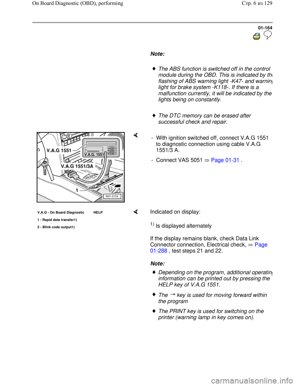
- With ignition switched off, connect V.A.G 1551
to diagnostic connection using cable V.A.G
1551/3 A.
- Connect VAS 5051 Page 01
-31 .
V.A.G - On Board Diagnostic HELP
1 - Ra
pid data transfer1)
2 - Blink code output1)
Indicated on display:
1) Is displayed alternately
If the display remains blank, check Data Link
Connector connection, Electrical check, Page
01-288 , test steps 21 and 22.
Note:
Depending on the program, additional operating
information can be printed out by pressing the
HELP key of V.A.G 1551.
The key is used for moving forward within
the program
The PRINT key is used for switching on the
printer (warning lamp in key comes on).
Стр. 6из 129 On Board Diagnostic (OBD), performing
Page 177 of 339
Downloaded from www.Manualslib.com manuals search engine 01-169
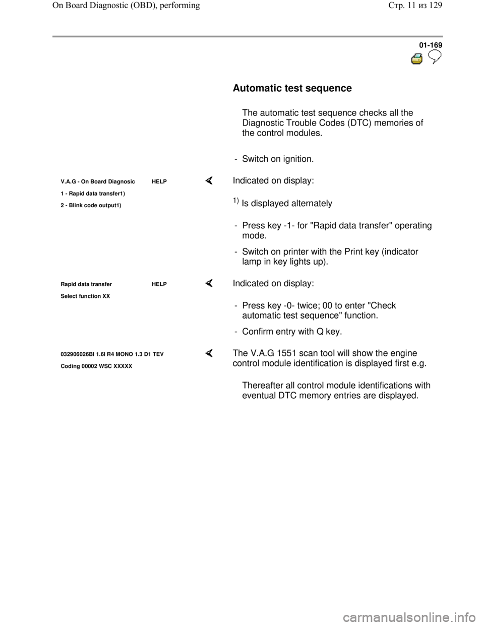
Automatic test sequence
The automatic test sequence checks all the
Diagnostic Trouble Codes (DTC) memories of
the control modules.
- Switch on ignition.
V.A.G - On Board Diagnosic HELP
1 - Rapid data transfer1
)
2 - Blink code output1)
Indicated on display:
1) Is displayed alternately
- Press key -1- for "Rapid data transfer" operating
mode.
- Switch on printer with the Print key (indicator
lamp in key lights up).
Rapid data transfer HELP
Select function XX Indicated on display:
- Press key -0- twice; 00 to enter "Check
automatic test sequence" function.
- Confirm entry with Q key.
032906026BI 1.6l R4 MONO 1.3 D1 TEV
Codin
g 00002 WSC XXXXX
The V.A.G 1551 scan tool will show the engine
control module identification is displayed first e.g.
Thereafter all control module identifications with
eventual DTC memory entries are displayed.
Стр. 11из 129 On Board Diagnostic (OBD), performing
Page 196 of 339
Downloaded from www.Manualslib.com manuals search engine 01-188
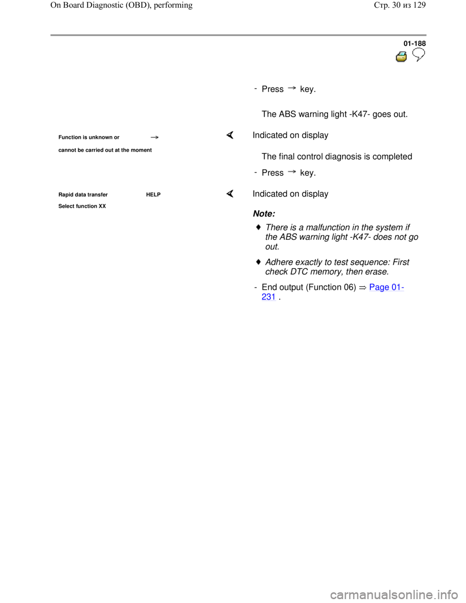
-
Press key.
The ABS warning light -K47- goes out.
Function is unknown or
cannot be carried out at the moment
Indicated on display
The final control diagnosis is completed
-
Press key.
Rapid data transfer HELP
Select function XX Indicated on display
Note:
There is a malfunction in the system if
the ABS warning light -K47- does not go
out.
Adhere exactly to test sequence: First
check DTC memory, then erase.
- End output (Function 06) Page 01
-
231 .
Стр. 30из 129 On Board Diagnostic (OBD), performing