check engine light VOLKSWAGEN JETTA 1998 Workshop Manual
[x] Cancel search | Manufacturer: VOLKSWAGEN, Model Year: 1998, Model line: JETTA, Model: VOLKSWAGEN JETTA 1998Pages: 339, PDF Size: 2.35 MB
Page 307 of 339
Downloaded from www.Manualslib.com manuals search engine 01-299
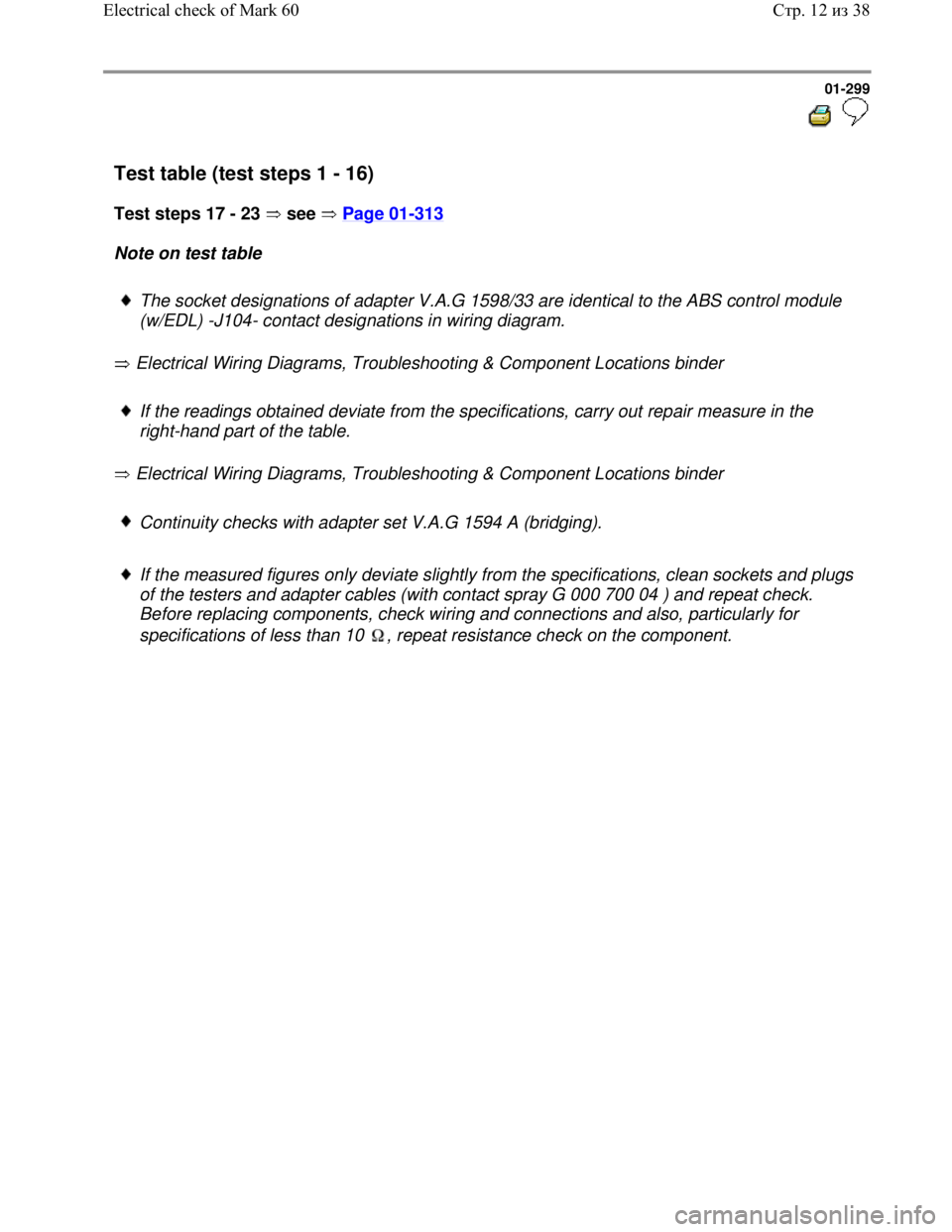
Test table (test steps 1 - 16)
Test steps 17 - 23 see Page 01
-313
Note on test table
The socket designations of adapter V.A.G 1598/33 are identical to the ABS control module
(w/EDL) -J104- contact designations in wiring diagram.
Electrical Wiring Diagrams, Troubleshooting & Component Locations binder
If the readings obtained deviate from the specifications, carry out repair measure in the
right-hand part of the table.
Electrical Wiring Diagrams, Troubleshooting & Component Locations binder
Continuity checks with adapter set V.A.G 1594 A (bridging).
If the measured figures only deviate slightly from the specifications, clean sockets and plugs
of the testers and adapter cables (with contact spray G 000 700 04 ) and repeat check.
Before replacing components, check wiring and connections and also, particularly for
specifications of less than 10 , repeat resistance check on the component.
Стр. 12из 38 Electrical check of Mark 60
Page 309 of 339
Downloaded from www.Manualslib.com manuals search engine 01-301
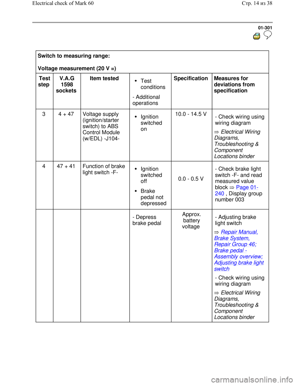
Switch to measuring range:
Voltage measurement (20 V =)
Test
step V.A.G
1598
sockets Item tested
Test
conditions
- Additional
operations Specification
Measures for
deviations from
specification
3 4 + 47 Voltage supply
(ignition/starter
switch) to ABS
Control Module
(w/EDL) -J104-
Ignition
switched
on 10.0 - 14.5 V
Electrical Wiring
Diagrams,
Troubleshooting &
Component
Locations binder - Check wiring using
wiring diagram
4 47 + 41 Function of brake
light switch -F- Ignition
switched
off
Brake
pedal not
depressed
0.0 - 0.5 V - Check brake light
switch -F- and read
measured value
block Page 01-
240 , Display group
number 003
- Depress
brake pedal Approx.
battery
voltage
Repair Manual,
Brake System,
Repair Group 46;
Brake pedal -
Assembly overview;
Adjusting brake light
switch
Electrical Wiring
Diagrams,
Troubleshooting &
Component
Locations binder - Adjusting brake
light switch
- Check wiring using
wiring diagram
Стр. 14из 38 Electrical check of Mark 60
Page 316 of 339
Downloaded from www.Manualslib.com manuals search engine 01-308
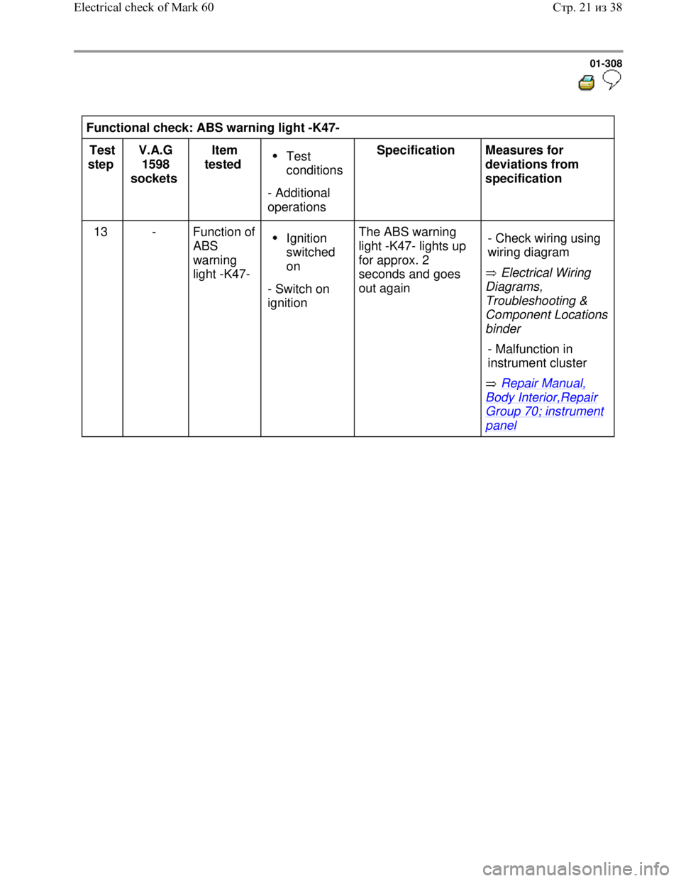
Functional check: ABS warning light -K47-
Test
step V.A.G
1598
sockets Item
tested
Test
conditions
- Additional
operations Specification
Measures for
deviations from
specification
13 - Function of
ABS
warning
light -K47-
Ignition
switched
on
- Switch on
ignition The ABS warning
light -K47- lights up
for approx. 2
seconds and goes
out again Electrical Wiring
Diagrams,
Troubleshooting &
Component Locations
binder
Repair Manual,
Body Interior,Repair
Group 70; instrument
panel - Check wiring using
wiring diagram
- Malfunction in
instrument cluster
Стр. 21из 38 Electrical check of Mark 60
Page 317 of 339
Downloaded from www.Manualslib.com manuals search engine 01-309
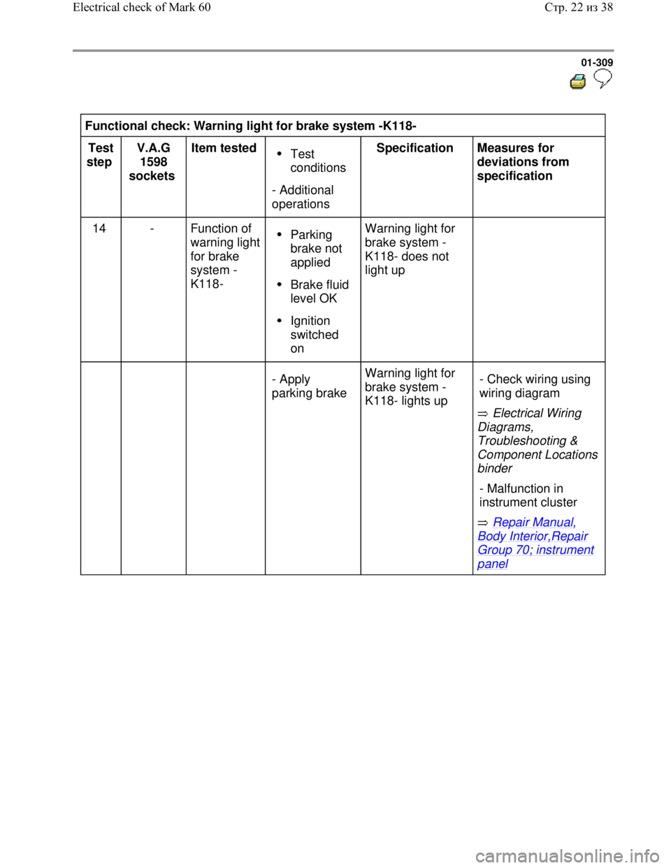
Functional check: Warning light for brake system -K118-
Test
step V.A.G
1598
sockets Item tested
Test
conditions
- Additional
operations Specification
Measures for
deviations from
specification
14 - Function of
warning light
for brake
system -
K118-
Parking
brake not
applied
Brake fluid
level OK
Ignition
switched
on Warning light for
brake system -
K118- does not
light up
- Apply
parking brake Warning light for
brake system -
K118- lights up
Electrical Wiring
Diagrams,
Troubleshooting &
Component Locations
binder
Repair Manual,
Body Interior,Repair
Group 70; instrument
panel - Check wiring using
wiring diagram
- Malfunction in
instrument cluster
Стр. 22из 38 Electrical check of Mark 60
Page 318 of 339
Downloaded from www.Manualslib.com manuals search engine 01-310
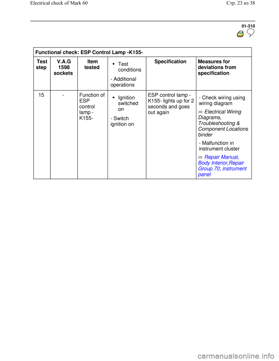
Functional check: ESP Control Lamp -K155-
Test
step V.A.G
1598
sockets Item
tested
Test
conditions
- Additional
operations Specification
Measures for
deviations from
specification
15 - Function of
ESP
control
lamp -
K155-
Ignition
switched
on
- Switch
ignition on ESP control lamp -
K155- lights up for 2
seconds and goes
out again Electrical Wiring
Diagrams,
Troubleshooting &
Component Locations
binder
Repair Manual,
Body Interior,Repair
Group 70; instrument
panel - Check wiring using
wiring diagram
- Malfunction in
instrument cluster
Стр. 23из 38 Electrical check of Mark 60
Page 319 of 339
Downloaded from www.Manualslib.com manuals search engine 01-311
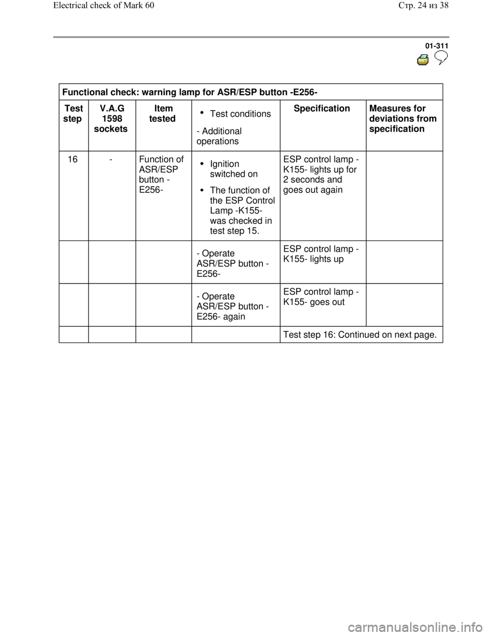
Functional check: warning lamp for ASR/ESP button -E256-
Test
step V.A.G
1598
sockets Item
tested
Test conditions
- Additional
operations Specification
Measures for
deviations from
specification
16 - Function of
ASR/ESP
button -
E256-
Ignition
switched on
The function of
the ESP Control
Lamp -K155-
was checked in
test step 15. ESP control lamp -
K155- lights up for
2 seconds and
goes out again
- Operate
ASR/ESP button -
E256- ESP control lamp -
K155- lights up
- Operate
ASR/ESP button -
E256- again ESP control lamp -
K155- goes out
Test step 16: Continued on next page.
Стр. 24из 38 Electrical check of Mark 60