check engine light VOLKSWAGEN JETTA 1998 Workshop Manual
[x] Cancel search | Manufacturer: VOLKSWAGEN, Model Year: 1998, Model line: JETTA, Model: VOLKSWAGEN JETTA 1998Pages: 339, PDF Size: 2.35 MB
Page 285 of 339
Downloaded from www.Manualslib.com manuals search engine 01-277
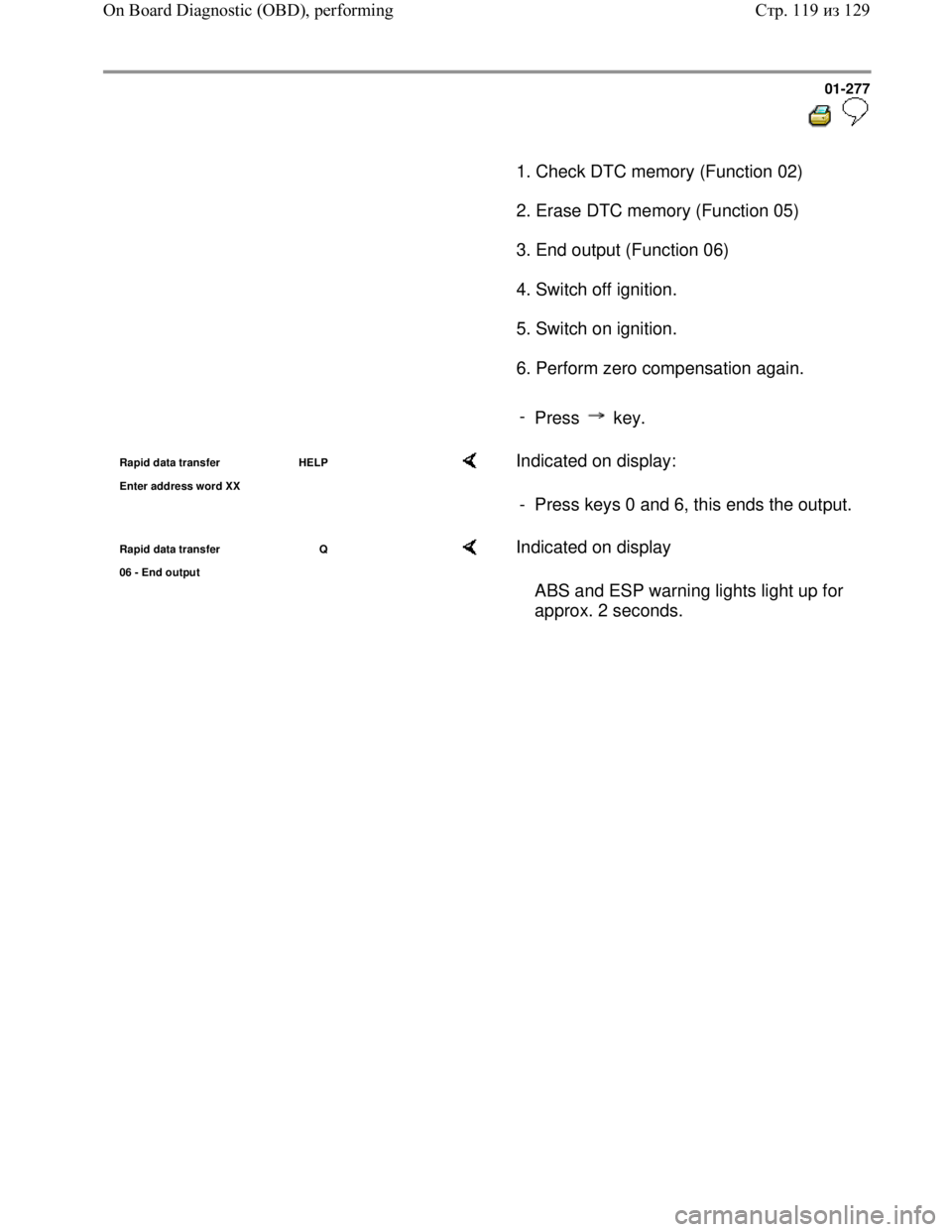
1. Check DTC memory (Function 02)
2. Erase DTC memory (Function 05)
3. End output (Function 06)
4. Switch off ignition.
5. Switch on ignition.
6. Perform zero compensation again.
-
Press key.
Rapid data transfer HELP
Enter address word XX Indicated on display:
- Press keys 0 and 6, this ends the output.
Rapid data transfer Q
06 - End output Indicated on display
ABS and ESP warning lights light up for
approx. 2 seconds.
Стр. 119из 129 On Board Diagnostic (OBD), performing
Page 287 of 339
Downloaded from www.Manualslib.com manuals search engine 01-279
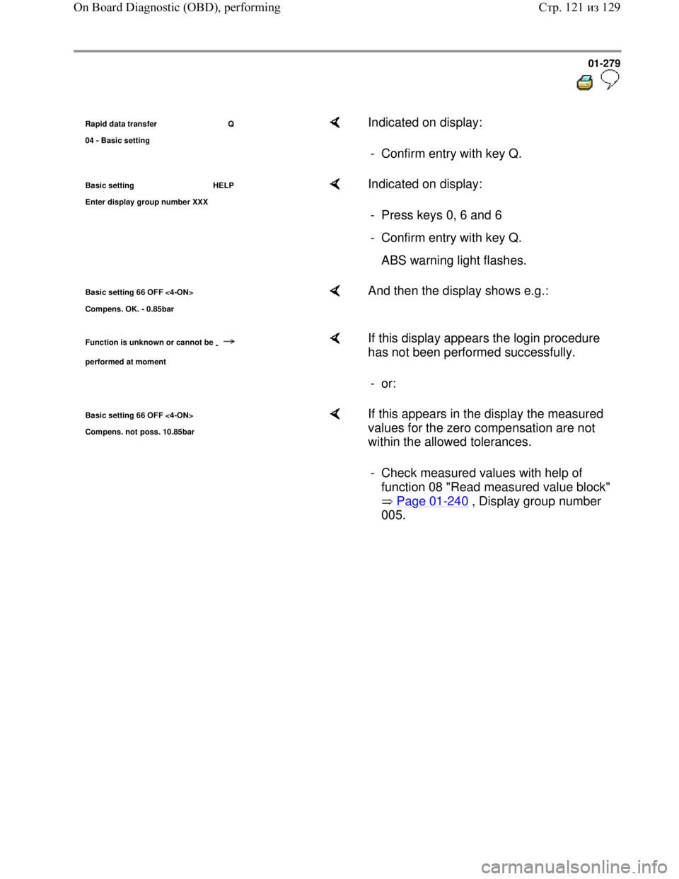
Rapid data transfer Q
04 - Basic settin
g
Indicated on display:
- Confirm entry with key Q.
Basic setting HELP
Enter dis
play group number XXX
Indicated on display:
- Press keys 0, 6 and 6
- Confirm entry with key Q.
ABS warning light flashes.
Basic setting 66 OFF <4-ON>
Compens. OK. - 0.85bar And then the display shows e.g.:
Function is unknown or cannot be
-
performed at moment
If this display appears the login procedure
has not been performed successfully.
- or:
Basic setting 66 OFF <4-ON>
Com
pens. not poss. 10.85bar
If this appears in the display the measured
values for the zero compensation are not
within the allowed tolerances.
- Check measured values with help of
function 08 "Read measured value block"
Page 01
-240 , Display group number
005.
Стр. 121из 129 On Board Diagnostic (OBD), performing
Page 288 of 339
Downloaded from www.Manualslib.com manuals search engine 01-280
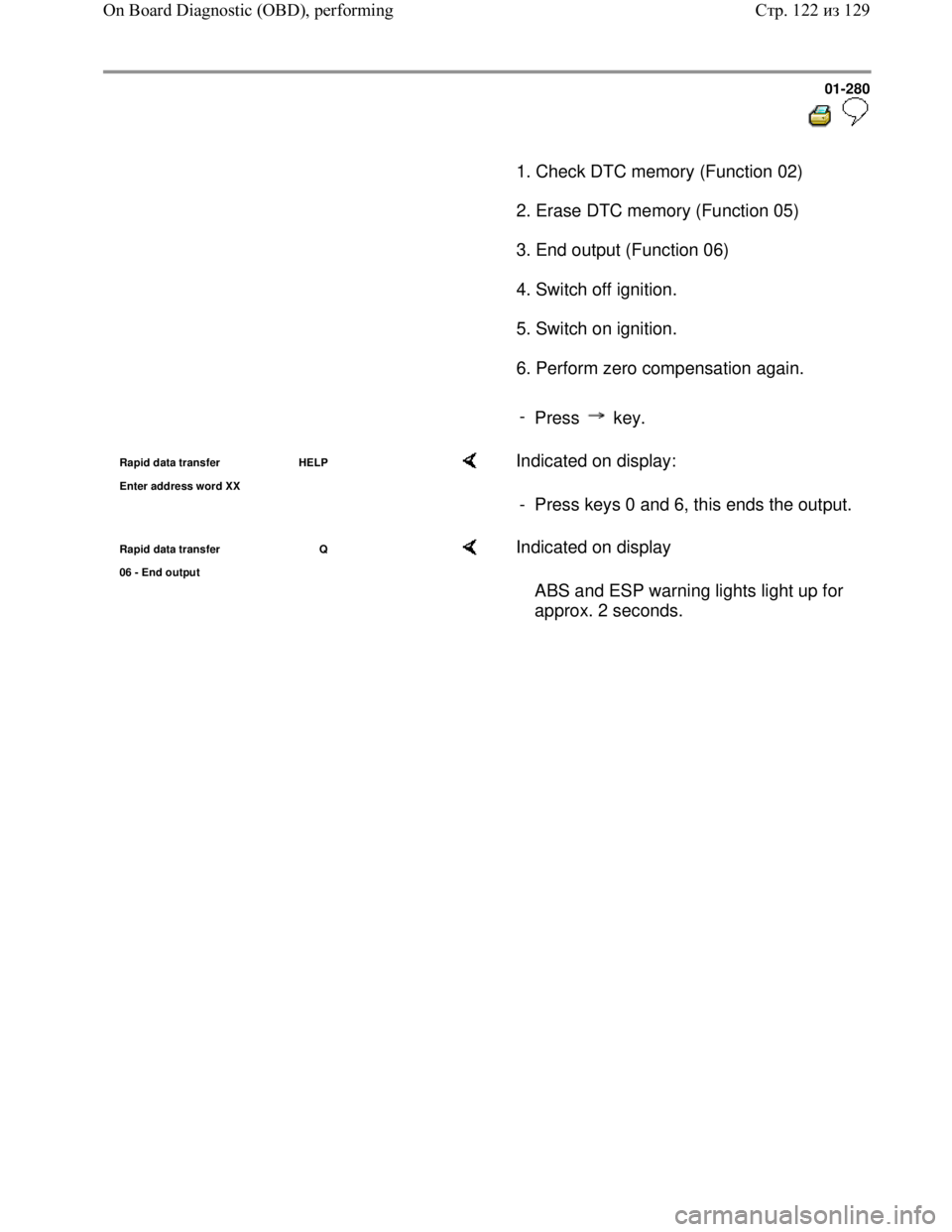
1. Check DTC memory (Function 02)
2. Erase DTC memory (Function 05)
3. End output (Function 06)
4. Switch off ignition.
5. Switch on ignition.
6. Perform zero compensation again.
-
Press key.
Rapid data transfer HELP
Enter address word XX Indicated on display:
- Press keys 0 and 6, this ends the output.
Rapid data transfer Q
06 - End output Indicated on display
ABS and ESP warning lights light up for
approx. 2 seconds.
Стр. 122из 129 On Board Diagnostic (OBD), performing
Page 290 of 339
Downloaded from www.Manualslib.com manuals search engine 01-282
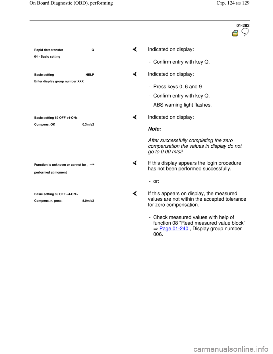
Rapid data transfer Q
04 - Basic settin
g
Indicated on display:
- Confirm entry with key Q.
Basic setting HELP
Enter dis
play group number XXX
Indicated on display:
- Press keys 0, 6 and 9
- Confirm entry with key Q.
ABS warning light flashes.
Basic setting 69 OFF <4-ON>
Compens. OK 0.3m/s2 Indicated on display:
Note:
After successfully completing the zero
compensation the values in display do not
go to 0.00 m/s2
Function is unknown or cannot be
-
performed at moment
If this display appears the login procedure
has not been performed successfully.
- or:
Basic setting 69 OFF <4-ON>
Compens. n. poss. 5.0m/s2 If this appears on display, the measured
values are not within the accepted tolerance
for zero compensation.
- Check measured values with help of
function 08 "Read measured value block"
Page 01
-240 , Display group number
006.
Стр. 124из 129 On Board Diagnostic (OBD), performing
Page 291 of 339
Downloaded from www.Manualslib.com manuals search engine 01-283
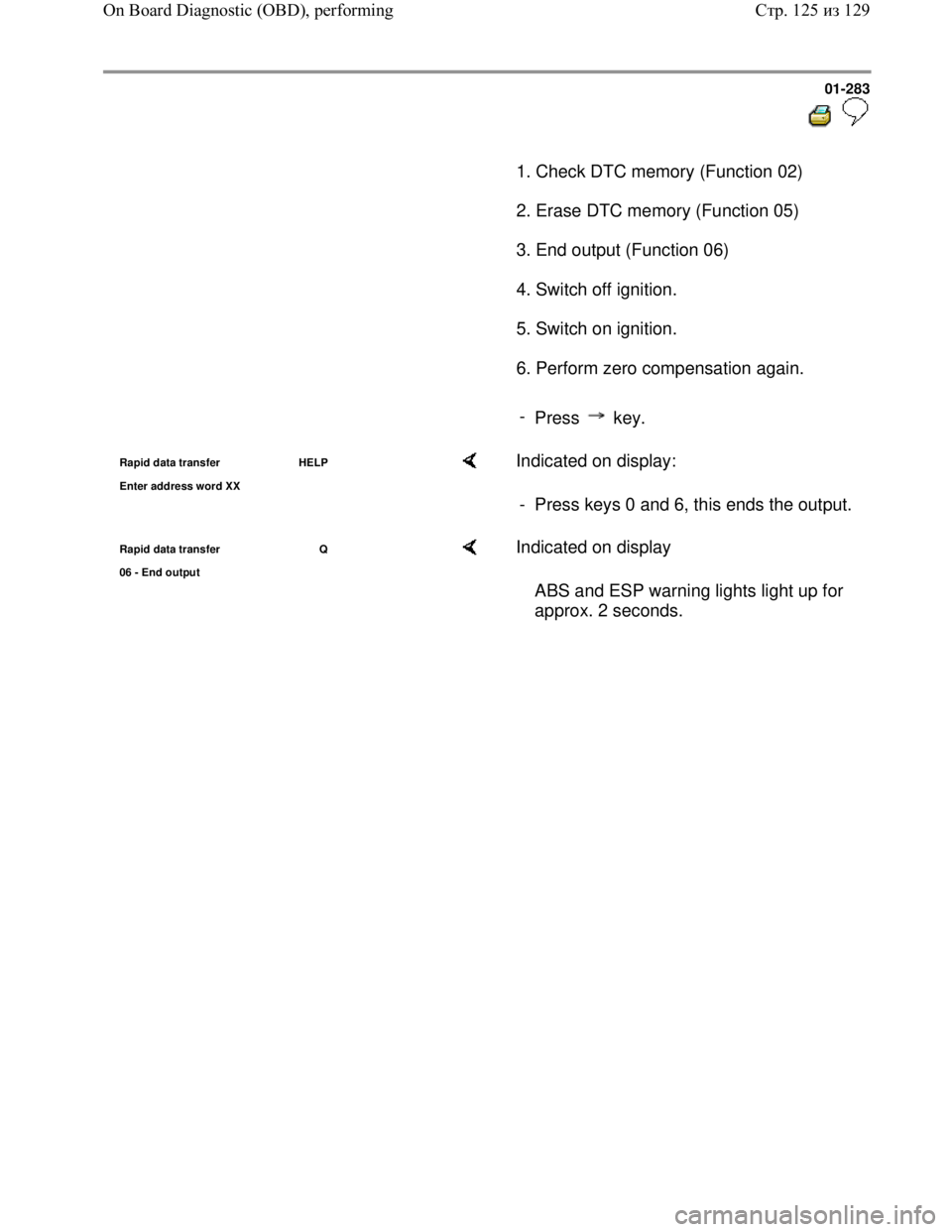
1. Check DTC memory (Function 02)
2. Erase DTC memory (Function 05)
3. End output (Function 06)
4. Switch off ignition.
5. Switch on ignition.
6. Perform zero compensation again.
-
Press key.
Rapid data transfer HELP
Enter address word XX Indicated on display:
- Press keys 0 and 6, this ends the output.
Rapid data transfer Q
06 - End output Indicated on display
ABS and ESP warning lights light up for
approx. 2 seconds.
Стр. 125из 129 On Board Diagnostic (OBD), performing
Page 294 of 339
Downloaded from www.Manualslib.com manuals search engine 01-286
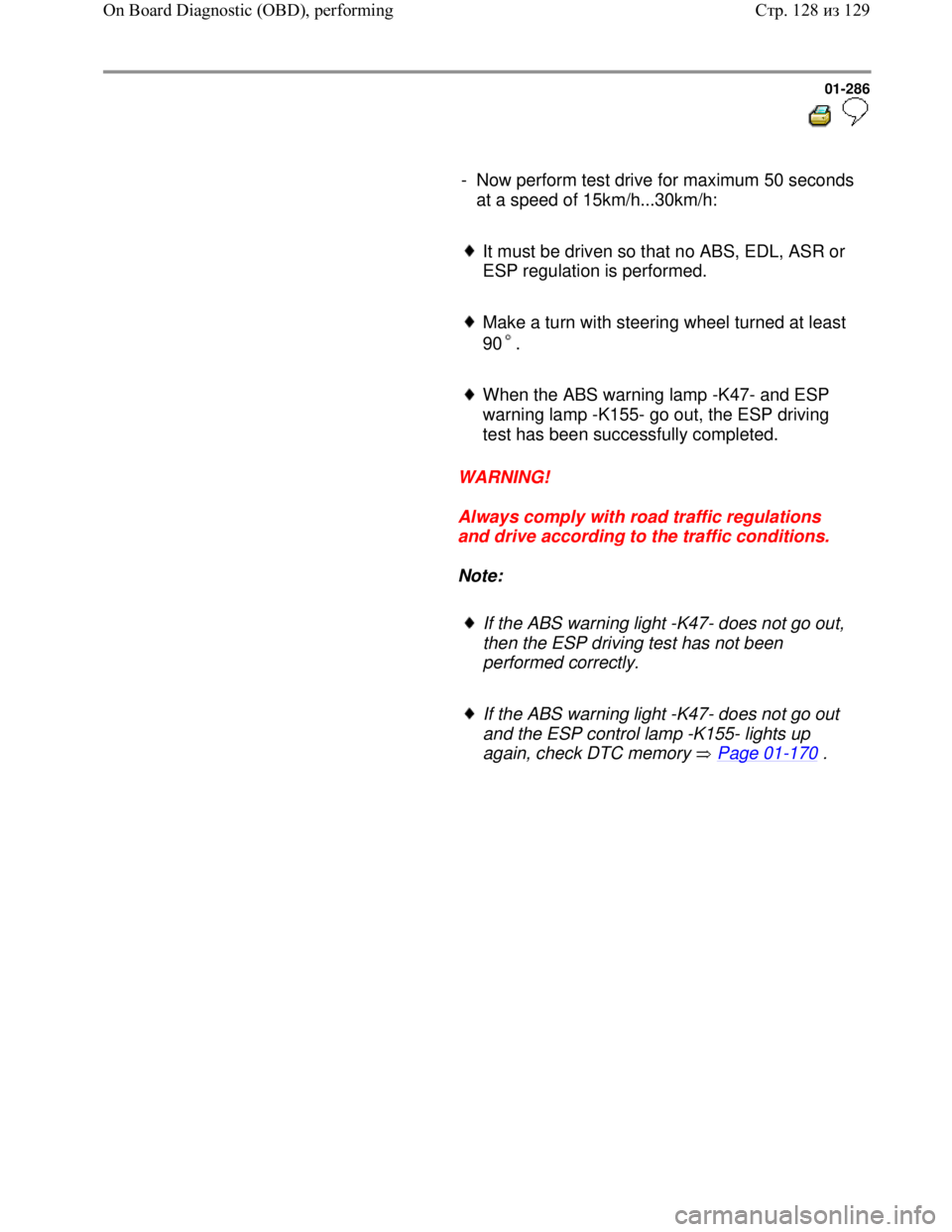
- Now perform test drive for maximum 50 seconds
at a speed of 15km/h...30km/h:
It must be driven so that no ABS, EDL, ASR or
ESP regulation is performed.
Make a turn with steering wheel turned at least
90 .
When the ABS warning lamp -K47- and ESP
warning lamp -K155- go out, the ESP driving
test has been successfully completed.
WARNING!
Always comply with road traffic regulations
and drive according to the traffic conditions.
Note:
If the ABS warning light -K47- does not go out,
then the ESP driving test has not been
performed correctly.
If the ABS warning light -K47- does not go out
and the ESP control lamp -K155- lights up
again, check DTC memory Page 01
-170 .
Стр. 128из 129 On Board Diagnostic (OBD), performing
Page 298 of 339

Downloaded from www.Manualslib.com manuals search engine 01-290
Test prerequisites
Switch ignition and electrical
consumers off before commencing the
check (headlights, lighting, fans ...).
Fuses must be OK (remove fuses from
fuse holder to check).
Electrical Wiring Diagrams,
Troubleshooting & Component
Locationsbinder
- Pull fuse holder out of cable channel.
- Release ABS Control Module (w/EDL) -
J104- connector -arrow 1- and pull off -
arrow 2-.
Стр. 3из 38 Electrical check of Mark 60
Page 304 of 339
Downloaded from www.Manualslib.com manuals search engine 01-296
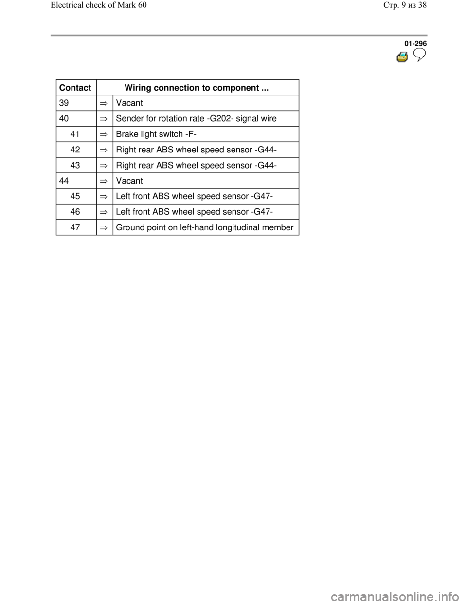
Contact
Wiring connection to component ...
39
Vacant
40
Sender for rotation rate -G202- signal wire
41
Brake light switch -F-
42
Right rear ABS wheel speed sensor -G44-
43
Right rear ABS wheel speed sensor -G44-
44
Vacant
45
Left front ABS wheel speed sensor -G47-
46
Left front ABS wheel speed sensor -G47-
47
Ground point on left-hand longitudinal member
Стр. 9из 38 Electrical check of Mark 60
Page 305 of 339
Downloaded from www.Manualslib.com manuals search engine 01-297
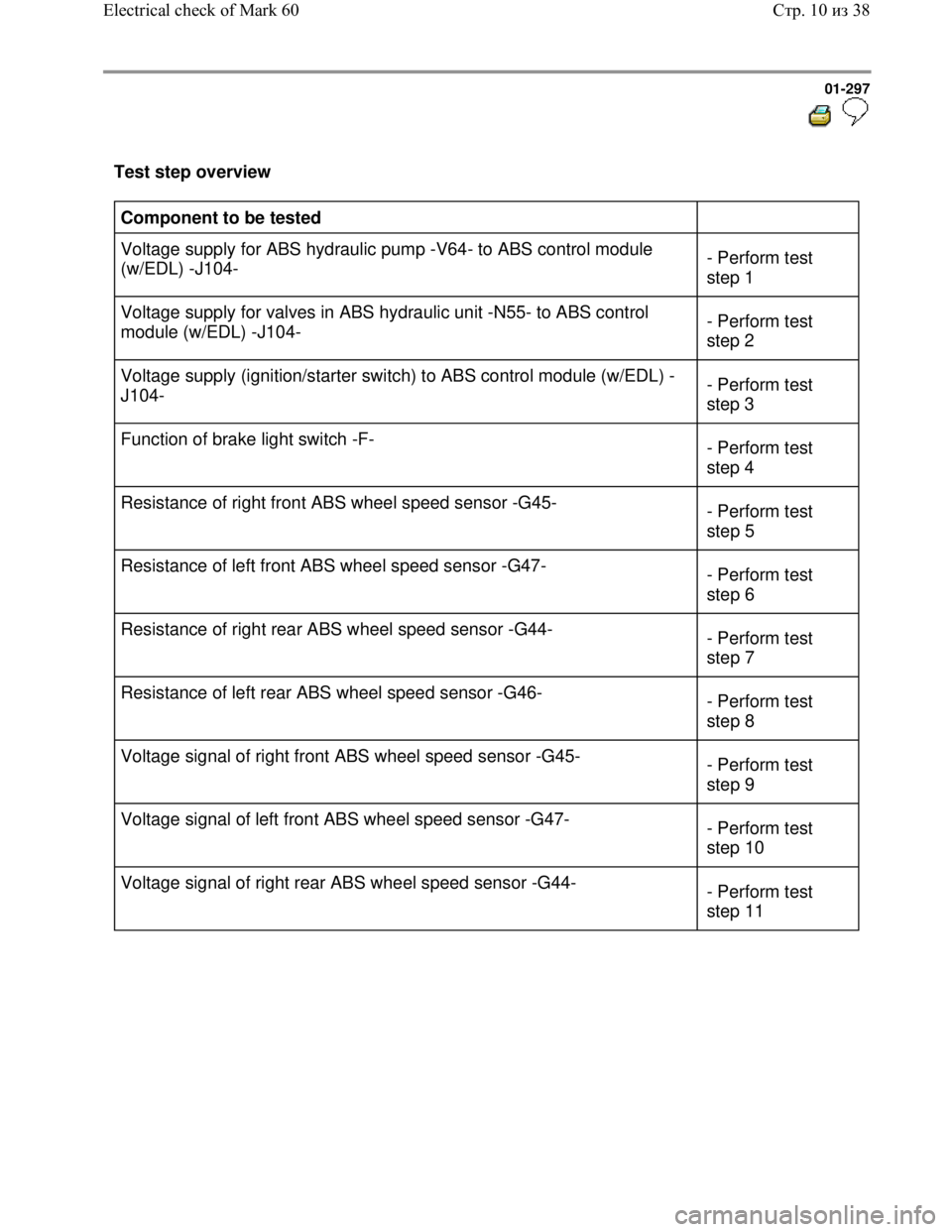
Test step overview
Component to be tested
Voltage supply for ABS hydraulic pump -V64- to ABS control module
(w/EDL) -J104- - Perform test
step 1
Voltage supply for valves in ABS hydraulic unit -N55- to ABS control
module (w/EDL) -J104- - Perform test
step 2
Voltage supply (ignition/starter switch) to ABS control module (w/EDL) -
J104- - Perform test
step 3
Function of brake light switch -F-
- Perform test
step 4
Resistance of right front ABS wheel speed sensor -G45-
- Perform test
step 5
Resistance of left front ABS wheel speed sensor -G47-
- Perform test
step 6
Resistance of right rear ABS wheel speed sensor -G44-
- Perform test
step 7
Resistance of left rear ABS wheel speed sensor -G46-
- Perform test
step 8
Voltage signal of right front ABS wheel speed sensor -G45-
- Perform test
step 9
Voltage signal of left front ABS wheel speed sensor -G47-
- Perform test
step 10
Voltage signal of right rear ABS wheel speed sensor -G44-
- Perform test
step 11
Стр. 10из 38 Electrical check of Mark 60
Page 306 of 339
Downloaded from www.Manualslib.com manuals search engine 01-298
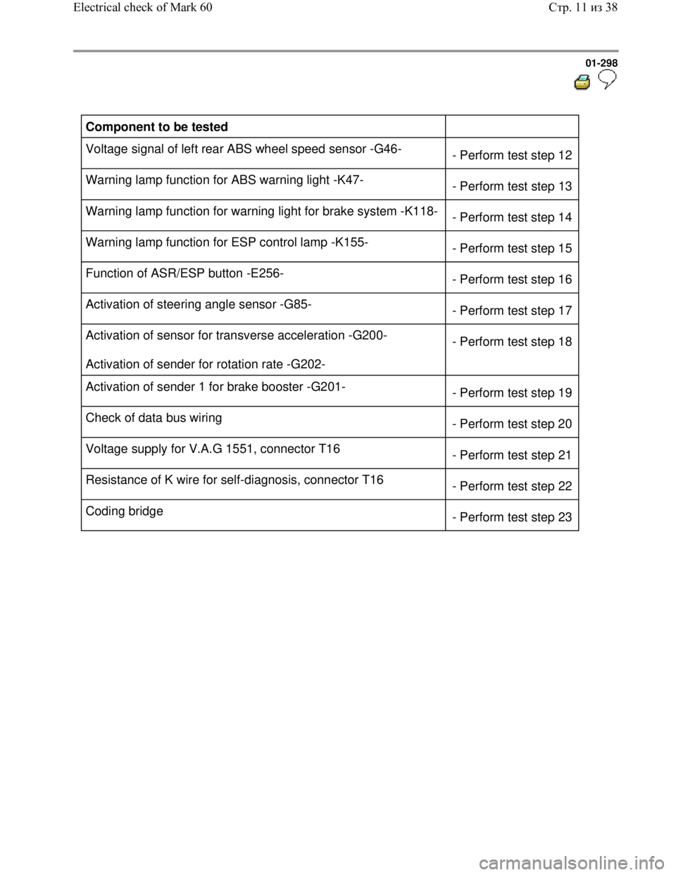
Component to be tested
Voltage signal of left rear ABS wheel speed sensor -G46-
- Perform test step 12
Warning lamp function for ABS warning light -K47-
- Perform test step 13
Warning lamp function for warning light for brake system -K118-
- Perform test step 14
Warning lamp function for ESP control lamp -K155-
- Perform test step 15
Function of ASR/ESP button -E256-
- Perform test step 16
Activation of steering angle sensor -G85-
- Perform test step 17
Activation of sensor for transverse acceleration -G200-
Activation of sender for rotation rate -G202- - Perform test step 18
Activation of sender 1 for brake booster -G201-
- Perform test step 19
Check of data bus wiring
- Perform test step 20
Voltage supply for V.A.G 1551, connector T16
- Perform test step 21
Resistance of K wire for self-diagnosis, connector T16
- Perform test step 22
Coding bridge
- Perform test step 23
Стр. 11из 38 Electrical check of Mark 60