front VOLKSWAGEN T-ROC 2021 Owner´s Manual
[x] Cancel search | Manufacturer: VOLKSWAGEN, Model Year: 2021, Model line: T-ROC, Model: VOLKSWAGEN T-ROC 2021Pages: 502, PDF Size: 9.42 MB
Page 344 of 502
Fit the connector ⇒ Fig. 168 ① on the bulb holder ⇒ Fig. 168 ②. The connector should
click into place.
Fit the cover in the wheel housing liner ⇒ Fig. 168 and lock it in position.
NOTICE
the headlight housing is seated properly in order to
prevent damage to the electrical system caused by water entering the system.
damaged.
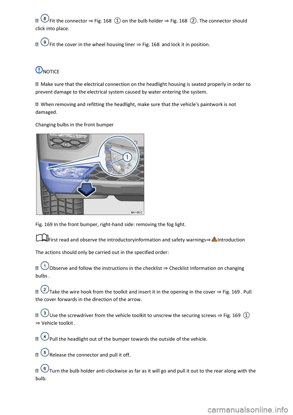
Changing bulbs in the front bumper
Fig. 169 In the front bumper, right-hand side: removing the fog light.
First read and observe the introductoryinformation and safety warnings⇒Introduction
The actions should only be carried out in the specified order:
Observe and follow the instructions in the checklist ⇒ Checklist Information on changing
bulbs .
Take the wire hook from the toolkit and insert it in the opening in the cover ⇒ Fig. 169 . Pull
the cover forwards in the direction of the arrow.
Use the screwdriver from the vehicle toolkit to unscrew the securing screws ⇒ Fig. 169 ①
⇒ Vehicle toolkit .
Pull the headlight out of the bumper towards the outside of the vehicle.
Release the connector and pull it off.
Turn the bulb holder anti-clockwise as far as it will go and pull it out to the rear along with the
bulb.
Page 347 of 502
There are other fuses in the vehicle in addition to those described in this chapter. These should be
changed only by a qualified workshop.
Fuses in the dash panel
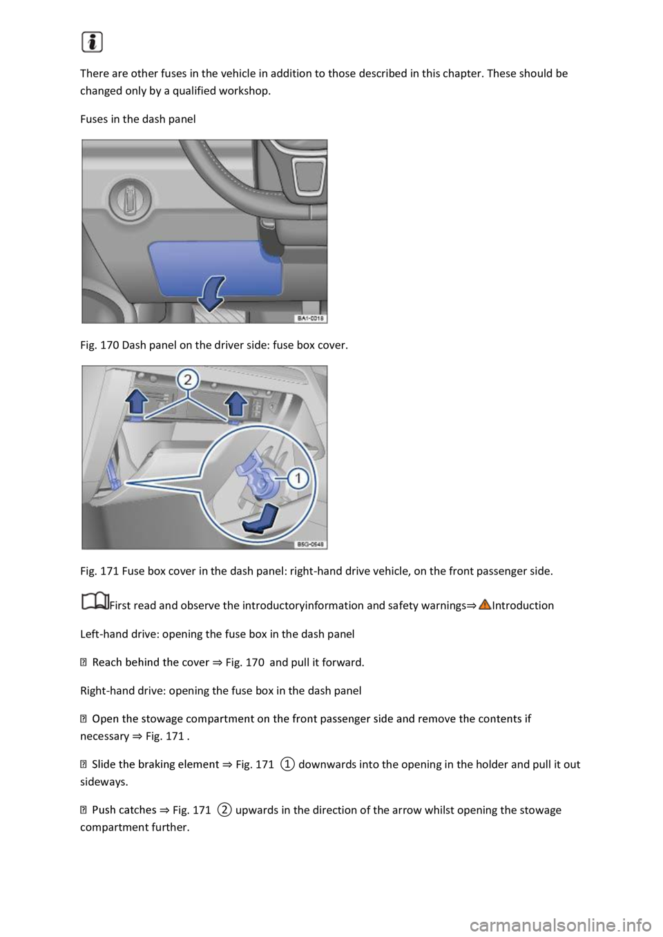
Fig. 170 Dash panel on the driver side: fuse box cover.
Fig. 171 Fuse box cover in the dash panel: right-hand drive vehicle, on the front passenger side.
First read and observe the introductoryinformation and safety warnings⇒Introduction
Left-hand drive: opening the fuse box in the dash panel
⇒ Fig. 170 and pull it forward.
Right-hand drive: opening the fuse box in the dash panel
necessary ⇒ Fig. 171 .
⇒ Fig. 171 ① downwards into the opening in the holder and pull it out
sideways.
⇒ Fig. 171 ② upwards in the direction of the arrow whilst opening the stowage
compartment further.
Page 350 of 502
1) Note installation position. Factory-fitted fuse location as shown in illustration ⇒ Fig. 173 .
Fuse tables for fuses in the engine compartment
First read and observe the introductoryinformation and safety warnings⇒Introduction
The table shows the fuse locations of the electrical consumers relevant for the driver. The first
column in the table contains the location. The other columns contain the fuse type, the amp rating
and the consumer protected by the fuse.
Depending on the market and specification of your vehicle, the fuse numbers and positions may
differ to those given in the table. If necessary, ask your Volkswagen dealership for the exact fuse
assignment.
F65 amps, ATO®, brake light sensor.F1440 amps, JCASE®, windscreen heating.F1515 amps, ATO®,
horn.F1930 amps, ATO®, front wipers.F3720 amps, ATO®, auxiliary heater.
Changing a blown fuse
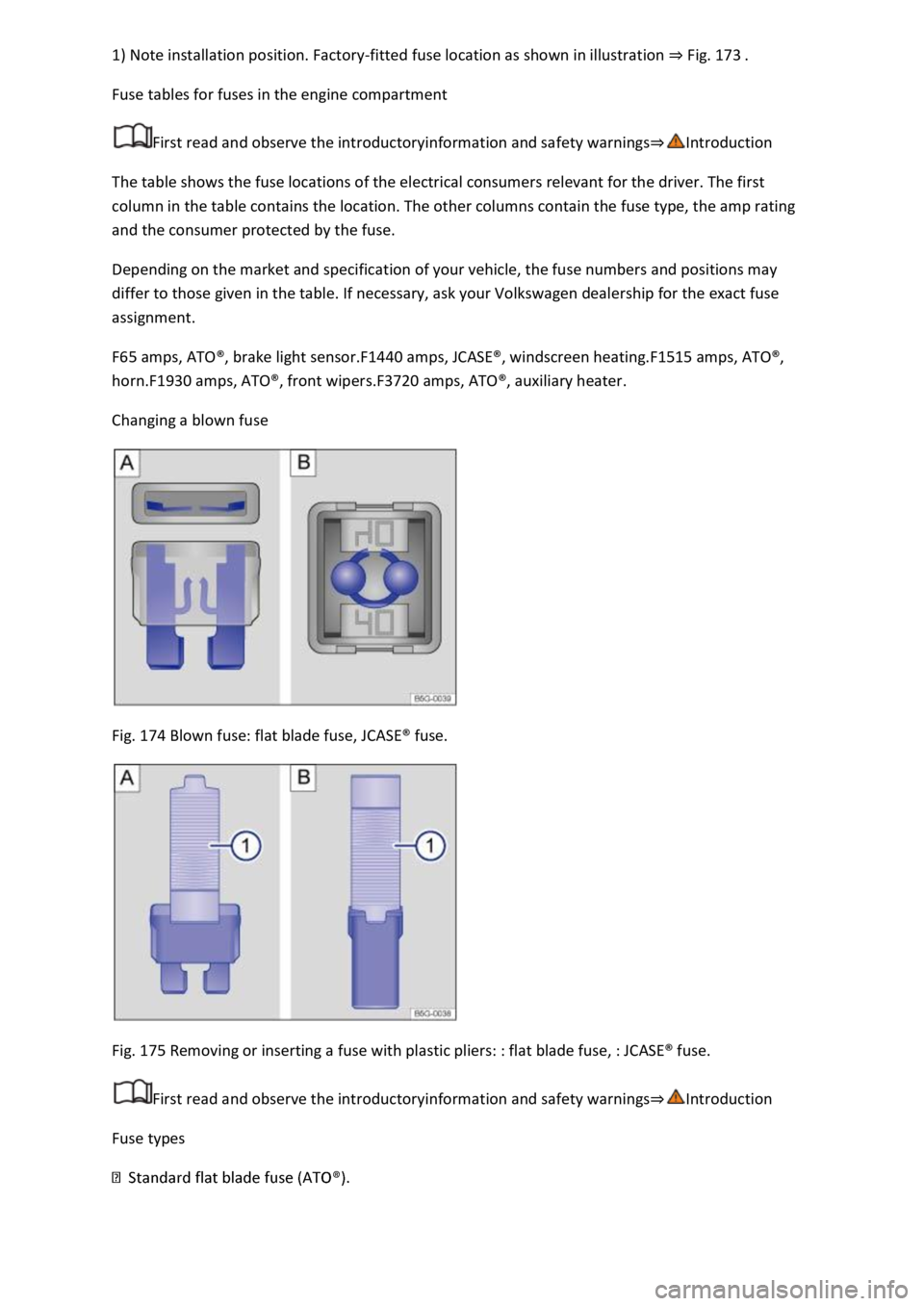
Fig. 174 Blown fuse: flat blade fuse, JCASE® fuse.
Fig. 175 Removing or inserting a fuse with plastic pliers: : flat blade fuse, : JCASE® fuse.
First read and observe the introductoryinformation and safety warnings⇒Introduction
Fuse types
Page 356 of 502
⇒ Tow-starting
⇒ Towing
⇒ Fitting the rear towing eye
⇒ Fitting the front towing eye
Towing requires some experience, especially when using a tow rope. Both drivers should be familiar
with the technique required for towing. Inexperienced drivers should not attempt to tow.
Ensure that no excessive pulling forces occur and take care to avoid jerking movements. When
towing offroad, there is always a risk of overloading the anchorage points.
Observe any legal requirements when towing or tow-starting.
Tow-starting
Tow-starting describes the procedure for starting the vehicle by moving it using another towing
vehicle.
The vehicle can be tow-started with a tow-bar or a tow-rope.
Towing
Towing is where a vehicle that cannot be driven is pulled with the aid of another vehicle.
The vehicle can be towed with a tow-bar or a tow-rope. When the engine is stopped, the gearbox is
not lubricated sufficiently at higher speeds and over long distances:
km/h (30 mph).
km.
Tow rope, tow bar
It is easier and safer to tow a vehicle with a tow bar. Use a tow rope only if you do not have a tow
bar.
The tow rope should be slightly elastic to reduce the strain on both vehicles. It is advisable to use a
tow rope made of synthetic fibre or similarly elastic material.
Towing with a tow truck
If your vehicle is to be raised on one axle for towing, this may only be done using the following axles
according to the gearbox/drive combination:
Front-wheel drive
Manual gearboxFront or rear axleAutomatic gearboxFront axle
WARNING
If a vehicle is being towed, the vehicle handling and braking efficiency will change significantly.
Page 358 of 502

For technical reasons, your vehicle must not be tow-started. Attempt to start the engine by jump
starting ⇒ Jump starting .
Vehicles with a manual gearbox:
Tow-starting is generally not recommended. If the engine does not start, first attempt to start the
engine by jump starting ⇒ Jump starting . Please note that the maximum tow-starting distance for
petrol engines is 50 m.
-rope or the tow-bar only to the towing eyes provided ⇒ Fitting the rear towing
eye or ⇒ Fitting the front towing eye .
warning lights.
utral to prevent
driving into the towing vehicle.
NOTICE
When tow-starting, unburnt fuel can enter the catalytic converter and damage it.
Towing
First read and observe the introductoryinformation and safety warnings⇒Introduction
Preparations
h the tow-rope or the tow-bar only to the towing eyes provided ⇒ Fitting the rear towing
eye or ⇒ Fitting the front towing eye or to the towing bracket ⇒ Trailer towing .
-rope is not twisted. Otherwise a towing eye may become unscrewed
during towing.
regulations to the contrary.
Pulling vehicle (front)
tow-rope must be taut before you drive off properly.
Page 360 of 502
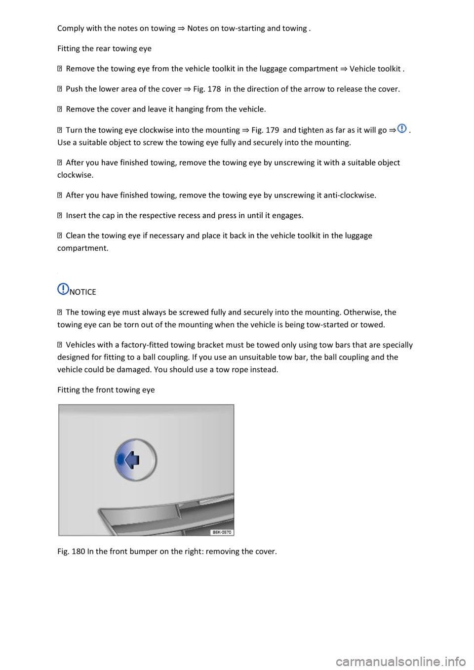
Comply with the notes on towing ⇒ Notes on tow-starting and towing .
Fitting the rear towing eye
⇒ Vehicle toolkit .
area of the cover ⇒ Fig. 178 in the direction of the arrow to release the cover.
⇒ Fig. 179 and tighten as far as it will go ⇒ .
Use a suitable object to screw the towing eye fully and securely into the mounting.
clockwise.
-clockwise.
compartment.
NOTICE
urely into the mounting. Otherwise, the
towing eye can be torn out of the mounting when the vehicle is being tow-started or towed.
-fitted towing bracket must be towed only using tow bars that are specially
designed for fitting to a ball coupling. If you use an unsuitable tow bar, the ball coupling and the
vehicle could be damaged. You should use a tow rope instead.
Fitting the front towing eye
Fig. 180 In the front bumper on the right: removing the cover.
Page 361 of 502
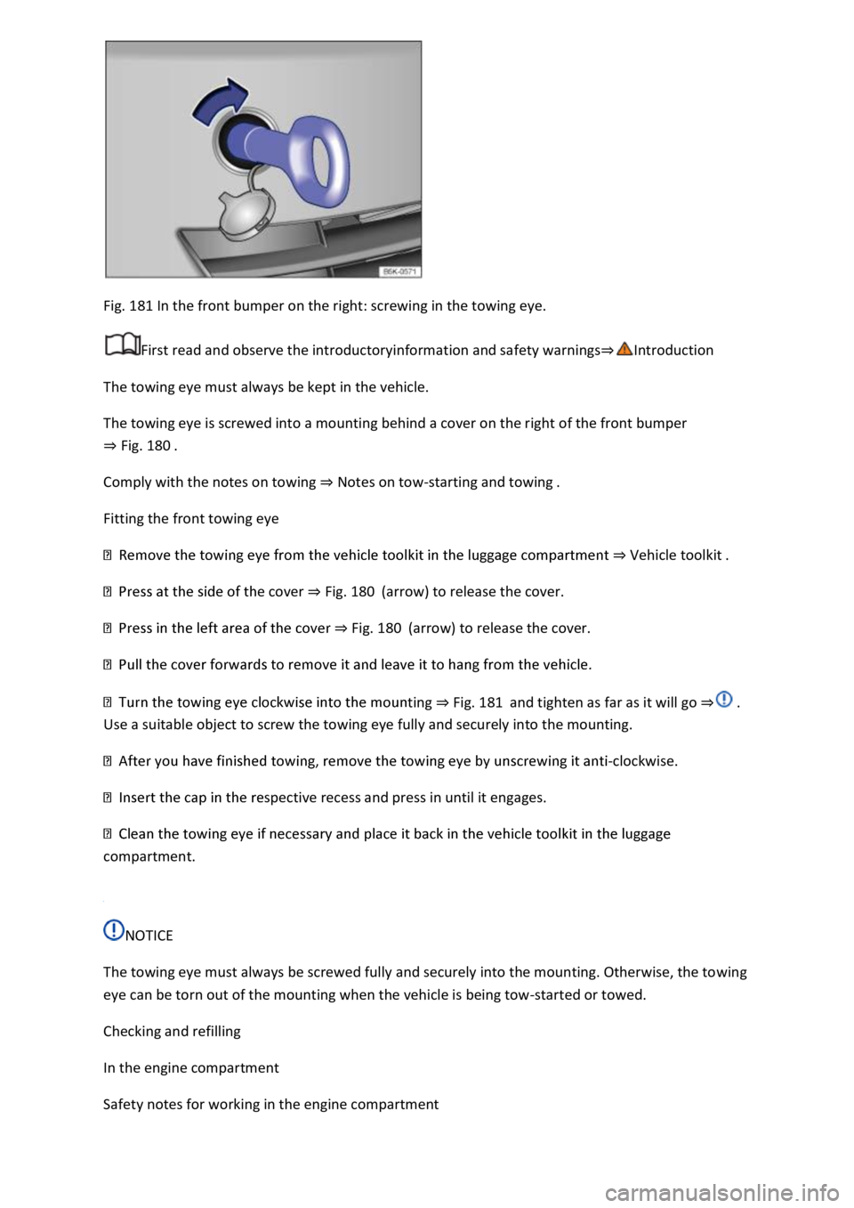
Fig. 181 In the front bumper on the right: screwing in the towing eye.
First read and observe the introductoryinformation and safety warnings⇒Introduction
The towing eye must always be kept in the vehicle.
The towing eye is screwed into a mounting behind a cover on the right of the front bumper
⇒ Fig. 180 .
Comply with the notes on towing ⇒ Notes on tow-starting and towing .
Fitting the front towing eye
⇒ Vehicle toolkit .
e cover ⇒ Fig. 180 (arrow) to release the cover.
⇒ Fig. 180 (arrow) to release the cover.
ting ⇒ Fig. 181 and tighten as far as it will go ⇒ .
Use a suitable object to screw the towing eye fully and securely into the mounting.
-clockwise.
spective recess and press in until it engages.
compartment.
NOTICE
The towing eye must always be screwed fully and securely into the mounting. Otherwise, the towing
eye can be torn out of the mounting when the vehicle is being tow-started or towed.
Checking and refilling
In the engine compartment
Safety notes for working in the engine compartment
Page 369 of 502
-original containers as
people finding these containers could drink them.
es.
-ventilated
area.
r or other volatile fluids for vehicle care.
These substances are toxic and highly flammable. They could cause fires and explosions.
NOTICE
this can result in serious malfunctions and engine damage.
-on parts in front of the air intake reduce the cooling effect of the
coolant. The engine may overheat at high ambient temperatures and high engine loads.
Leaking service fluids can pollute the environment. Spilt service fluids must be collected in suitable
containers and disposed of properly and with respect for the environment.
Washer fluid
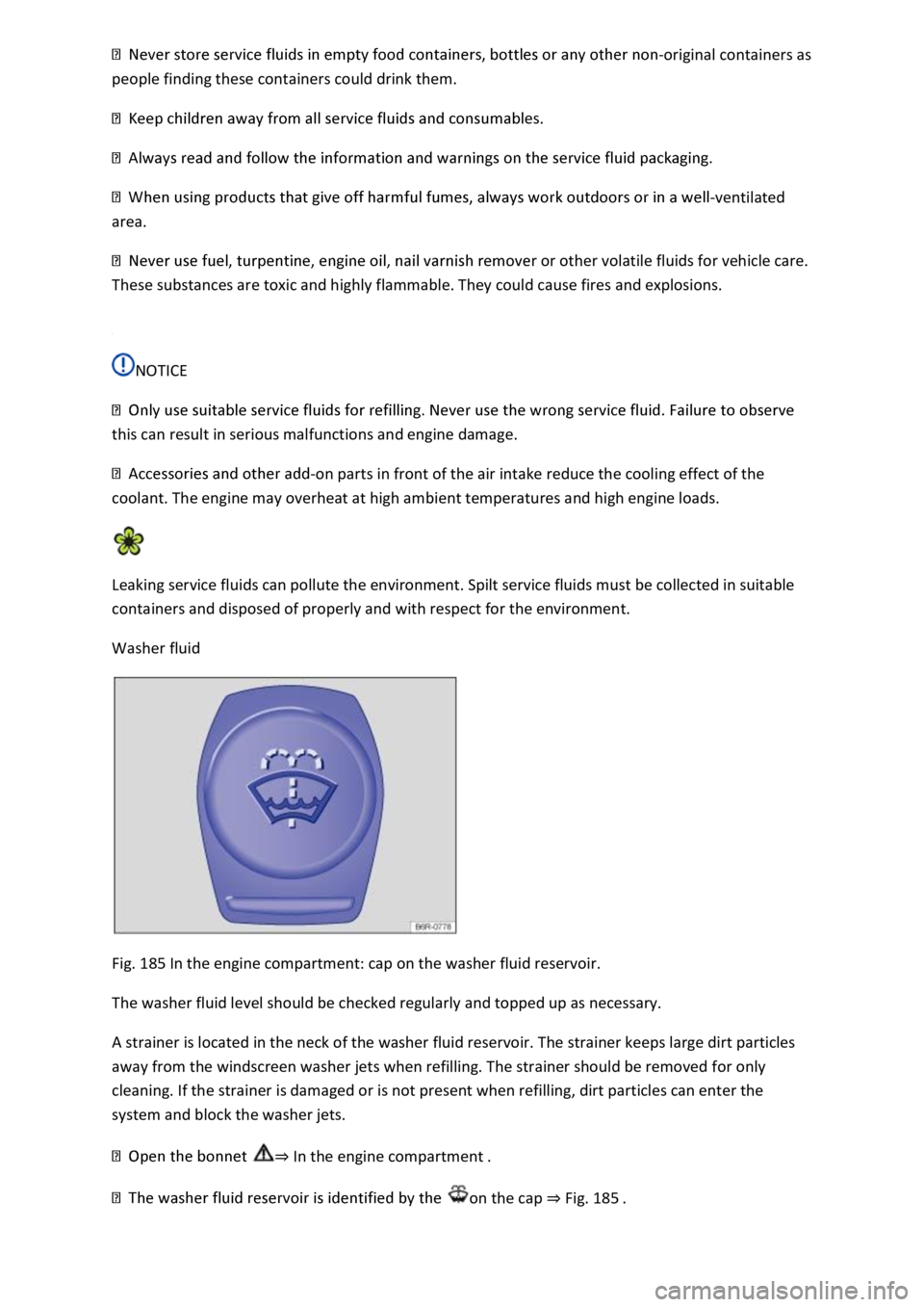
Fig. 185 In the engine compartment: cap on the washer fluid reservoir.
The washer fluid level should be checked regularly and topped up as necessary.
A strainer is located in the neck of the washer fluid reservoir. The strainer keeps large dirt particles
away from the windscreen washer jets when refilling. The strainer should be removed for only
cleaning. If the strainer is damaged or is not present when refilling, dirt particles can enter the
system and block the washer jets.
⇒ In the engine compartment .
on the cap ⇒ Fig. 185 .
Page 398 of 502
Replacing tyres
lace tyres at least on an axle-by-axle basis ⇒ .
type.
-approved tyres.
Re-synchronising the Tyre Pressure Loss Indicator
The Tyre Pressure Loss Indicator must be re-synchronised each time one or more wheels is changed.
This also applies if the wheels have been swapped, e.g. from the front to the rear ⇒ Tyre monitoring
system .
WARNING
Aggressive liquids and other substances can cause visible and invisible damage to the tyres, which
can cause the tyre to burst.
from the tyres.
WARNING
Even if they have not been used, old tyres can suddenly lose pressure or burst, especially at high
speeds, and thus cause accidents and serious injuries.
ith
extra care at all times.
WARNING
New tyres must be run in as they initially have reduced grip and braking efficiency.
km in order to prevent accidents and serious injury.
WARNING
Wheels must have the necessary clearance. If the wheels do not have the necessary clearance, the
tyre could rub on parts of the running gear, vehicle body and the brake lines. This can lead to a fault
in the brake system and to tread separation and thus to a tyre bursting.
and must not rub on any vehicle body parts.
Page 401 of 502
First read and observe the introductoryinformation and safety warnings⇒Introduction
Information on the sticker ⇒ Fig. 194 :
Tyre pressure for the tyres on the front axle.
Tyre pressure for the tyres on the rear axle.
Note: check the tyre pressure when the tyres are cold.
Tyre pressure for partial load.
Vehicle-dependent: comfort tyre pressure for partial load.
Tyre pressure for full load.
Tyre pressure level for the spare or temporary spare wheel.
The sticker provides the correct tyre pressure for approved tyres and is located either on the driver
door pillar ⇒ Fig. 195 or inside the tank flap.
The appearance of the sticker may differ between vehicles. It may include additional tyre sizes.
The wrong tyre pressure will have a negative effect on the vehicle handling and leads to high levels
of wear or even a burst tyre ⇒ . The correct tyre pressure is particularly important at high speeds.
Comfort tyre pressure
Depending on the vehicle, the tyre pressure sticker may show details of a comfort tyre pressure
⇒ Fig. 194③ . The comfort tyre pressure allows increased driving comfort. Fuel consumption may
increase when driving with comfort tyre pressure.
Checking the tyre pressure
tyres. Tyre pressure is always higher in warm tyres than it is in cold tyres. For this reason, never
reduce the pressure in warm tyres to adjust the tyre pressure.
⇒ Fig. 194④ .
and observe the
information on the tyre monitoring system.
which is given on the sidewall of the tyre.
WARNING