VOLVO V60 2014 Owners Manual
Manufacturer: VOLVO, Model Year: 2014, Model line: V60, Model: VOLVO V60 2014Pages: 442, PDF Size: 13.85 MB
Page 361 of 442
10 Maintenance and service
10
359
LightingWAType
–––
Reversing lamp21P21W LL
Rear fog lamp21H21W LL
A
Watt
Related information
• Lamp replacement (p. 352)
• Lamp replacement - location of rear lamps (p. 357)
• Lamp replacement - vanity mirror lighting(p. 358)
Wiper blades
The wiper blades sweep water away from the windscreen and rear window. Together withthe washer fluid they clean the windows andensure visibility for driving. The windscreen wiper blades must be in serv- ice position when they are to be replaced.
Service position
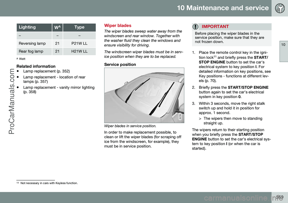
Wiper blades in service position.
In order to make replacement possible, to clean or lift the wiper blades (for scraping office from the windscreen, for example), theymust be in service position.
IMPORTANT
Before placing the wiper blades in the service position, make sure that they arenot frozen down.
1. Place the remote control key in the igni- tion lock 11
and briefly press the START/
STOP ENGINE button to set the car's
electrical system to key position I. For
detailed information on key positions, see Key positions - functions at different lev-els (p. 70).
2. Briefly press the START/STOP ENGINE
button again to set the car’s electricalsystem in key position 0.
3. Within 3 seconds, move the right stalk switch up and hold it in position forapprox. 1 second.
> The wipers then move to standingstraight up.
The wipers return to their starting position when you briefly press the START/STOP
ENGINE button to set the car’s electrical sys-
tem to key position I (or when the car is
started).
11 Not necessary in cars with Keyless function.
ProCarManuals.co’
Page 362 of 442
||
10 Maintenance and service
10
360
IMPORTANT
If the wiper arms in service position have been folded up from the windscreen, theymust be folded back down onto the wind-screen before the wipers are allowed toreturn to their starting position. This is toavoid scraping the paint on the bonnet.
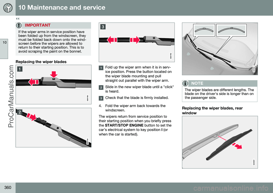
Replacing the wiper blades
Fold up the wiper arm when it is in serv- ice position. Press the button located onthe wiper blade mounting and pullstraight out parallel with the wiper arm.
Slide in the new wiper blade until a "click" is heard.
Check that the blade is firmly installed.
4. Fold the wiper arm back towards the windscreen.
The wipers return from service position to their starting position when you briefly pressthe START/STOP ENGINE button to set the
car’s electrical system to key position I (or
when the car is started).
NOTE
The wiper blades are different lengths. The blade on the driver's side is longer than onthe passenger side.
Replacing the wiper blades, rear window
ProCarManuals.com
Page 363 of 442
10 Maintenance and service
10
361
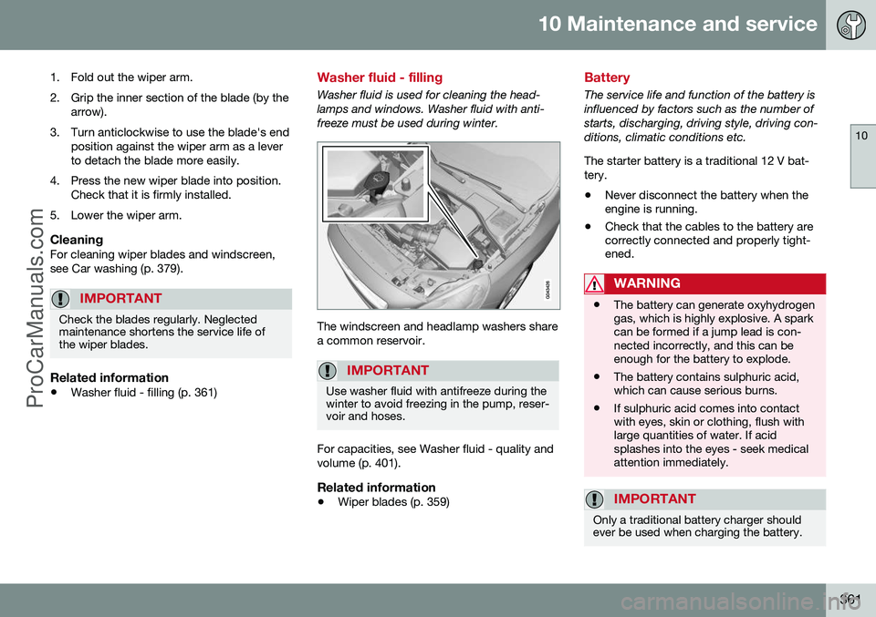
1. Fold out the wiper arm.
2. Grip the inner section of the blade (by the arrow).
3. Turn anticlockwise to use the blade's end position against the wiper arm as a lever to detach the blade more easily.
4. Press the new wiper blade into position. Check that it is firmly installed.
5. Lower the wiper arm.
CleaningFor cleaning wiper blades and windscreen,see Car washing (p. 379).
IMPORTANT
Check the blades regularly. Neglected maintenance shortens the service life ofthe wiper blades.
Related information
• Washer fluid - filling (p. 361)
Washer fluid - filling
Washer fluid is used for cleaning the head- lamps and windows. Washer fluid with anti-freeze must be used during winter.
The windscreen and headlamp washers share a common reservoir.
IMPORTANT
Use washer fluid with antifreeze during the winter to avoid freezing in the pump, reser-voir and hoses.
For capacities, see Washer fluid - quality and volume (p. 401).
Related information
•Wiper blades (p. 359)
Battery
The service life and function of the battery is influenced by factors such as the number ofstarts, discharging, driving style, driving con-ditions, climatic conditions etc. The starter battery is a traditional 12 V bat- tery.
• Never disconnect the battery when the engine is running.
• Check that the cables to the battery arecorrectly connected and properly tight-ened.
WARNING
•The battery can generate oxyhydrogen gas, which is highly explosive. A sparkcan be formed if a jump lead is con-nected incorrectly, and this can beenough for the battery to explode.
• The battery contains sulphuric acid,which can cause serious burns.
• If sulphuric acid comes into contactwith eyes, skin or clothing, flush withlarge quantities of water. If acidsplashes into the eyes - seek medicalattention immediately.
IMPORTANT
Only a traditional battery charger should ever be used when charging the battery.
ProCarManuals.co’
Page 364 of 442
||
10 Maintenance and service
10
362
IMPORTANT
If the following instruction is not observed then the energy saving function for info-tainment may be temporarily disengaged,and/or the message in the information dis-play about the main battery's state ofcharge may be temporarily inapplicable,following the connection of an externalbattery or battery charger:
• The negative battery terminal on the car's starter battery must
never be
used for connecting an external bat-tery or battery charger - only the car
chassis may be used as the ground-
ing point.
See Jump starting with battery (p. 270) for a description of how the cable clampsmust be attached.
NOTE
The life of the battery is shortened if it becomes discharged repeatedly. The life of the battery is affected by several factors, including driving conditions andclimate. Battery starting capacity decrea-ses gradually with time and thereforeneeds to be recharged if the car is notused for a longer time or when it is onlydriven short distances. Extreme cold fur-ther limits starting capacity. To maintain the battery in good condition, at least 15 minutes of driving/week is rec-ommended or that the battery is con-nected to a battery charger with automatictrickle charging. A battery that is kept fully charged has a maximum service life.
Related information
• Battery - symbols (p. 362)
• Starter battery - replacement (p. 363)
• Battery - Start/Stop (p. 365)
Battery - symbols
There are information and warning symbols on the battery.
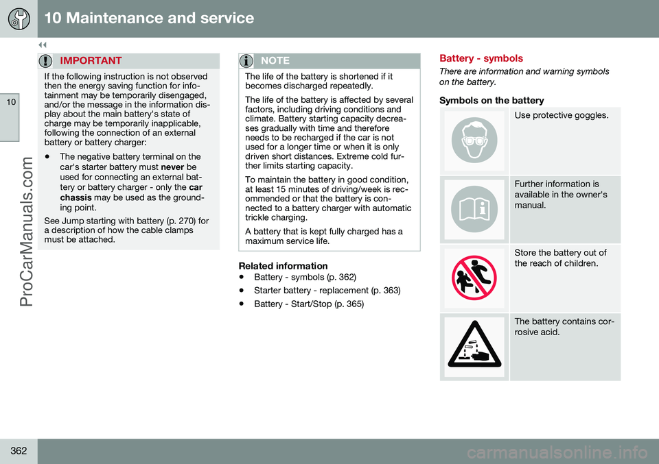
Symbols on the battery
Use protective goggles.
Further information is available in the owner'smanual.
Store the battery out of the reach of children.
The battery contains cor- rosive acid.
ProCarManuals.co’
Page 365 of 442
10 Maintenance and service
10
363
Avoid sparks and naked flames.
Risk of explosion.
Must be taken for recy- cling.
NOTE
An expended battery must be recycled in an environmentally safe manner as it con-tains lead.
Related information
•Battery (p. 361)
Starter battery - replacement
The starter battery in the car can be replaced without the help of a workshop. The starter battery is a traditional 12 V bat- tery.
RemovalFirst of all
: Take the remote control key from
the ignition switch and wait at least 5 minutesbefore any electrical connections are touched- this is because the car's electrical systemneeds to store the necessary information tocontrol modules.
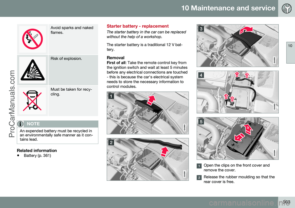
Open the clips on the front cover and remove the cover.
Release the rubber moulding so that the rear cover is free.
ProCarManuals.co’
Page 366 of 442
||
10 Maintenance and service
10
364* Option/accessory, for more information, see Introduction.
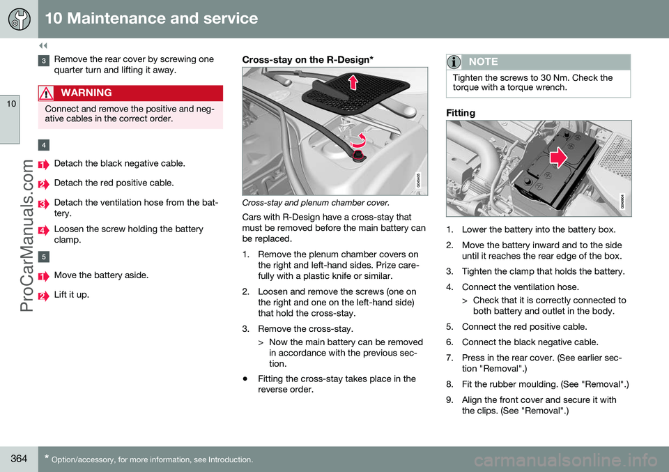
Remove the rear cover by screwing one quarter turn and lifting it away.
WARNING
Connect and remove the positive and neg- ative cables in the correct order.
Detach the black negative cable.
Detach the red positive cable.
Detach the ventilation hose from the bat- tery.
Loosen the screw holding the battery clamp.
Move the battery aside.
Lift it up.
Cross-stay on the R-Design*
Cross-stay and plenum chamber cover.
Cars with R-Design have a cross-stay that must be removed before the main battery canbe replaced.
1. Remove the plenum chamber covers on the right and left-hand sides. Prize care- fully with a plastic knife or similar.
2. Loosen and remove the screws (one on the right and one on the left-hand side)that hold the cross-stay.
3. Remove the cross-stay. > Now the main battery can be removedin accordance with the previous sec-tion.
• Fitting the cross-stay takes place in the reverse order.
NOTE
Tighten the screws to 30 Nm. Check the torque with a torque wrench.
Fitting
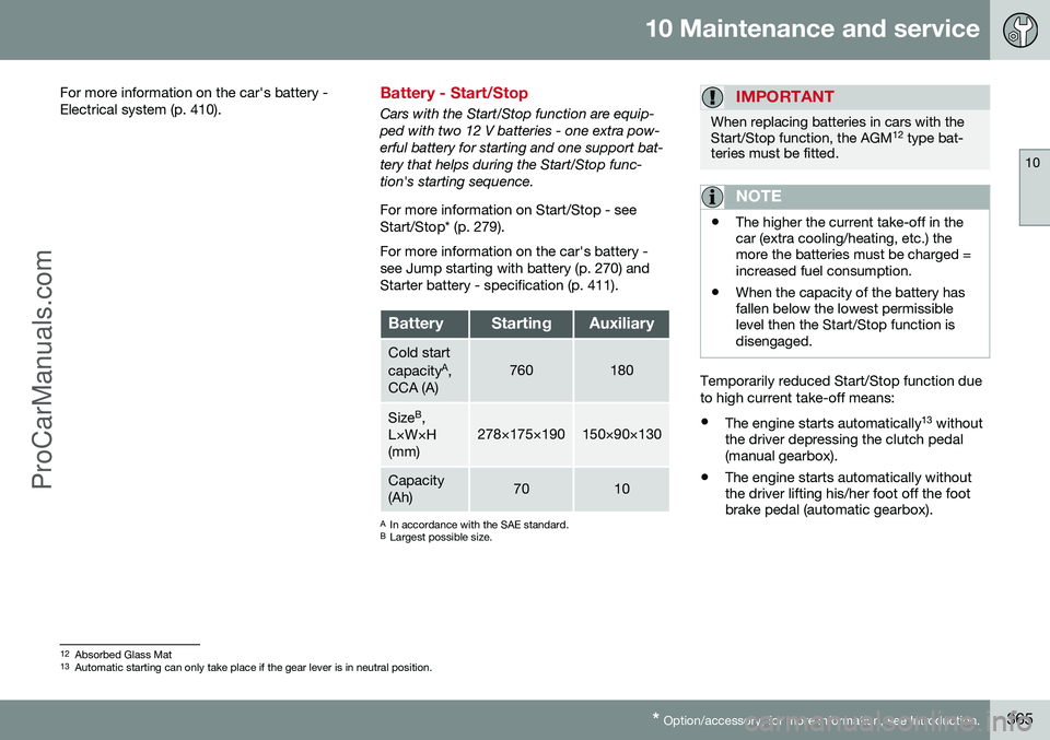
1. Lower the battery into the battery box.
2. Move the battery inward and to the side
until it reaches the rear edge of the box.
3. Tighten the clamp that holds the battery.
4. Connect the ventilation hose. > Check that it is correctly connected toboth battery and outlet in the body.
5. Connect the red positive cable.
6. Connect the black negative cable.
7. Press in the rear cover. (See earlier sec- tion "Removal".)
8. Fit the rubber moulding. (See "Removal".)
9. Align the front cover and secure it with the clips. (See "Removal".)
ProCarManuals.co’
Page 367 of 442
10 Maintenance and service
10
* Option/accessory, for more information, see Introduction.365
For more information on the car's battery - Electrical system (p. 410).
Battery - Start/Stop
Cars with the Start/Stop function are equip- ped with two 12 V batteries - one extra pow-erful battery for starting and one support bat-tery that helps during the Start/Stop func-tion's starting sequence. For more information on Start/Stop - see Start/Stop* (p. 279). For more information on the car's battery - see Jump starting with battery (p. 270) andStarter battery - specification (p. 411).
BatteryStartingAuxiliary
Cold start capacity
A
,
CCA (A)760180
Size B
,
L×W×H (mm)278×175×190150×90×130
Capacity (Ah)7010
A In accordance with the SAE standard.
B Largest possible size.
IMPORTANT
When replacing batteries in cars with the Start/Stop function, the AGM 12
type bat-
teries must be fitted.
NOTE
• The higher the current take-off in the car (extra cooling/heating, etc.) themore the batteries must be charged =increased fuel consumption.
• When the capacity of the battery hasfallen below the lowest permissiblelevel then the Start/Stop function isdisengaged.
Temporarily reduced Start/Stop function due to high current take-off means: •
The engine starts automatically 13
without
the driver depressing the clutch pedal (manual gearbox).
• The engine starts automatically withoutthe driver lifting his/her foot off the footbrake pedal (automatic gearbox).
12
Absorbed Glass Mat
13 Automatic starting can only take place if the gear lever is in neutral position.
ProCarManuals.co’
Page 368 of 442
||
10 Maintenance and service
10
366
Location of the batteries
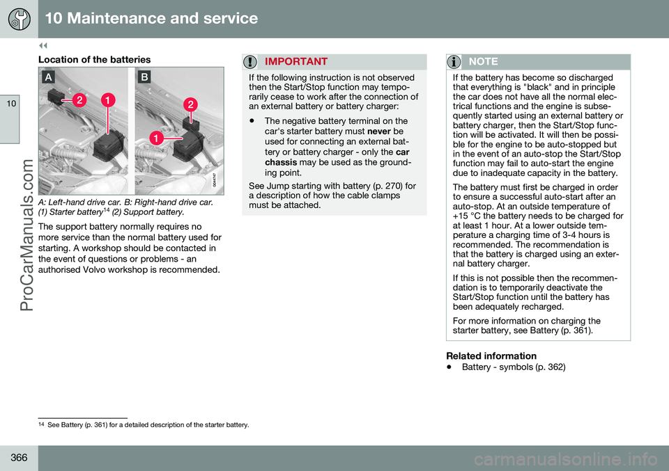
A: Left-hand drive car. B: Right-hand drive car. (1) Starter battery14
(2) Support battery.
The support battery normally requires no more service than the normal battery used forstarting. A workshop should be contacted inthe event of questions or problems - anauthorised Volvo workshop is recommended.
IMPORTANT
If the following instruction is not observed then the Start/Stop function may tempo-rarily cease to work after the connection ofan external battery or battery charger:
• The negative battery terminal on the car's starter battery must
never be
used for connecting an external bat-tery or battery charger - only the car
chassis may be used as the ground-
ing point.
See Jump starting with battery (p. 270) for a description of how the cable clampsmust be attached.
NOTE
If the battery has become so discharged that everything is "black" and in principlethe car does not have all the normal elec-trical functions and the engine is subse-quently started using an external battery orbattery charger, then the Start/Stop func-tion will be activated. It will then be possi-ble for the engine to be auto-stopped butin the event of an auto-stop the Start/Stopfunction may fail to auto-start the enginedue to inadequate capacity in the battery. The battery must first be charged in order to ensure a successful auto-start after anauto-stop. At an outside temperature of+15 °C the battery needs to be charged forat least 1 hour. At a lower outside tem-perature a charging time of 3-4 hours isrecommended. The recommendation isthat the battery is charged using an exter-nal battery charger. If this is not possible then the recommen- dation is to temporarily deactivate theStart/Stop function until the battery hasbeen adequately recharged. For more information on charging the starter battery, see Battery (p. 361).
Related information
• Battery - symbols (p. 362)
14
See Battery (p. 361) for a detailed description of the starter battery.
ProCarManuals.co’
Page 369 of 442
10 Maintenance and service
10
367
Fuses - general
All electrical functions and components are protected by a number of fuses in order toprotect the car's electrical system from dam-age by short circuiting or overloading. If an electrical component or function does not work, it may be because the component'sfuse was temporarily overloaded and failed. Ifthe same fuse fails repeatedly then there is afault in the circuit. Volvo recommends thatyou visit an authorised Volvo workshop forchecking.
Changing1. Look in the fuse diagram to locate thefuse.
2. Pull out the fuse and check from the side to see whether the curved wire hasblown.
3. If this is the case, replace it with a new fuse of the same colour and amperage.
WARNING
Never use a foreign object or a fuse with an amperage higher than that specifiedwhen replacing a fuse. This could causesignificant damage to the electrical systemand possibly lead to fire.
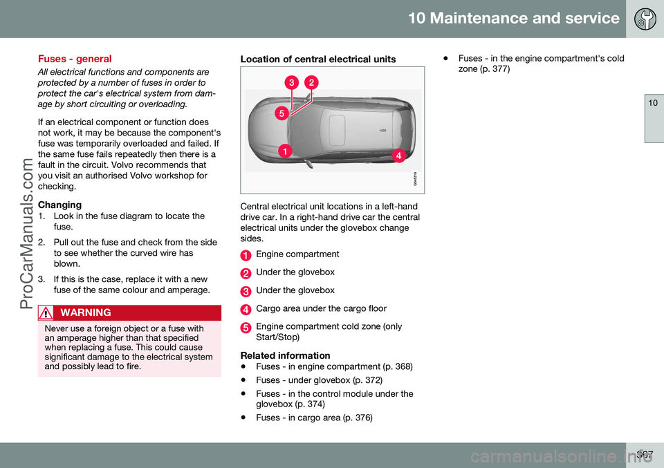
Location of central electrical units
Central electrical unit locations in a left-hand drive car. In a right-hand drive car the centralelectrical units under the glovebox changesides.
Engine compartment
Under the glovebox
Under the glovebox
Cargo area under the cargo floor
Engine compartment cold zone (only Start/Stop)
Related information
• Fuses - in engine compartment (p. 368)
• Fuses - under glovebox (p. 372)
• Fuses - in the control module under the glovebox (p. 374)
• Fuses - in cargo area (p. 376) •
Fuses - in the engine compartment's coldzone (p. 377)
ProCarManuals.co’
Page 370 of 442
10 Maintenance and service
10
368
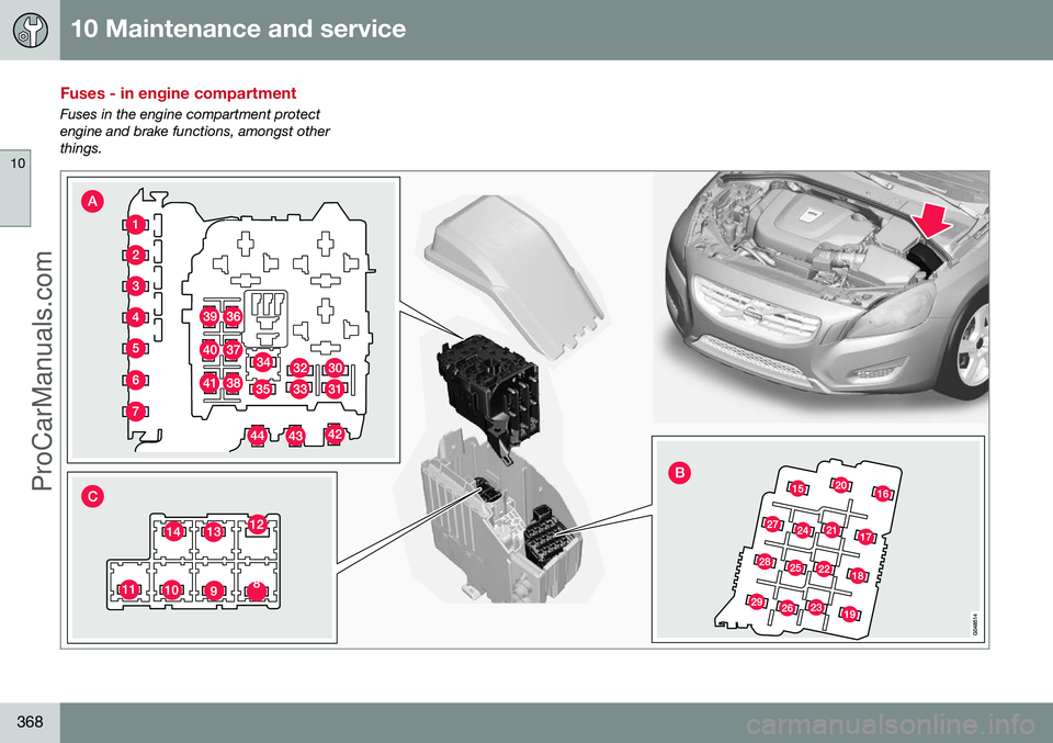
Fuses - in engine compartment
Fuses in the engine compartment protect engine and brake functions, amongst otherthings.
ProCarManuals.com