warning VOLVO V60 2014 Workshop Manual
[x] Cancel search | Manufacturer: VOLVO, Model Year: 2014, Model line: V60, Model: VOLVO V60 2014Pages: 442, PDF Size: 13.85 MB
Page 124 of 442
04 Climate control
04
122* Option/accessory, for more information, see Introduction.
Heated front seats*
The front seat heating has three positions for increasing the comfort for driver and passen-ger when it is cold.
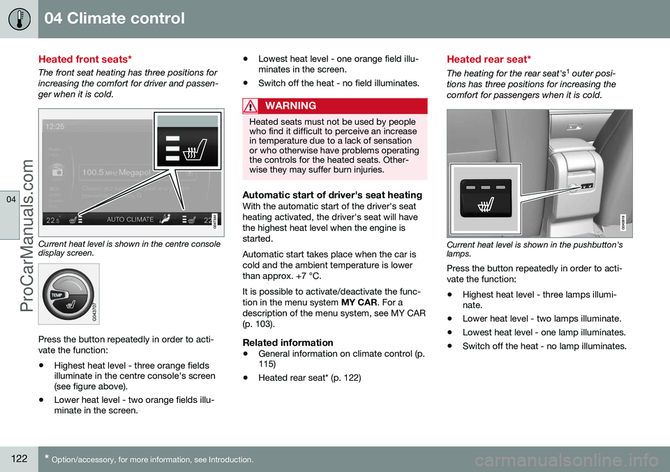
Current heat level is shown in the centre console display screen.
Press the button repeatedly in order to acti- vate the function:
• Highest heat level - three orange fields illuminate in the centre console's screen(see figure above).
• Lower heat level - two orange fields illu-minate in the screen. •
Lowest heat level - one orange field illu-minates in the screen.
• Switch off the heat - no field illuminates.
WARNING
Heated seats must not be used by people who find it difficult to perceive an increasein temperature due to a lack of sensationor who otherwise have problems operatingthe controls for the heated seats. Other-wise they may suffer burn injuries.
Automatic start of driver's seat heatingWith the automatic start of the driver's seat heating activated, the driver's seat will havethe highest heat level when the engine isstarted. Automatic start takes place when the car is cold and the ambient temperature is lowerthan approx. +7 °C. It is possible to activate/deactivate the func- tion in the menu system
MY CAR. For a
description of the menu system, see MY CAR(p. 103).
Related information
• General information on climate control (p. 115)
• Heated rear seat* (p. 122)
Heated rear seat*
The heating for the rear seat's 1
outer posi-
tions has three positions for increasing the comfort for passengers when it is cold.
Current heat level is shown in the pushbutton's lamps. Press the button repeatedly in order to acti- vate the function:
• Highest heat level - three lamps illumi- nate.
• Lower heat level - two lamps illuminate.
• Lowest heat level - one lamp illuminates.
• Switch off the heat - no lamp illuminates.
ProCarManuals.co’
Page 125 of 442
04 Climate control
04
* Option/accessory, for more information, see Introduction.123
WARNING
Heated seats must not be used by people who find it difficult to perceive an increasein temperature due to a lack of sensationor who otherwise have problems operatingthe controls for the heated seats. Other-wise they may suffer burn injuries.
Related information
• General information on climate control (p. 115)
• Heated front seats* (p. 122)
Fan
The fan should always be activated in order to avoid misting on the windows.
NOTE
If the fan is fully switched off then the air conditioning is not engaged - which cancause a risk of misting on the windows.
Fan knobTurn the knob to increase or decrease fan speed. If
AUTO
is selected, then the fanspeed is regulated automati-cally (p. 123) - the fan speedpreviously set is disengaged.
Related information
• General information on climate control (p. 115)
• Electronic climate control - ECC (p. 121)
Auto-regulation
The auto function automatically regulates temperature (p. 124), air conditioning (p.124), fan speed (p. 123), recirculation (p. 126)and air distribution (p. 119).
If you select one or moremanual functions, the otherfunctions continue to becontrolled automatically. Allmanual settings are disen-gaged when AUTO is
pressed. The display screen
shows
AUTO CLIMATE.
Fan speed in automatic mode can be set in the menu system MY CAR. For a description
of the menu system, see MY CAR (p. 103).
Related information
• General information on climate control (p. 115)
1
Heated rear seat is not specified with the option for integrated two-stage booster seat (p. 44).
ProCarManuals.co’
Page 131 of 442
04 Climate control
04
* Option/accessory, for more information, see Introduction.129
Engine and passenger compartment heater*
Preconditioning prepares the car's heater, engine and passenger compartment beforedeparture so that both wear and energyneeds during the journey are reduced. The heater can be started directly (p. 130) or with a timer (p. 130). The heater cannot start if the outside tem- perature exceeds 15 °C. At –5 °C or lower themaximum running time of the heater is 50minutes.
WARNING
Do not use the fuel-driven heater indoors. Exhaust gases are secreted.
NOTE
When the fuel-driven auxiliary heater is active there may be smoke from the right-hand wheel housing, which is perfectlynormal.
Refuelling
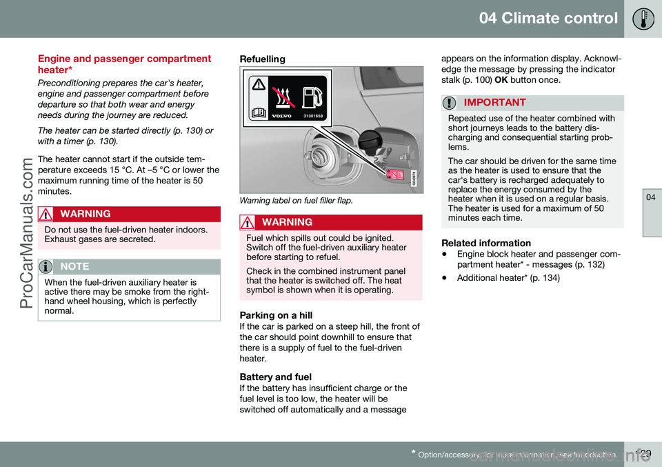
Warning label on fuel filler flap.
WARNING
Fuel which spills out could be ignited. Switch off the fuel-driven auxiliary heaterbefore starting to refuel. Check in the combined instrument panel that the heater is switched off. The heatsymbol is shown when it is operating.
Parking on a hillIf the car is parked on a steep hill, the front of the car should point downhill to ensure thatthere is a supply of fuel to the fuel-drivenheater.
Battery and fuelIf the battery has insufficient charge or thefuel level is too low, the heater will beswitched off automatically and a message appears on the information display. Acknowl-edge the message by pressing the indicatorstalk (p. 100)
OK button once.
IMPORTANT
Repeated use of the heater combined with short journeys leads to the battery dis-charging and consequential starting prob-lems. The car should be driven for the same time as the heater is used to ensure that thecar's battery is recharged adequately toreplace the energy consumed by theheater when it is used on a regular basis.The heater is used for a maximum of 50minutes each time.
Related information
• Engine block heater and passenger com- partment heater* - messages (p. 132)
• Additional heater* (p. 134)
ProCarManuals.co’
Page 140 of 442
||
05 Loading and storage
05
138* Option/accessory, for more information, see Introduction.
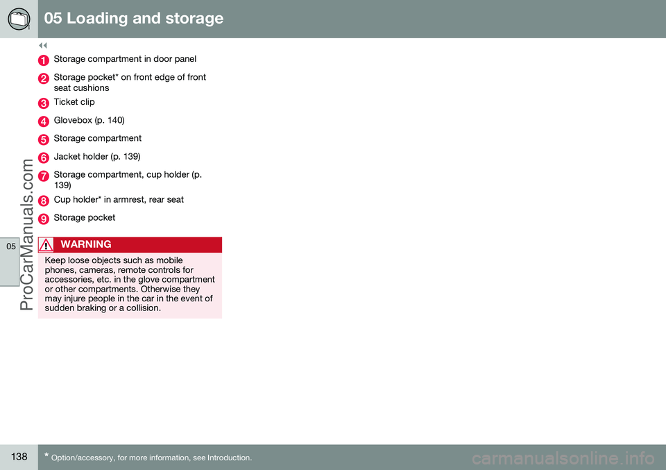
Storage compartment in door panel
Storage pocket* on front edge of front seat cushions
Ticket clip
Glovebox (p. 140)
Storage compartment
Jacket holder (p. 139)
Storage compartment, cup holder (p. 139)
Cup holder* in armrest, rear seat
Storage pocket
WARNING
Keep loose objects such as mobile phones, cameras, remote controls foraccessories, etc. in the glove compartmentor other compartments. Otherwise theymay injure people in the car in the event ofsudden braking or a collision.
ProCarManuals.co’
Page 142 of 442
05 Loading and storage
05
140* Option/accessory, for more information, see Introduction.
Glovebox
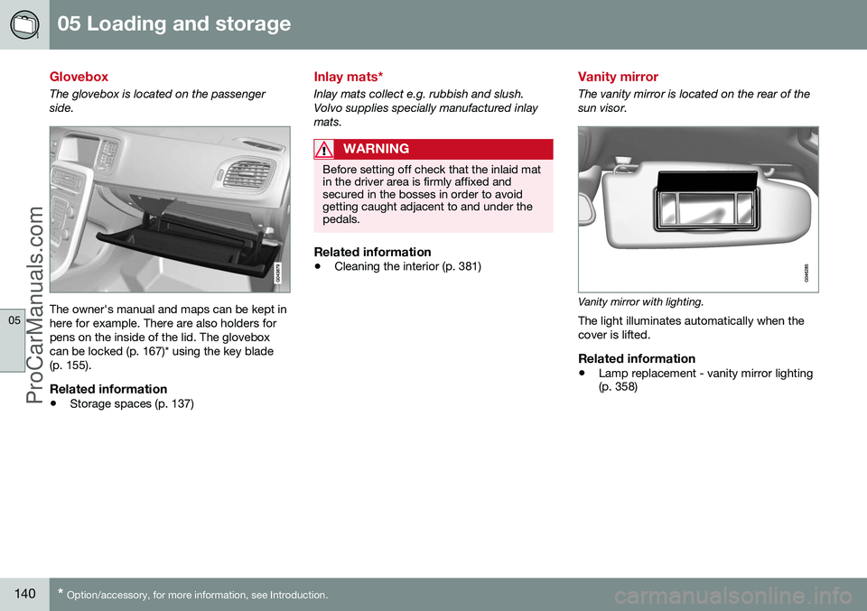
The glovebox is located on the passenger side.
The owner's manual and maps can be kept in here for example. There are also holders forpens on the inside of the lid. The gloveboxcan be locked (p. 167)* using the key blade(p. 155).
Related information
• Storage spaces (p. 137)
Inlay mats*
Inlay mats collect e.g. rubbish and slush. Volvo supplies specially manufactured inlaymats.
WARNING
Before setting off check that the inlaid mat in the driver area is firmly affixed andsecured in the bosses in order to avoidgetting caught adjacent to and under thepedals.
Related information
•Cleaning the interior (p. 381)
Vanity mirror
The vanity mirror is located on the rear of the sun visor.
Vanity mirror with lighting.
The light illuminates automatically when the cover is lifted.
Related information
• Lamp replacement - vanity mirror lighting (p. 358)
ProCarManuals.co’
Page 143 of 442
05 Loading and storage
05
* Option/accessory, for more information, see Introduction.141
Tunnel console - 12 V-sockets
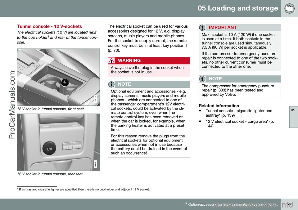
The electrical sockets (12 V) are located next to the cup holder 1
and rear of the tunnel con-
sole.
12 V socket in tunnel console, front seat.
12 V socket in tunnel console, rear seat. The electrical socket can be used for various accessories designed for 12 V, e.g. displayscreens, music players and mobile phones.For the socket to supply current, the remotecontrol key must be in at least key position
I
(p. 70).
WARNING
Always leave the plug in the socket when the socket is not in use.
NOTE
Optional equipment and accessories - e.g. display screens, music players and mobilephones - which are connected to one ofthe passenger compartment's 12V electri-cal sockets, could be activated by the cli-mate control system, even when theremote control key has been removed orwhen the car is locked, for example, whenthe parking heater is activated at a presettime. For this reason remove the plugs from the electrical sockets for optional equipmentor accessories when not in use becausethe battery could be drained in the event ofsuch an occurrence!
IMPORTANT
Max. socket is 10 A (120 W) if one socket is used at a time. If both sockets in thetunnel console are used simultaneously,7.5 A (90 W) per socket is applicable. If the compressor for emergency puncture repair is connected to one of the two sock-ets, no other current consumer must beconnected to the other one.
NOTE
The compressor for emergency puncture repair (p. 333) has been tested andapproved by Volvo.
Related information
• Tunnel console - cigarette lighter and ashtray* (p. 139)
• 12 V electrical socket - cargo area* (p.144)
1
If ashtray and cigarette lighter are specified then there is no cup holder and adjacent 12 V socket.
ProCarManuals.co’
Page 144 of 442
05 Loading and storage
05
142* Option/accessory, for more information, see Introduction.
Loading
Payload depends on the car's kerb weight. Payload depends on the car's kerb weight. The total of the weight of the passengers andall accessories reduces the car's payload bya corresponding weight. For more detailedinformation on weights, see Weights (p. 390).
The tailgate is opened via a buttonon the lighting panel or the remotecontrol key, see Locking/unlocking -
tailgate (p. 167).
WARNING
The car’s driving properties change depending on the weight and positioningof the load.
To bear in mind when loading
• Position the load firmly against the rear seat's backrest.
Note that objects must not prevent the func- tion of the WHIPS system for the front seats ifany of the rear seat's backrests is foldeddown, seeWHIPS - seating position (p. 35).
• Centre the load.
• Heavy objects should be placed as low as possible. Avoid placing heavy loads onlowered backrests.
• Cover sharp edges with something soft toavoid damaging the upholstery. •
Secure all loads to the load retaining eye-lets with straps or web lashings.
WARNING
A loose object weighing 20 kg can, in a frontal collision at a speed of 50 km/h,carry the impact of an item weighing1000 kg.
WARNING
The protection provided by the inflatable curtain in the headlining may be compro-mised or eliminated by high loads.
• Never load cargo above the backrest.
WARNING
Always secure the load. During heavy braking the load may otherwise shift, caus-ing injury to the car's occupants. Cover sharp edges and sharp corners with something soft. Switch off the engine and apply the park- ing brake when loading/unloading longitems. Otherwise you may accidentallyknock the gear lever or gear selector withthe load into a drive position - and the carcould then move off.
Related information
•
Load retaining eyelets (p. 143)
• Safety net* (p. 145) •
Loading - long load (p. 143)
• Roof load (p. 143)
ProCarManuals.co’
Page 145 of 442
05 Loading and storage
05
143
Loading - long load
To simplify loading (p. 142) in the cargo area, the rear seat backrest can be folded down.The passenger seat backrest can also be folded for an extra long load2
.
Lowering the rear seat backrestTo simplify loading in the cargo area, the rear seat backrest can be folded down, see Seats,rear (p. 74).
Roof load
The load carriers recommended for roof loads are the ones developed by Volvo. This is inorder to avoid damage to the car and in orderto achieve the maximum possible safety dur-ing a journey. Carefully follow the installation instructions supplied with the carriers.
• Check periodically that the load carriers and load are properly secured. Lash theload securely with retaining straps.
• Distribute the load evenly over the loadcarriers. Put the heaviest objects at thebottom.
• The size of the area exposed to the wind,and therefore fuel consumption, increasewith the size of the load.
• Drive gently. Avoid quick acceleration,heavy braking and hard cornering.
WARNING
The car's centre of gravity and driving cha- racteristics are altered by roof loads. Forinformation about the maximum allowableload on the roof, including load carriersand any space box, Weights (p. 390).
Related information
•
Loading (p. 142)
Load retaining eyelets
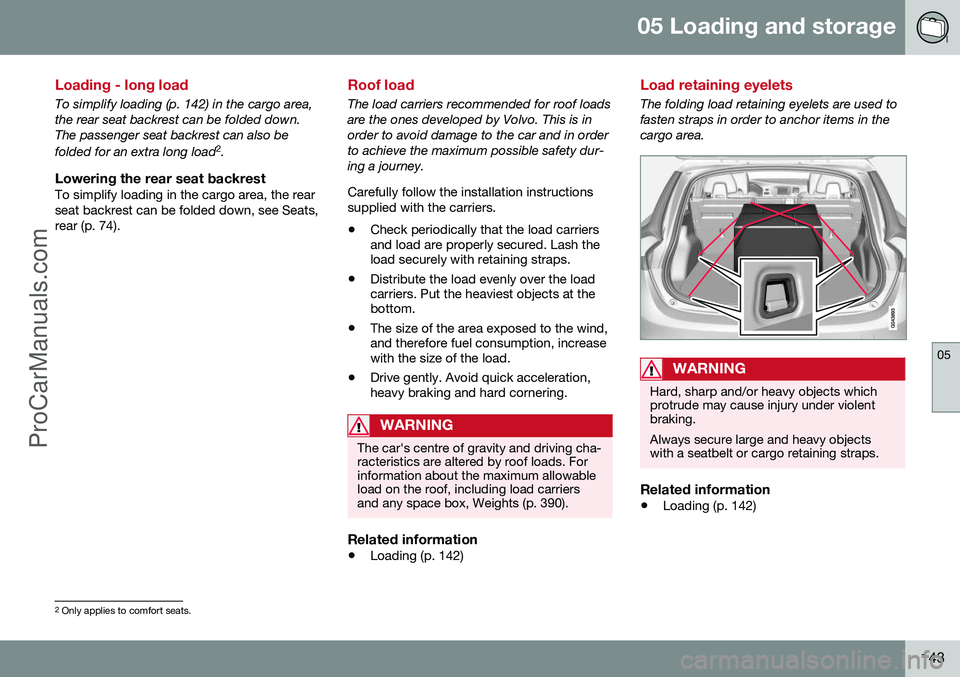
The folding load retaining eyelets are used to fasten straps in order to anchor items in thecargo area.
WARNING
Hard, sharp and/or heavy objects which protrude may cause injury under violentbraking. Always secure large and heavy objects with a seatbelt or cargo retaining straps.
Related information
• Loading (p. 142)
2
Only applies to comfort seats.
ProCarManuals.co’
Page 148 of 442
||
05 Loading and storage
05
146* Option/accessory, for more information, see Introduction.
Removing the net cassettes1. Roll the safety nets into the cassettes in
accordance with the procedure in the section entitled "Using the safety net",but in reverse.
2. Fold the whole backrest forward.
3. Slide the cassettes out until they loosen from the anchor rails.
Store the cassettes in their compartment under the cargo area floor hatch.
WARNING
Loads in the luggage compartment must be anchored well, and also using a cor-rectly fitted safety net.
Related information
• Loading (p. 142)
• Safety grille (p. 146)
Safety net* combined with cargo cover
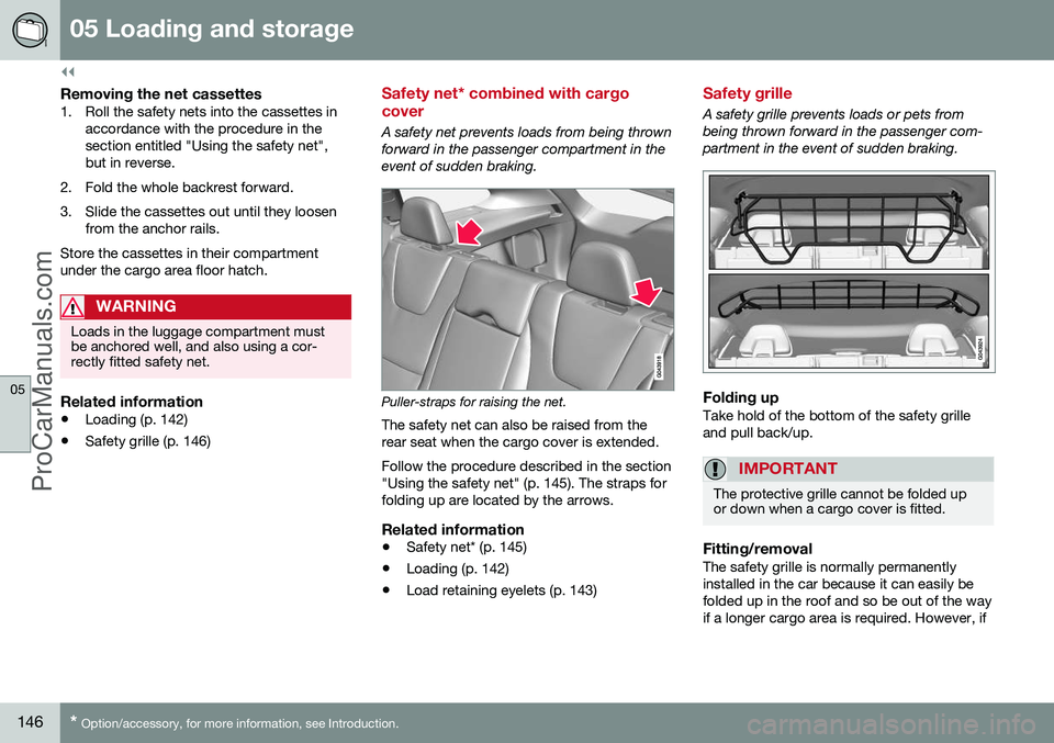
A safety net prevents loads from being thrown
forward in the passenger compartment in the event of sudden braking.
Puller-straps for raising the net.
The safety net can also be raised from the rear seat when the cargo cover is extended. Follow the procedure described in the section "Using the safety net" (p. 145). The straps forfolding up are located by the arrows.
Related information
• Safety net* (p. 145)
• Loading (p. 142)
• Load retaining eyelets (p. 143)
Safety grille
A safety grille prevents loads or pets from being thrown forward in the passenger com-partment in the event of sudden braking.
Folding upTake hold of the bottom of the safety grille and pull back/up.
IMPORTANT
The protective grille cannot be folded up or down when a cargo cover is fitted.
Fitting/removalThe safety grille is normally permanently installed in the car because it can easily befolded up in the roof and so be out of the wayif a longer cargo area is required. However, if
ProCarManuals.co’
Page 151 of 442
06 Locks and alarm
06
* Option/accessory, for more information, see Introduction.149
Remote control key with key blade
The remote control key is used to start the car and for locking and unlocking. It contains adetachable key blade (p. 155) made of metal.The visible section is available in two versionsso that it is possible to distinguish betweenthe remote control keys. The car is supplied with 2 remote control keys or PCCs* (Personal Car Communicator). Additional remote control keys can be ordered - up to 6 can be programmed andused for the same car.
WARNING
If there are children in the car: Remember to switch off the supply to the power windows and sunroof by removingthe remote control key if the driver leavesthe car.
Remote control key with PCC (p. 153) has increased functionality compared with theremote control key, see PCC* - unique func-tions (p. 153).
Related information
• Remote control key - functions (p. 151)
Remote control key - losing
If you lose a remote control key then a new one can be ordered at a workshop - anauthorised Volvo workshop is recommended. The remaining remote control keys must be taken to the Volvo workshop. The code of themissing remote control key must be erasedfrom the system as a theft prevention meas-ure. The current number of keys registered tothe car can be checked in the menu systemMY CAR
. For a description of the menu sys-
tem, see MY CAR (p. 103).
Related information
• Remote control key - functions (p. 151)
Key memory*
The key memory in the remote control key (p. 149) means that certain settings in the car canbe individually adapted for different people. The key memory function is available in com- bination with power seat and power rearviewand door mirrors. Settings for door mirrors,driver's seat and steering force can be savedin the key memory.
Key memory – door mirrors and driver's
seat
The settings are automatically connected toeach respective remote control key, see Keymemory* in remote control key (p. 74) andAdjustable steering force* (p. 257). Afterlocking with the remote control key the set-ting of the combined instrument panel'stheme is also saved in the key, see MY CAR(p. 103). The function can be activated/deactivated in the menu system MY CAR. For a description
of the menu system, see MY CAR (p. 103). For cars with the Keyless drive function, see Keyless drive* (p. 159).
ProCarManuals.co’