VOLVO V90 2017 Owners Manual
Manufacturer: VOLVO, Model Year: 2017, Model line: V90, Model: VOLVO V90 2017Pages: 594, PDF Size: 15.07 MB
Page 491 of 594
WHEELS AND TYRES
* Option/accessory.489
Calibrating tyre monitoring *
In order for the Indirect Tyre Pressure Monitoring System (ITPMS) to work correctly, a referencevalue for the tyre pressure must be determined.This must be performed each time the tyres arechanged or the tyre pressure is changed.
For example, when driving with a heavy load or at high speed above 160 km/h (100 mph), the tyrepressure should be adjusted in accordance withVolvo's recommended tyre pressure values. Fol-lowing which, the system must be recalibrated.
1. Stop the engine.
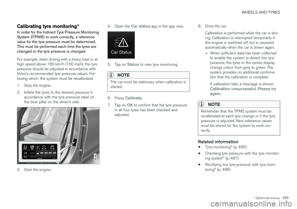
2. Inflate the tyres to the desired pressure in accordance with the tyre pressure label on the door pillar on the driver's side.
3. Start the engine. 4.
Open the
Car status app in the app view.
5.Tap on Status to view tyre monitoring.
NOTE
The car must be stationary when calibration is started.
6.Press Calibrate.
7. Tap on
OK to confirm that the tyre pressure
in all four tyres has been checked and adjusted. 8. Drive the car.
Calibration is performed while the car is driv-ing. Calibration is interrupted temporarily ifthe engine is switched off, but is resumedautomatically when the car is driven again.
> When sufficient data has been collectedto enable the system to detect low tyre pressure, the tyres in the centre displaychange colour from grey to green. Thesystem provides no additional confirma-tion that the calibration is complete. If calibration fails, a message is shown:
Calibration unsuccessful. Please try again..
NOTE
Remember that the TPMS system must be recalibrated at each tyre change or if the tyrepressure is adjusted. New reference valuesmust be stored for the system to work cor-rectly.
Related information
• Tyre monitoring
* (p. 485)
• Checking tyre pressure with the tyre monitor- ing system
* (p. 487)
• Rectifying low tyre pressure with tyre moni-toring
* (p. 488)
Page 492 of 594
WHEELS AND TYRES
490
Emergency puncture repair kitThe emergency puncture repair kit, Temporary Mobility Kit (TMK), is used to seal a puncture aswell as to check and adjust the air pressure.
The puncture repair kit consists of a compressor and a bottle with sealing fluid. The sealing worksas a temporary repair. The sealing fluid effectivelyseals tyres punctured in the tread. The puncture repair kit has limited capacity to seal tyres which have punctures in the wall. Donot use the puncture repair kit on tyres that havelarger slits, cracks or similar damage.
NOTE
The emergency puncture repair kit is only intended for sealing tyres with a puncture inthe tread.
NOTE
The compressor for temporary emergency puncture repair has been tested andapproved by Volvo.
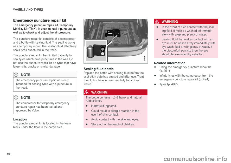
LocationThe puncture repair kit is located in the foam block under the floor in the cargo area.
Sealing fluid bottleReplace the bottle with sealing fluid before the expiration date has passed and after use. Treatthe old bottle as environmentally hazardouswaste.
WARNING
The bottle contains 1.2-Ethanol and natural rubber-latex.
• Harmful if ingested.
• Could result in allergic reaction in the event of skin contact.
• Avoid contact with the skin and eyes.
• Store out of the reach of children.
WARNING
• In the event of skin contact with the seal- ing fluid, it must be washed off immedi-ately with soap and plenty of water.
• Sealing fluid that makes contact with aneye must be rinsed away immediately witheye wash fluid or with plenty of water. Ifthe discomfort persists then the eyeshould be examined by a doctor.
Related information
• Using the emergency puncture repair kit(p. 491)
• Inflate tyres with the compressor from theemergency puncture repair kit (p. 494)
• Tyres (p. 482)
Page 493 of 594
WHEELS AND TYRES
}}
491
Using the emergency puncture repair kit Seal a puncture with the emergency puncture repair kit, Temporary Mobility Kit (TMK).
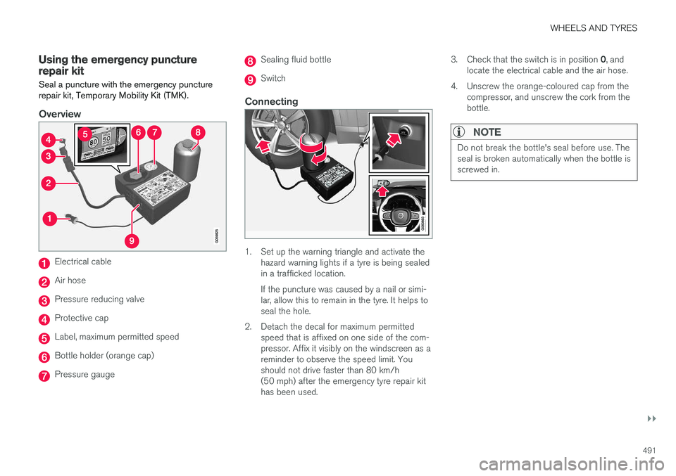
Overview
Electrical cable
Air hose
Pressure reducing valve
Protective cap
Label, maximum permitted speed
Bottle holder (orange cap)
Pressure gauge
Sealing fluid bottle
Switch
Connecting
1. Set up the warning triangle and activate thehazard warning lights if a tyre is being sealed in a trafficked location. If the puncture was caused by a nail or simi- lar, allow this to remain in the tyre. It helps toseal the hole.
2. Detach the decal for maximum permitted speed that is affixed on one side of the com-pressor. Affix it visibly on the windscreen as areminder to observe the speed limit. Youshould not drive faster than 80 km/h(50 mph) after the emergency tyre repair kithas been used. 3.
Check that the switch is in position 0, and
locate the electrical cable and the air hose.
4. Unscrew the orange-coloured cap from the compressor, and unscrew the cork from thebottle.
NOTE
Do not break the bottle's seal before use. The seal is broken automatically when the bottle isscrewed in.
Page 494 of 594
||
WHEELS AND TYRES
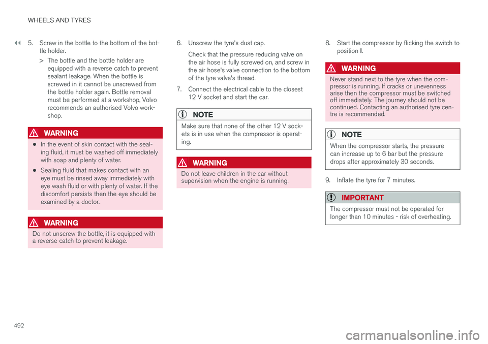
4925. Screw in the bottle to the bottom of the bot-
tle holder.
> The bottle and the bottle holder areequipped with a reverse catch to prevent sealant leakage. When the bottle isscrewed in it cannot be unscrewed fromthe bottle holder again. Bottle removalmust be performed at a workshop, Volvorecommends an authorised Volvo work-shop.
WARNING
•In the event of skin contact with the seal- ing fluid, it must be washed off immediatelywith soap and plenty of water.
• Sealing fluid that makes contact with aneye must be rinsed away immediately witheye wash fluid or with plenty of water. If thediscomfort persists then the eye should beexamined by a doctor.
WARNING
Do not unscrew the bottle, it is equipped with a reverse catch to prevent leakage. 6. Unscrew the tyre's dust cap.
Check that the pressure reducing valve on the air hose is fully screwed on, and screw inthe air hose's valve connection to the bottomof the tyre valve's thread.
7. Connect the electrical cable to the closest 12 V socket and start the car.
NOTE
Make sure that none of the other 12 V sock- ets is in use when the compressor is operat-ing.
WARNING
Do not leave children in the car without supervision when the engine is running. 8. Start the compressor by flicking the switch to
position I.
WARNING
Never stand next to the tyre when the com- pressor is running. If cracks or unevennessarise then the compressor must be switchedoff immediately. The journey should not becontinued. Contacting an authorised tyre cen-tre is recommended.
NOTE
When the compressor starts, the pressure can increase up to 6 bar but the pressuredrops after approximately 30 seconds.
9. Inflate the tyre for 7 minutes.
IMPORTANT
The compressor must not be operated for longer than 10 minutes - risk of overheating.
Page 495 of 594
WHEELS AND TYRES
}}
493
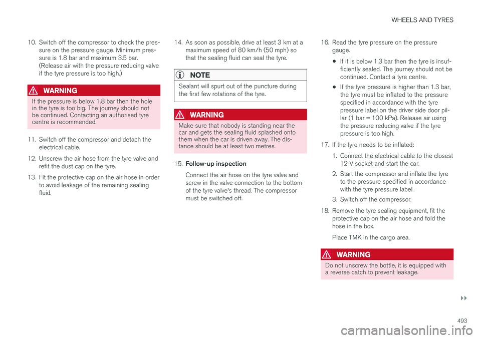
10. Switch off the compressor to check the pres-
sure on the pressure gauge. Minimum pres- sure is 1.8 bar and maximum 3.5 bar.(Release air with the pressure reducing valveif the tyre pressure is too high.)
WARNING
If the pressure is below 1.8 bar then the hole in the tyre is too big. The journey should notbe continued. Contacting an authorised tyrecentre is recommended.
11. Switch off the compressor and detach the electrical cable.
12. Unscrew the air hose from the tyre valve and refit the dust cap on the tyre.
13. Fit the protective cap on the air hose in order to avoid leakage of the remaining sealing fluid. 14. As soon as possible, drive at least 3 km at a
maximum speed of 80 km/h (50 mph) sothat the sealing fluid can seal the tyre.
NOTE
Sealant will spurt out of the puncture during the first few rotations of the tyre.
WARNING
Make sure that nobody is standing near the car and gets the sealing fluid splashed ontothem when the car is driven away. The dis-tance should be at least two metres.
15. Follow-up inspection Connect the air hose on the tyre valve and screw in the valve connection to the bottomof the tyre valve's thread. The compressormust be switched off. 16. Read the tyre pressure on the pressure
gauge.
• If it is below 1.3 bar then the tyre is insuf-ficiently sealed. The journey should not becontinued. Contact a tyre centre.
• If the tyre pressure is higher than 1.3 bar,the tyre must be inflated to the pressurespecified in accordance with the tyrepressure label on the driver side door pil-lar (1 bar = 100 kPa). Release air usingthe pressure reducing valve if the tyrepressure is too high.
17. If the tyre needs to be inflated: 1. Connect the electrical cable to the closest12 V socket and start the car.
2. Start the compressor and inflate the tyre to the pressure specified in accordancewith the tyre pressure label.
3. Switch off the compressor.
18. Remove the tyre sealing equipment, fit the protective cap on the air hose and fold thehose in the box. Place TMK in the cargo area.
WARNING
Do not unscrew the bottle, it is equipped with a reverse catch to prevent leakage.
Page 496 of 594
||
WHEELS AND TYRES
49419. Refit the dust cap on the tyre.
NOTE
•
After a tyre has been inflated, always refit the dust cap in order to avoid damage tothe valve from gravel, dirt, etc.
• Only use plastic dust caps. Metal dustcaps can rust and become difficult tounscrew.
NOTE
The sealing fluid bottle and the hose must be replaced after use. Volvo recommends thatthis replacement is performed by an author-ised Volvo workshop.
WARNING
Check the tyre pressure regularly.
Volvo recommends that the car is driven to the nearest authorised Volvo workshop for thereplacement/repair of the damaged tyre. Advisethe workshop that the tyre contains sealing fluid.
WARNING
You should not drive faster than 80 km/h (50 mph) after the emergency tyre repair kithas been used. Volvo recommends a visit toan authorised Volvo workshop for inspectionof the sealed tyre (maximum driving distanceis 200 km). The staff there can determinewhether or not the tyre can be repaired or if itneeds to be replaced.
Related information
• Emergency puncture repair kit (p. 490)
Inflate tyres with the compressor from the emergency puncture repairkit The car's original tyres can be inflated using the compressor in the emergency puncture repairkit.
1. The compressor must be switched off. Make
sure that the switch is in position 0 and
locate the cable and air hose.
2. Unscrew the wheel's dust cap and screw in the air hose valve connection to the bottom of the thread on the tyre's air valve.
3. Connect the cable to one of the car's 12 V sockets and start the engine.
WARNING
Inhaling car exhaust fumes could result in danger to life. Never leave the engine runningin sealed areas or areas that lack sufficientventilation.
WARNING
Do not leave children in the car without supervision when the engine is running.
4. Start the compressor by flicking the switch to position I.
Page 497 of 594
WHEELS AND TYRES
}}
* Option/accessory.495
IMPORTANT
Risk of overheating. The compressor must not run for more than 10 minutes.
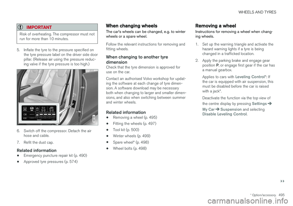
5. Inflate the tyre to the pressure specified on
the tyre pressure label on the driver side door pillar. (Release air using the pressure reduc-ing valve if the tyre pressure is too high.)
6. Switch off the compressor. Detach the airhose and cable.
7. Refit the dust cap.
Related information
• Emergency puncture repair kit (p. 490)
• Approved tyre pressures (p. 574)
When changing wheels
The car's wheels can be changed, e.g. to winter wheels or a spare wheel.
Follow the relevant instructions for removing and fitting wheels.
When changing to another tyre
dimension
Check that the tyre dimension is approved foruse on the car. Contact an authorised Volvo workshop for updat- ing the software at each change of tyre dimen-sion. A software download may be necessaryboth when changing to larger and smaller dimen-sions, and also when switching between summerand winter wheels.
Related information
• Removing a wheel (p. 495)
• Fitting the wheels (p. 497)
• Tool kit (p. 500)
• Winter wheels (p. 499)
• Spare wheel
* (p. 498)
• Wheel bolts (p. 498)
Removing a wheel
Instructions for removing a wheel when chang- ing wheels.
1. Set up the warning triangle and activate the hazard warning lights if a tyre is being changed in a trafficked location.
2. Apply the parking brake and engage gear position P, or engage first gear if the car has
a manual gearbox. Applies to cars with
Leveling Control* : If
the car is equipped with air suspension, this must be disabled before the car is raised with a jack *.
Deactivate the function via the top view of the centre display by pressing
Settings
My CarSuspension and selectingDisable Leveling Control.
Page 498 of 594
||
WHEELS AND TYRES
* Option/accessory.
496
WARNING
Check that the jack is not damaged, that the threads are thoroughly lubricated and that it isfree from dirt.
3. Take out the jack *, wheel wrench * and tools
for the wheel bolts' plastic caps that are fitted in the foam block.
Tool for removing the plastic caps on the wheel bolts.
NOTE
The normal car jack is only designed for occa- sional, short-term use, such as when chang-ing a wheel after a puncture, changing to win-ter/summer wheels, etc. Only the jack for thespecific car model may be used to raise thecar. If the car is to be jacked up more often, orfor a longer time than is required just tochange a wheel, use of a garage jack is rec-ommended. In this instance, follow theinstructions for use that come with the equip-ment.
4. Place chocks in front of and behind the wheels which will remain on the ground to prevent them from rolling. Use heavy woodenblocks or large stones for example.
5. Screw together the towing eye with the wheel wrench * to the stop position.
IMPORTANT
The towing eye must be screwed all the way into the wheel bolt wrench.
6. Remove the plastic caps from the wheel
bolts with the intended tool.
7. Loosen the wheel bolts ½-1 turn anticlock- wise with the wheel wrench *.
WARNING
Never position anything between the ground and the jack, nor between the jack and thecar's jacking point.
IMPORTANT
The ground must be firm, smooth and level.
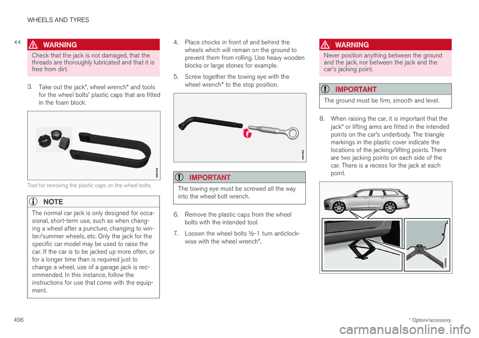
8. When raising the car, it is important that the
jack* or lifting arms are fitted in the intended
points on the car's underbody. The triangle markings in the plastic cover indicate thelocations of the jacking/lifting points. Thereare two jacking points on each side of thecar. There is a recess for the jack at eachpoint.
Page 499 of 594
WHEELS AND TYRES
* Option/accessory.497
Crank up the jack
* so that it makes contact
with the car's jacking point. Check that the head of the jack is correctly positioned in thejacking point so that the bump in the centreof the head fits into the jacking point holeand the base is positioned vertically belowthe jacking point. Also make sure you turnthe jack so that the crank is as far away fromthe side of the car as possible, at which pointthe jack's arms are perpendicular to thedirection of the car.
WARNING
Never crawl under the car when it is raised on the jack. Passengers must leave the car when it is raised on the jack. If a wheel must bechanged in a trafficked environment, passen-gers must stand in a safe place.
9. Lift the car so that the wheel is free. Remove the wheel bolts and lift off the wheel.
Related information
• When changing wheels (p. 495)
• Raise the car (p. 512)
• Fitting the wheels (p. 497)
• Tool kit (p. 500)
Fitting the wheels Instructions for fitting a wheel when changing wheels.
WARNING
Never crawl under the car when it is raised on the jack. Passengers must leave the car when it is raised on the jack. If a wheel must bechanged in a trafficked environment, passen-gers must stand in a safe place.
1. Clean the contact surfaces between wheel and hub.
2. Put on the wheel. Tighten the wheel bolts thoroughly. Do not use lubricant on the threads of the
wheel bolts.
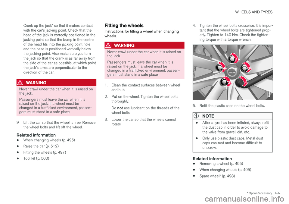
3. Lower the car so that the wheels cannot rotate. 4. Tighten the wheel bolts crosswise. It is impor-
tant that the wheel bolts are tightened prop- erly. Tighten to 140 Nm. Check the tighten-ing torque with a torque wrench.
5. Refit the plastic caps on the wheel bolts.
NOTE
• After a tyre has been inflated, always refit the dust cap in order to avoid damage tothe valve from gravel, dirt, etc.
• Only use plastic dust caps. Metal dustcaps can rust and become difficult tounscrew.
Related information
•Removing a wheel (p. 495)
• When changing wheels (p. 495)
• Spare wheel
* (p. 498)
Page 500 of 594
WHEELS AND TYRES
* Option/accessory.
498
Wheel bolts
Wheel bolts are used to attach the wheels to the hubs.
IMPORTANT
The wheel bolts must be tightened to 140 Nm. Overtightening or loose tightening maydamage the nuts and the bolts.
Only use rims that are tested and approved by Volvo and which are Volvo genuine accessories. Check the tightening torque of the wheel bolts with a torque wrench. Do not use lubricant on the threads of the wheel
bolts.
Locking wheel bolts *In the foam block under the cargo area floor there is space for the sleeve for the lockablewheel bolts.
Related information
•When changing wheels (p. 495)
Spare wheel
*
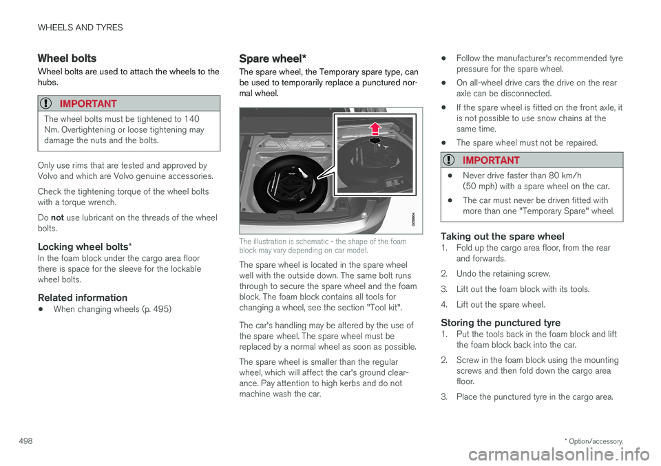
The spare wheel, the Temporary spare type, can be used to temporarily replace a punctured nor-mal wheel.
The illustration is schematic - the shape of the foam block may vary depending on car model.
The spare wheel is located in the spare wheel well with the outside down. The same bolt runsthrough to secure the spare wheel and the foamblock. The foam block contains all tools forchanging a wheel, see the section "Tool kit". The car's handling may be altered by the use of the spare wheel. The spare wheel must bereplaced by a normal wheel as soon as possible. The spare wheel is smaller than the regular wheel, which will affect the car's ground clear-ance. Pay attention to high kerbs and do notmachine wash the car. •
Follow the manufacturer's recommended tyrepressure for the spare wheel.
• On all-wheel drive cars the drive on the rearaxle can be disconnected.
• If the spare wheel is fitted on the front axle, itis not possible to use snow chains at thesame time.
• The spare wheel must not be repaired.
IMPORTANT
• Never drive faster than 80 km/h (50 mph) with a spare wheel on the car.
• The car must never be driven fitted withmore than one "Temporary Spare" wheel.
Taking out the spare wheel1. Fold up the cargo area floor, from the rear
and forwards.
2. Undo the retaining screw.
3. Lift out the foam block with its tools.
4. Lift out the spare wheel.
Storing the punctured tyre1. Put the tools back in the foam block and lift the foam block back into the car.
2. Screw in the foam block using the mounting screws and then fold down the cargo area floor.
3. Place the punctured tyre in the cargo area.