air condition VOLVO V90 2017 Owners Manual
[x] Cancel search | Manufacturer: VOLVO, Model Year: 2017, Model line: V90, Model: VOLVO V90 2017Pages: 594, PDF Size: 15.07 MB
Page 6 of 594

4
Adapting the beam pattern from the headlamps141
Front fog lamps/cornering lights *
142
Rear fog lamp 142
Brake lights 143
Hazard warning flashers 143
Using direction indicators 144
Passenger compartment lighting 145
Home safe light duration 148
Approach light duration 148
Using windscreen wipers 148
Activating/deactivating the rain sensor 149
Windscreen and headlamp washers 150
Rear window wiper and washer 151
Power windows 151
Operating power windows 152
Using the sun blind *
153
Adjusting the door mirrors 153
Interior rearview mirror 155
Compass *
156
Calibrating the compass *
157
Panorama roof *
158
Operating the panorama roof *
159
HomeLink ®
* 162
Programming HomeLink®
* 163
Trip computer 165
Show trip data in the driver display 166
Show trip statistics in the centre display 168
Settings view 169
Categories in the settings view 170
Changing system settings in the set- tings view 172
Resetting settings in the settings view 173
Driver profiles 174
Selecting driver profile 174
Editing a driver profile 175
Linking remote control key to driverprofile 176
Importing/exporting a driver profilefrom/to USB 177
Changing settings for apps 178
Resetting user data for change ofownership 179
CLIMATE CONTROL
Climate control
182
Climate control - sensors 183
Perceived temperature 183
Air quality 184
Passenger compartment filter 185
Clean Zone Interior Package *
185
Interior Air Quality System *
185
Climate controls 186
Climate controls in the centre display 187
Climate controls at the rear of the tunnel console * 188
Auto-regulating the climate 189
Activating/deactivating air conditioning 190
Regulating the temperature 190
Regulating the fan level 193
Activating/deactivating defrost of windows and door mirrors 194
Activating/deactivating air recirculation 196
Air distribution 197
Changing the air distribution 198
Opening/closing and aiming the air vents 199
Table of air distribution options 201
Activating/deactivating heating of the seats * 203
Activating/deactivating ventilation ofthe seats * 204
Page 13 of 594

11
Wiper blades in service position527
Replacing a wiper blade 528
Filling washer fluid 529
Starter battery 530
Symbols on the batteries 533
Support battery 533
Fuses 535
Replacing a fuse 536
Fuses in engine compartment 537
Fuses under glovebox 542
Fuses in cargo area 546
Cleaning the exterior 549
Polishing and waxing 551
Rustproofing 552
Cleaning the interior 552
Cleaning the centre display 553
Paint damage 554
Repairing paint damage 555
SPECIFICATIONS
Type designations558
Dimensions 561
Weights 563
Towing capacity and towball load 564
Engine specifications 566
Engine oil — specifications 567
Adverse driving conditions for engine oil 569
Coolant — specifications 570
Transmission fluid — specifications 570
Brake fluid — specifications 570
Fuel tank - volume 571
Air conditioning — specifications 571
Fuel consumption and CO2 emissions 572
Approved tyre pressures 574
Performance 575
ALPHABETICAL INDEX
Alphabetical Index 577
Page 24 of 594

INTRODUCTION
22
Recording data As part of Volvo's safety and quality assurance, certain information about the vehicle's operation,functionality and incidents are recorded in thecar.
This vehicle is equipped with an "Event Data Recorder" (EDR). Its primary purpose is to regis-ter and record data related to traffic accidents orcollision-like situations, such as times when theairbag deploys or the vehicle strikes an obstaclein the road. The data is recorded in order toincrease understanding of how vehicle systemswork in these types of situations. The EDR isdesigned to record data related to vehicledynamics and safety systems for a short time,usually 30 seconds or less. The EDR in this vehicle is designed to record data related to the following in the event of trafficaccidents or collision-like situations: •How the various systems in the car worked
• Whether the driver and passenger seatbelts were fastened/tensioned
• The driver's use of the accelerator or brakepedal
• The travel speed of the vehicle
This information can help us better understandthe circumstances in which traffic accidents, inju-ries and damage occur. The EDR only recordsdata when a non-trivial collision situation occurs.The EDR does not record any data during normal driving conditions. Similarly, the system neverregisters who is driving the vehicle or the geo-graphic location of the accident or near-miss sit-uation. However, other parties, such as the police,could use the recorded data in combination withthe type of personally identifiable informationroutinely collected after a traffic accident. Specialequipment and access to either the vehicle or theEDR is required to be able to interpret the regis-tered data. In addition to the EDR, the car is equipped with a number of computers designed to continuallycheck and monitor the function of the car. Theycan record data during normal driving conditions,but in particular register faults affecting the vehi-cle's operation and functionality, or upon activa-tion of the vehicle's driver support function (e.g.City Safety and the auto brake function). Some of the recorded data is required to enable service and maintenance technicians to diagnoseand remedy any faults that occurred in the vehi-cle. The registered information is also needed toenable Volvo to satisfy legal requirements laid outin laws and by government authorities. Informa-tion registered in the vehicle is stored in its com-puter until the vehicle is serviced or repaired. In addition to the above, the registered informa- tion can be used in aggregate form for researchand product development with the aim of contin-uously improving the safety and quality of Volvocars.
Volvo will not contribute to the above-describedinformation being disclosed to third parties with-out the vehicle owner's consent. To comply withnational legislation and regulations, Volvo may beforced to disclose information of this nature tothe police or other authorities who may assert alegal right to access such. Special technicalequipment which Volvo and workshops that haveentered into agreements with Volvo have accessto is required to be able to read and interpret therecorded data. Volvo is responsible that the infor-mation, which is transferred to Volvo during serv-icing and maintenance, is securely stored andmanaged and that its management complies withrelevant legal requirements. For further informa-tion - contact a Volvo dealer.
Page 28 of 594

||
INTRODUCTION
* Option/accessory.
26
Contributing to a better environment
An energy-efficient and fuel-efficient car not only contributes to a reduced impact on the environ-ment, but also means reduced costs for theowner of the car. As the driver, it is easy toreduce fuel consumption and thereby savemoney and contribute to a better environment -here is some advice:
• Plan for an effective average speed. Speedsabove approx. 80 km/h (approx. 50 mph)and below 50 km/h (approx. 30 mph) lead toincreased energy consumption.
• Follow the Service and Warranty Booklet'srecommended intervals for service and main-tenance of the car.
• Avoid letting the engine idle - switch off theengine when stationary for longer periods.Pay attention to local regulations.
• Plan the journey - a lot of unnecessary stopsand uneven speed contribute to increasedfuel consumption.
• Use preconditioning
* before starting in cold
conditions - it improves starting capacity andreduces wear in cold weather. The enginereaches normal operating temperature morequickly, which decreases consumption andreduces emissions.
Also remember to always dispose of environmen-tally hazardous waste, such as batteries and oil, inan environmentally safe manner. Consult a work-shop in the event of uncertainty about how this type of waste should be discarded - an author-ised Volvo workshop is recommended.
Efficient emission controlYour Volvo is manufactured following the concept"Clean inside and out" – a concept that encom-passes a clean interior environment as well ashighly efficient emission control. In many casesthe exhaust emissions are well below the applica-ble standards.
Clean air in the passenger
compartment
A passenger compartment filter prevents dustand pollen from entering the passenger compart-ment via the air intake. The Interior Air Quality System (IAQS) * ensures
that the incoming air is cleaner than the air in the traffic outside. The system cleans the air in the passenger com- partment from contaminants such as particles,hydrocarbons, nitrous oxides and ground-levelozone. If the outside air is contaminated then theair intake is closed and the air is recirculated.Such a situation may arise in heavy traffic,queues and tunnels for example. IAQS is a part of the Clean Zone Interior Pack- age (CZIP) *, which also includes a function that
allows the fan to start when the car is unlocked with the remote control key.
InteriorThe material used in the interior of a Volvo iscarefully selected and has been tested in order tobe pleasant and comfortable. Some of the detailsare hand-made, such as the seams of the steer-ing wheel that are sewn by hand. The interior ismonitored in order not to emit strong odours orsubstances that cause discomfort in the event ofe.g. high heat and bright light.
Volvo workshops and the environmentRegular maintenance creates the conditions for along service life and low fuel consumption foryour car. In this way you also contribute to acleaner environment. When Volvo's workshopsare entrusted with the service and maintenanceof your car it becomes part of Volvo's system.Volvo makes clear demands regarding the way inwhich workshop premises shall be designed inorder to prevent spills and discharges into theenvironment. The workshop staff have the knowl-edge and the tools required to guarantee goodenvironmental care.
RecyclingSince Volvo works from a life cycle perspective, itis also important that the car is recycled in anenvironmentally sound manner. Almost all of thecar can be recycled. The last owner of the car istherefore requested to contact a dealer for refer-ral to a certified/approved recycling facility.
Page 73 of 594
SAFETY
}}
* Option/accessory.71
Child safety
Volvo has child safety equipment (child seats, booster cushions and attachment devices)which is designed for fitting in this particular car.
Using Volvo's child safety equipment, the opti- mum conditions are obtained for the child totravel safely in the car. In addition, the child safetyequipment fits well and is simple to use. Children of all ages and sizes must always sit correctly secured in the car. Never allow a child tosit on the knee of a passenger. Volvo recommends that children travel in rear- facing child seats until as late an age as possible,at least up to 3-4 years of age, and then in front-facing booster cushions/child seats until thechild is 140 cm tall.
NOTE
Legal provisions about the type of child seat that must be used for children of differentages and heights vary from country to coun-try. Check what does apply.
NOTE
In the event of questions when fitting child safety products, contact the manufacturer forclearer instructions.
Related information
• Safety (p. 56)
• Child seats (p. 71)
• Integrated booster cushion
* (p. 82)
Child seats
The position of a child in the car and the choice of equipment are dictated by the child's weightand size.
Children should sit comfortably and safely. Make sure that the child seat is being used correctly. Look in the installation instructions for the child seat for the correct fitting.
NOTE
When using child safety products it is impor- tant to read the installation instructionsincluded.
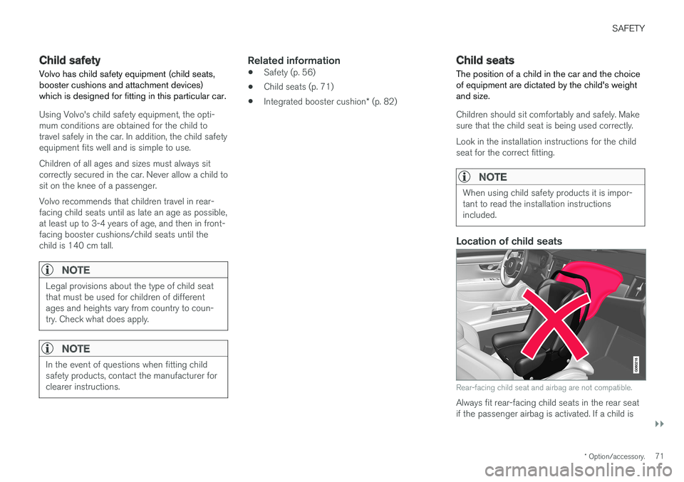
Location of child seats
Rear-facing child seat and airbag are not compatible.
Always fit rear-facing child seats in the rear seat if the passenger airbag is activated. If a child is
Page 98 of 594

||
INSTRUMENTS AND CONTROLS
96
SymbolSpecification
Main beam On The symbol illuminates when main beam is on and with main beamflash.
Active main beam on The symbol lights up blue when active main beam is on. Positionlamps are switched on.
Active main beam off The symbol lights up white when active main beam is off. Positionlamps are switched on.
Main beam On The symbol lights up when main beam and the position lamps areswitched on.
Front fog lamps on This symbol illuminates when the front fog lamp is switched on.
Rear fog lamp on This symbol illuminates when the rear fog lamp is switched on.
SymbolSpecification
Rain sensor on This symbol illuminates when the rain sensor is on.
Preconditioning on The symbol illuminates when the engine block and passenger com-partment heater/air conditioningare preconditioning the car.
Stability system A flashing symbol indicates that the stability system is operating. Ifthe symbol illuminates with con-stant glow then there is a fault inthe system.
Stability system, sport mode The symbol illuminates when the sport mode is activated. Sportmode allows for a more active driv-ing experience. The system thendetects whether the acceleratorpedal, steering wheel movementsand cornering are more active thanin normal driving and then allowscontrolled skidding of the rear sec-tion up to a certain level before itintervenes and stabilises the car.
Symbol Specification
Lane assistance White symbol: Lane assistance is on and road lines are detected. Grey symbol: Lane assistance is on but road lines are not detected. Yellow symbol: Lane assistance warns/intervenes.
Lane assistance and rain sensor White symbol: Lane assistance is on and road lines are detected.Rain sensor is on. Grey symbol: Lane assistance is on but road lines are not detected.Rain sensor is on.
Reminder for doors, bonnet, tailgate and fuel filler flap
If the bonnet, tailgate, fuel filler flap or door is not closed properly then the information or warningsymbol and graphics illuminate in the driver dis-play.
Related information
•Driver display (p. 90)
• Warning symbols in the driver display(p. 97)
• Door and seatbelt reminder (p. 62)
Page 99 of 594

INSTRUMENTS AND CONTROLS
}}
97
Warning symbols in the driver display The warning symbols alert the driver that an important function is activated or that a seriousfault or condition exists.
WARNING
If the brake fluid is below the MIN level in the
brake fluid reservoir, do not drive further before topping up the brake fluid. The loss of brake fluid must be investigated by a workshop. Volvo recommends contactingan authorised Volvo workshop.
WARNING
If the BRAKE and ABS symbols are lit at the same time, there is a risk that the rear end willskid during heavy braking.
Symbol Specification
Warning The red warning symbol illuminates when a fault has been indicatedwhich could affect the safetyand/or driveability of the car. Anexplanatory text is shown on thedriver display at the same time. Thewarning symbol can also illuminatein conjunction with other symbols.
Seatbelt reminder This symbol flashes if someone in a front seat has not put on theirseatbelt or if someone in a rearseat has taken off their seatbelt.
Airbags If the symbol remains illuminated or illuminates while driving, a fault hasbeen detected in one of the car'ssafety systems. Read the messagein the driver display. Volvo recom-mends that an authorised Volvoworkshop is contacted.
Symbol Specification
Fault in brake system If this symbol illuminates, the brake fluid level may be too low. Visit thenearest authorised workshop tohave the brake fluid level checkedand rectified.
Parking brake applied This symbol illuminates with a con- stant glow when the parking brakeis applied. A flashing symbol means that a fault has arisen. Read the messagein the driver display.
Page 114 of 594

INSTRUMENTS AND CONTROLS
* Option/accessory.
112
Head-up display *
The head-up display supplements the car's driver display and projects information from thedriver display onto the windscreen. The projec-ted image can only be seen from the driver posi-tion.
Incoming phone calls.
The head-up display shows warnings and infor- mation relating to speed, cruise control functions,navigation, etc. in the driver's field of vision. Roadsign information and incoming phone calls arealso shown in the head-up display.
IMPORTANT
The display unit from which the information is projected is located in the instrument panel.To avoid damage to the display unit's coverglass - do not store any objects on the coverglass and make sure that no objects fall downonto it.
Examples of what can be shown in the display.
Speed
Cruise control
Navigation
Road signs
A number of symbols can be shown temporarily in the head-up display, e.g.: If the warning symbol illuminates - readthe warning message in the driver dis-play.
If the information symbol illuminates - read the message in the driver display.
NOTE
The driver's ability to see the information in the head-up display is impaired by the follow-ing:
• use of polarising sunglasses
• a driving position which means that thedriver is not sitting centred in the seat
• objects on the display unit's cover glass
• unfavourable light conditions.
NOTE
Certain visual defects may cause headaches and a feeling of stress during the use of thehead-up display.
Page 121 of 594

INSTRUMENTS AND CONTROLS
* Option/accessory.119
Voice recognition control of climate control13
Voice recognition commands for the climate control system to e.g. change temperature, acti-vate a heated seat or change fan level.
Press and say one of the following com-
mands:
• "
Climate" - starts a dialogue for climate
control and shows examples of commands.
• "
Set temperature to X degrees" - sets
the desired temperature.
• "
Raise temperature"/"Lower
temperature" - raise/lower the temperature
setting one step.
• "
Sync temperature" - synchronises the
temperature for all climate zones in the car with the temperature set for the driver's side.
• "
Air on feet"/"Air on body" - opens the
desired air flow.
• "
Air on feet off"/"Air on body off" - closes
the desired air flow.
• "
Set fan to max"/"Turn off fan" - changes
the air flow to Max/Off.
• "
Raise fan speed"/"Lower fan speed" -
raises/lowers the fan level one step.
• "
Turn on auto" - activates automatic climate
regulation. •
"
Air condition on"/"Air condition off" -
activates/deactivates the air conditioning.
• "
Recirculation on"/"Recirculation off" -
activates/deactivates the air circulation.
• "
Turn on defroster "/"Turn off defroster"
- activates/deactivates defrosting of windows and door mirrors.
• "
Turn on max defroster"/"Turn max
defroster off" - activates/deactivates the
max defroster.
• "
Turn on electric defroster"/"Turn off
electric defroster" - activates/deactivates
the heated windscreen *.
• "
Turn on rear defroster"/"Turn off rear
defroster" - activates/deactivates the
heated rear window and door mirrors.
• "
Turn steering wheel heat on"/"Turn
steering wheel heat off" - activates/deac-
tivates the heated steering wheel *.
• "
Raise steering wheel heat"/"Lower
steering wheel heat" - raises/lowers the
setting for the heated steering wheel * one
step.
• "
Turn on seat heat"/"Turn off seat heat"
- activates/deactivates the heated seat *.
• "
Raise seat heat"/"Lower seat heat" -
raises/lowers the setting for the heated seat * one step. •
"
Turn on seat ventilation"/"Turn off seat
ventilation" - activates/deactivates the seat
ventilation *.
• "
Raise seat ventilation"/"Lower seat
ventilation" - raises/lowers the setting for
the ventilated seat * one step.
Related information
• Voice recognition (p. 115)
• Using voice recognition (p. 116)
• Settings for voice recognition (p. 117)
• Climate control (p. 182)
13
Applies to certain markets.
Page 159 of 594

INSTRUMENTS AND CONTROLS
* Option/accessory.157
Calibrating the compass *
The earth is divided into 15 magnetic zones. The compass should be calibrated if the car ismoved between several magnetic zones.
Proceed as follows to perform calibration:
1. Stop the car in a large open area free from steel structures and high-voltage power lines.
2. Start the car and switch off all electrical equipment (air conditioning, wipers, etc.) and ensure that all doors are closed.
NOTE
Calibration may fail or not start at all if electri- cal equipment is not switched off.
3. Hold the button on the underside of the rear-view mirror depressed (use a paper clip or similar) for approx. 3 seconds. The number ofthe current magnetic zone is shown.
Magnetic zones.
4. Press the button repeatedly until the
required magnetic zone (1–15) is shown.
See the map of magnetic zones for the com- pass.
5. Wait until the display returns to showing the character
C, or hold the button on the under-
side of the rearview mirror depressed for approx. 6 seconds until the character
C is
shown.
6. Drive slowly in a circle at a speed of no more than 10 km/h (6 mph) until a compass direc- tion is shown in the display, indicating thatcalibration is complete. Then drive a further 2circles to fine-tune calibration. 7.
Cars with heated windscreen *: If the char-
acter
C is shown in the display when the
heated windscreen is activated, perform the calibration in accordance with point 6 abovewith the heated windscreen activated.
8. Repeat the above procedure as necessary.
Related information
• Compass
* (p. 156)