YAMAHA GIGGLE50 2007 Repair Manual
Manufacturer: YAMAHA, Model Year: 2007, Model line: GIGGLE50, Model: YAMAHA GIGGLE50 2007Pages: 72, PDF Size: 1.05 MB
Page 61 of 72

7-3
1
2
3
4
5
6
7
8
9
SCOOTER CARE AND STORAGE
away the paint.
NOTE:
Consult a Yamaha dealer for advice on
what products to use.
EAU36560
StorageShort-term
Always store your scooter in a cool, dry
place and, if necessary, protect it
against dust with a porous cover.
ECA10820
cC● ●● ●
●
Storing the scooter in a poorly
ventilated room or covering it
with a tarp, while it is still wet,
will allow water and humidity to
seep in and cause rust.
● ●● ●
●
To prevent corrosion, avoid
damp cellars, stables (because
of the presence of ammonia) and
areas where strong chemicals
are stored.
Long-term
Before storing your scooter for several
months:
1. Follow all the instructions in the
“Care” section of this chapter.
2. Fill up the fuel tank and add fuel
stabilizer (if available) to prevent the
fuel tank from rusting and the fuel
from deteriorating. Storage
3. Perform the following steps to pro-
tect the cylinder, piston rings, etc.
from corrosion.
a. Remove the spark plug cap and
spark plug.
b. Pour a teaspoonful of engine oil
into the spark plug bore.
c. Install the spark plug cap onto
the spark plug, and then place
the spark plug on the cylinder
head so that the electrodes are
grounded. (This will limit spark-
ing during the next step.)
d. Turn the engine over several
times with the starter. (This will
coat the cylinder wall with oil.)
e. Remove the spark plug cap from
the spark plug, and then install
the spark plug and the spark plug
cap.
EWA10950
wTo prevent damage or injury from
sparking, make sure to ground the
spark plug electrodes while turning
the engine over.
15P-F8199-E0_ch7.pmd2007/06/13, 11:18 3
Page 62 of 72
7-4
1
2
3
4
5
6
7
8
9
SCOOTER CARE AND STORAGE4. Lubricate all control cables and the
pivoting points of all levers and
pedals as well as of the sidestand/
centerstand.
5. Check and, if necessary, correct
the tire air pressure, and then lift
the scooter so that both of its
wheels are off the ground. Alterna-
tively, turn the wheels a little every
month in order to prevent the tires
from becoming degraded in one
spot.
6. Cover the muffler outlet with a plas-
tic bag to prevent moisture from en-
tering it.
7. Remove the battery and fully
charge it. Store it in a cool, dry
place and charge it once a month.
Do not store the battery in an ex-
cessively cold or warm place [less
than 0 °C (30 °F) or more than 30
°C (90 °F)]. For more information
on storing the battery, see page 6-
20.NOTE:
Make any necessary repairs before
storing the scooter.
15P-F8199-E0_ch7.pmd2007/06/13, 11:18 4
Page 63 of 72
8-1
1
2
3
4
5
6
7
8
9
SPECIFICATIONS
Specifications
EAU26320
SPECIFICATIONS
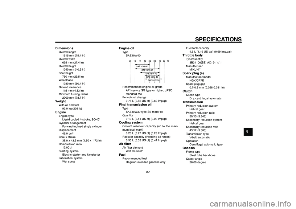
DimensionsOverall length
1915 mm (75.4 in)
Overall width
695 mm (27.4 in)
Overall height
1040 mm (40.9 in)
Seat height
750 mm (29.5 in)
Wheelbase
1280 mm (50.4 in)
Ground clearance
115 mm (4.53 in)
Minimum turning radius
2000 mm (78.7 in)WeightWith oil and fuel
93.0 kg (205 lb)EngineEngine type
Liquid cooled 4-stroke, SOHC
Cylinder arrangement
Forward-inclined single cylinder
Displacement
49.0 cm
3
Bore x stroke
38.0 x 43.6 mm (1.50 x 1.72 in)
Compression ratio
12.00 :1
Starting system
Electric starter and kickstarter
Lubrication system
Wet sump
Engine oilType
SAE10W40
-10 0 10 20 30
40 -20
50
˚C
SAE 10W-30
SAE 10W-40
SAE 15W-40SAE 20W-40SAE 20W-50
Recommended engine oil grade
API service SG type or higher, JASO
standard MA
Periodic oil change
0.78 L (0.82 US qt) (0.69 Imp.qt)Final transmission oilType
SAE10W30 type SE motor oil
Quantity
0.10 L (0.11 US qt) (0.09 Imp.qt)Cooling systemCoolant reservoir capacity (up to the maxi-
mum level mark)
0.26 L (0.27 US qt) (0.23 Imp.qt)
Radiator capacity (including all routes)
0.50 L (0.53 US qt) (0.44 Imp.qt)Air filterAir filter element
Wet element”FuelRecommended fuel
Regular unleaded gasoline onlyFuel tank capacity
4.5 L (1.19 US gal) (0.99 Imp.gal)
Throttle bodyType/quantity
3B31 00(SE AC19-1) / 1
Manufacturer
MIKUNI”Spark plug (s)Manufacturer/model
NGK/CR7E
Spark plug gap
0.7-0.8 mm (0.028-0.031 in)ClutchClutch type
Dry, centrifugal automaticTransmissionPrimary reduction system
Helical gear
Primary reduction ratio
50/13 (3.846)
Secondary reduction system
Helical gear
Secondary reduction ratio
43/12 (3.583)
Transmission type
V-belt automatic
Operation
Centrifugal automatic typeChassisFrame type
Steel tube backbone
Caster angle
26.00 degree
15P-F8199-E0_ch8.pmd2007/07/18, 12:26 1
Page 64 of 72
8-2
1
2
3
4
5
6
7
8
9
SPECIFICATIONSTrail
84.0 mm (3.31 in)Front tireType
Tubeless
Size
120/90-10 57J
Manufacturer/model
CHENG SHIN / C-6022Rear tireType
Tubeless
Size
120/90-10 57J
Manufacturer/model
CHENG SHIN / C-6022
Maximum load
177 kg (390 lb)Tire air pressure (measured on cold
tires)Front
175 kPa (25 psi) (1.75 kgf/cm
2) (1.75 bar)
Rear
175 kPa (25 psi) (1.75 kgf/cm2) (1.75 bar)
Front wheelWheel type
Cast wheel
Rim size
10 x 3.00Rear wheelWheel type
Cast wheel
Rim size
10 x 3.00
Front brakeType
Drum brake
Operation
Right hand operationRear brakeType
Drum brake
Operation
Left hand operationFront suspensionType
Telescopic fork
Spring/shock absorber type
Coil spring
Wheel travel
65.0 mm (2.56 in)Rear suspensionType
Unit swing
Spring/shock absorber type
Coil spring
Wheel travel
56.0 mm (2.20 in)Electrical systemIgnition system
Transistorized coil ignition
Charging system
AC magnetoBatteryModel
GTX5L-BSVoltage, capacity
12 V, 4.0 Ah
HeadlightBulb type
Halogen bulbBulb voltage, wattage x quantityHeadlight
12 V, 35 W/35.0 W x 1
Tail/brake light
12 V, 5.0 W/21.0 W x 1
Front turn signal light
12 V, 10.0 W x 2
Rear turn signal light
12 V, 10.0 W x 2
License plate light (15P3/15P4)
12 V, 5.0 W x 1
Meter lighting
12 V, 1.7 W x 1
High beam indicator light
12 V, 1.7 W x 1
Turn signal indicator light
14 V, 3.0 W x 1
Coolant temperature warning light
12 V, 1.7 W x 1
Engine trouble warning light
12 V, 1.7 W x 1FusesMain fuse
15.0 A
15P-F8199-E0_ch8.pmd2007/07/18, 12:26 2
Page 65 of 72

9-1
1
2
3
4
5
6
7
8
9
CONSUMER INFORMATION
EAU26351
Identification numbersRecord the key identification number,
vehicle identification number and model
label information in the spaces provided
below for assistance when ordering
spare parts from a Yamaha dealer or
for reference in case the vehicle is sto-
len.
KEY IDENTIFICATION NUMBER:
VEHICLE IDENTIFICATION NUMBER:
MODEL LABEL INFORMATION: Identification numbers
Key identification number
Vehicle identification number
EAU26381
Key identification numberZAUM00**
1
1. Key identification numberThe key identification number is
stamped into the key tag.
Record this number in the space pro-
vided and use it for reference when or-
dering a new key.
EAU26342
CONSUMER INFORMATION
EAU26410
Vehicle identification numberZAUM00**
1
1. Vehicle identification numberThe vehicle identification number is
stamped into the frame.NOTE:
The vehicle identification number is
used to identify your motorcycle and
may be used to register your motorcycle
with the licensing authority in your area.
15P-F8199-E0_ch9ind.pmd2007/06/16, 16:02 1
Page 66 of 72

9-2
1
2
3
4
5
6
7
8
9
CONSUMER INFORMATION
EAUT1440
Model labelZAUM00**
1
1. Model labelThe model label is affixed to the inside
of the storage compartment. (See page
3-10.) Record the information on this la-
bel in the space provided. This informa-
tion will be needed when ordering spare
parts from a Yamaha dealer. Model label
15P-F8199-E0_ch9ind.pmd2007/06/16, 16:02 2
Page 67 of 72
INDEX
AAcceleration and deceleration ................. 5-2
Air filter element, replacing .................... 6-12BBattery.................................................... 6-20
Brake lever free play, adjusting .............. 6-15
Brake lever, front ...................................... 3-6
Brake lever, rear ....................................... 3-6
Brake levers, lubricating......................... 6-17
Brake shoes, checking ........................... 6-16
Braking..................................................... 5-2CCare .......................................................... 7-1
Catalytic converter ................................... 3-8
Centerstand, checking and lubricating .. 6-18
Coolant................................................... 6-10
Coolant temperature warning light ........... 3-3DDimmer switch.......................................... 3-5EEngine break-in........................................ 5-3
Engine oil................................................. 6-7
Engine trouble warning light .................... 3-3FFinal transmission oil............................... 6-9
Front fork, checking............................... 6-18
Fuel .......................................................... 3-7
Fuel gauge............................................... 3-4
Fuel tank cap........................................... 3-6
Fuse, replacing ...................................... 6-21HHandlebar switches .................................. 3-5
Headlight bulb, replacing....................... 6-22
Helmet holder........................................... 3-9High beam indicator light ......................... 3-3
Horn switch .............................................. 3-5
IIdentification numbers.............................. 9-1
Indicator and warning lights ..................... 3-2KKey identification number ......................... 9-1
Keyhole cover ........................................... 3-2
Kickstarter ................................................ 3-8LLuggage hook.......................................... 3-9MMain switch/steering lock ......................... 3-1
Maintenance, periodic .............................. 6-1
Model label............................................... 9-2PPanels, removing and installing............... 6-5
Parking..................................................... 5-3
Part locations........................................... 2-1
Periodic maintenance and lubrication
chart ....................................................... 6-2
Pre-operation check list ........................... 4-2RRear brake lever free play, adjusting ..... 6-16SSafe-riding points ..................................... 1-4
Safety information .................................... 1-1
Seat.......................................................... 3-9
Spark plug, checking ............................... 6-6
Specifications........................................... 8-1
Speedometer unit..................................... 3-4
Start switch .............................................. 3-5
Starting off ................................................ 5-2
Starting the engine ................................... 5-1Steering, checking ................................. 6-19
Storage ..................................................... 7-3
Storage compartment ............................ 3-10
TTail/brake light bulb, replacing................ 6-23
Throttle cable free play, checking .......... 6-12
Throttle grip and cable, checking and
lubricating............................................ 6-17
Tires ....................................................... 6-13
Troubleshooting...................................... 6-24
Troubleshooting charts ........................... 6-25
Turn signal indicator light......................... 3-3
Turn signal light bulb, replacing............. 6-24
Turn signal switch ..................................... 3-5VValve clearance ...................................... 6-12
Vehicle identification number ................... 9-1WWheel bearings, checking ...................... 6-19
Wheels................................................... 6-15
15P-F8199-E0_ch9ind.pmd2007/06/16, 16:02 3
Page 68 of 72
INDEX
15P-F8199-E0_ch9ind.pmd2007/06/16, 16:02 4
Page 69 of 72

1
2
3
4
5
6
7
8
9
15P-F8199-E0_ch9ind.pmd2007/06/16, 16:02 5
Page 70 of 72

1
2
3
4
5
6
7
8
915P-F8199-E0_ch9ind.pmd2007/06/16, 16:02 6