battery YAMAHA GIGGLE50 2009 Owners Manual
[x] Cancel search | Manufacturer: YAMAHA, Model Year: 2009, Model line: GIGGLE50, Model: YAMAHA GIGGLE50 2009Pages: 74, PDF Size: 0.9 MB
Page 6 of 74
1
2
3
4
5
6
7
8
9
EAU10210
TABLE OF CONTENTSSAFETY INFORMATION .................... 1-1
Further safe-riding points ................ 1-5
DESCRIPTION ................................... 2-1
Left view .......................................... 2-1
Right view ........................................ 2-2
Controls and instruments ................ 2-3
INSTRUMENT AND CONTROL FUNC-
TIONS................................................. 3-1
Main switch/steering lock ................ 3-1
Keyhole cover ................................. 3-2
Indicator and warning lights ............ 3-3
Speedometer unit............................ 3-4
Fuel gauge ...................................... 3-5
Handlebar switches........................ 3-5
Front brake lever ............................. 3-6
Rear brake lever ............................. 3-7
Fuel tank cap ................................... 3-7
Fuel................................................. 3-8
Catalytic converters ......................... 3-9
Kickstarter......................................3-10
Seat...............................................3-10
Helmet holder................................3-10
Storage compartment ....................3-11
Luggage hook...............................3-12
FOR YOUR SAFETY - PRE-OPERATION
CHECKS............................................ 4-1
Pre-operation check list .................. 4-2OPERATION AND IMPORTANT RIDING
POINTS............................................... 5-1
Starting the engine .......................... 5-1
Starting off ....................................... 5-2
Acceleration and deceleration........ 5-2
Braking............................................ 5-2
Tips for reducing fuel consumption . 5-3
Engine break-in............................... 5-3
Parking............................................ 5-4
PERIODIC MAINTENANCE AND
ADJUSTMENT................................... 6-1
Periodic maintenance and lubrication
chart............................................. 6-2
Removing and installing panels ..... 6-5
Checking the spark plug ................. 6-6
Engine oil........................................ 6-7
Final transmission oil ...................... 6-9
Coolant..........................................6-10
Replacing the air filter element .....6-11
Checking the throttle cable free
play............................................6-12
Valve clearance.............................6-12
Tires...............................................6-12
Cast wheels ...................................6-14
Adjusting the front and rear brake lever
free play .....................................6-14
Checking the front and rear brake
shoes.........................................6-15Checking and lubricating the throttle
grip and cable ............................6-16
Lubricating the front and rear brake
levers.........................................6-16
Checking and lubricating the
centerstand................................6-17
Checking the front fork ..................6-17
Checking the steering ...................6-18
Checking the wheel bearings .......6-18
Battery ...........................................6-19
Replacing the fuse ........................6-20
Replacing the headlight bulb ........6-21
Replacing the tail/brake light
bulb............................................6-22
Replacing a turn signal light
bulb............................................6-22
Troubleshooting............................6-23
Troubleshooting charts.................6-24
SCOOTER CARE AND STORAGE .... 7-1
Matte color caution .......................... 7-1
Care................................................. 7-1
Storage............................................ 7-4
SPECIFICATIONS.............................. 8-1
CONSUMER INFORMATION ............. 9-1
Identification numbers..................... 9-1
Page 14 of 74

2-14
1
2
3
4
5
6
7
8
9
EAU10401
DESCRIPTION
EAU10401
DESCRIPTION
2-1
EAU10410
Left view1. Front turn signal light (page 6-22)
2. Fuel tank cap (page 3-7)
3. Luggage hook (page 3-12)
4. Helmet holder (page 3-10)
5. Battery (page 6-19)
6. Storage compartment (page 3-11)
7. Air filter (page 6-11)
8. Rear turn signal light (page 6-22)Part locations
1
23, 4, 56
8
7
Page 32 of 74
5-32
1
2
3
4
5
6
7
8
9
EAU15943
OPERATION AND IMPORTANT RIDING POINTS
EAU15943
OPERATION AND IMPORTANT RIDING POINTS
5-1
Starting the engine
EAU15951
Read the Owner’s Manual carefully to
become familiar with all controls. If there
is a control or function you do not un-
derstand, ask your Yamaha dealer.
EWA10271
WARNING
Failure to familiarize yourself with
the controls can lead to loss of con-
trol, which could cause an accident
or injury.
EAU45310
TIP
This model is equipped with a lean angle
sensor to stop the engine in case of a
turnover. To start the engine after a turn-
over, be sure to turn the main switch to
“OFF” and then to “ON”. Failing to do so
will prevent the engine from starting
even though the engine will crank when
pushing the start switch.
EAUT2251
Starting the engine
ECA10250
NOTICESee page 5-3 for engine break-in in-
structions prior to operating the ve-
hicle for the first time.1. Turn the key to “ON”.
ECAT1070
NOTICEThe engine trouble warning light and
coolant temperature warning light
should come on for a few seconds,
then go off. If these warning lights do
not go off, have a Yamaha dealer check
their electrical circuits.2. Close the throttle completely.
3. Start the engine by pushing the
start switch while applying the front
or rear brake.
NOTICE:
For maxi-
mum engine life, never acceler-
ate hard when the engine is
cold!
[ECA11041]
If the engine does not start, release
the start switch, wait a few sec-
onds, and then try again. Each
starting attempt should be as short
as possible to preserve the battery.
Do not crank the engine more than
5 seconds on any one attempt. If
the engine does not start with the
starter motor, try using the
kickstar ter.
Page 54 of 74
6-54
1
2
3
4
5
6
7
8
9
EAU1722A
PERIODIC MAINTENANCE AND ADJUSTMENT
6-19
EAUT1857
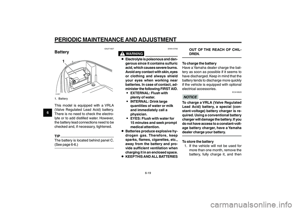
BatteryZAUM00**
1
1. BatteryThis model is equipped with a VRLA
(Valve Regulated Lead Acid) battery.
There is no need to check the electro-
lyte or to add distilled water. However,
the battery lead connections need to be
checked and, if necessary, tightened.TIP
The battery is located behind panel C.
(See page 6-6.)Battery
EWA10760
WARNING
8 88 8
8Electrolyte is poisonous and dan-
gerous since it contains sulfuric
acid, which causes severe burns.
Avoid any contact with skin, eyes
or clothing and always shield
your eyes when working near
batteries. In case of contact, ad-
minister the following FIRST AID.
9 99 9
9EXTERNAL: Flush with
plenty of water.
9 99 9
9INTERNAL: Drink large
quantities of water or milk
and immediately call a
physician.
9 99 9
9EYES: Flush with water for
15 minutes and seek prompt
medical attention.
8 88 8
8Batteries produce explosive hy-
drogen gas. Therefore, keep
sparks, flames, cigarettes, etc.,
away from the battery and pro-
vide sufficient ventilation when
charging it in an enclosed space.
8 88 8
8KEEP THIS AND ALL BATTERIESOUT OF THE REACH OF CHIL-
DREN.
To charge the battery
Have a Yamaha dealer charge the bat-
tery as soon as possible if it seems to
have discharged. Keep in mind that the
battery tends to discharge more quickly
if the vehicle is equipped with optional
electrical accessories.
ECA16520
NOTICETo charge a VRLA (Valve Regulated
Lead Acid) battery, a special (con-
stant-voltage) battery charger is re-
quired. Using a conventional battery
charger will damage the battery. If you
do not have access to a constant-volt-
age battery charger, have a Yamaha
dealer charge your battery.To store the battery
1. If the vehicle will not be used for
more than one month, remove the
battery, fully charge it, and then
Page 55 of 74
6-55
1
2
3
4
5
6
7
8
9
EAU1722A
PERIODIC MAINTENANCE AND ADJUSTMENT
6-20
place it in a cool, dry place.
NO-
TICE:
When removing the battery,
be sure the key is turned to
“OFF”, then disconnect the
negative lead before disconnect-
ing the positive lead.
[ECA16302]
2. If the battery will be stored for more
than two months, check it at least
once a month and fully charge it if
necessary.
3. Fully charge the battery before in-
stallation.
4. Before installation, make sure that
the battery leads are properly con-
nected to the battery terminals.
ECAT1053
NOTICE8 88 8
8Always keep the battery charged.
Storing a discharged battery can
cause permanent battery dam-
age.
8 88 8
8After installing the battery, be
sure to turn the main switch from
“ON” to “OFF” three times in 3
seconds intervals to initialize the
idle speed control system.Fuse, replacing
EAUT2023
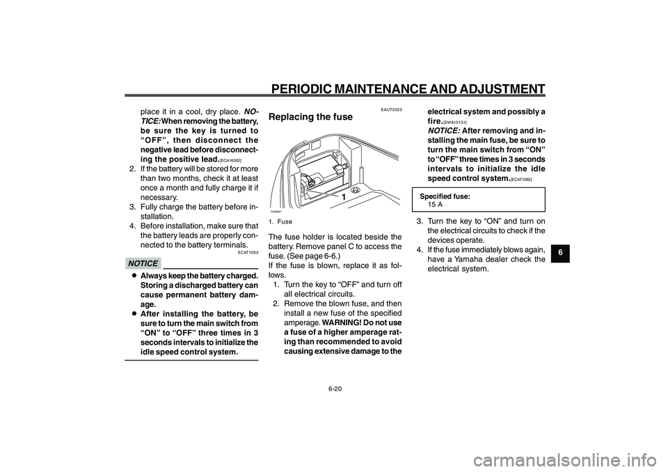
Replacing the fuseZAUM00**
1
1. FuseThe fuse holder is located beside the
battery. Remove panel C to access the
fuse. (See page 6-6.)
If the fuse is blown, replace it as fol-
lows.
1. Turn the key to “OFF” and turn off
all electrical circuits.
2. Remove the blown fuse, and then
install a new fuse of the specified
amperage. WARNING! Do not use
a fuse of a higher amperage rat-
ing than recommended to avoid
causing extensive damage to theelectrical system and possibly a
fire.
[EWA15131]
NOTICE:
After removing and in-
stalling the main fuse, be sure to
turn the main switch from “ON”
to “OFF” three times in 3 seconds
intervals to initialize the idle
speed control system.
[ECAT1062]
Specified fuse:
15 A3. Turn the key to “ON” and turn on
the electrical circuits to check if the
devices operate.
4. If the fuse immediately blows again,
have a Yamaha dealer check the
electrical system.
Page 59 of 74
6-59
1
2
3
4
5
6
7
8
9
EAU1722A
PERIODIC MAINTENANCE AND ADJUSTMENT
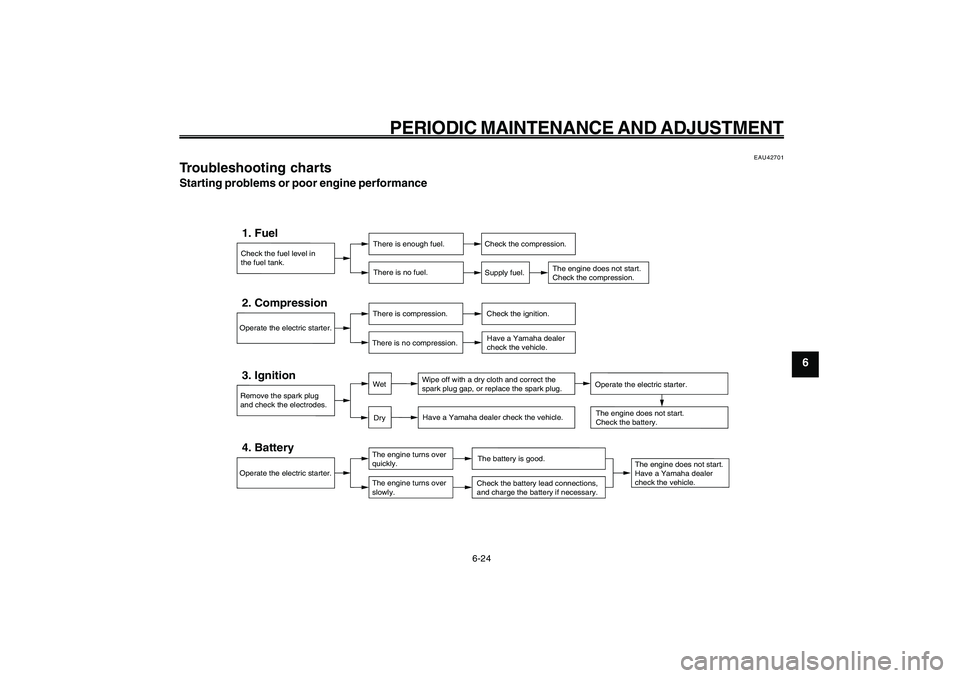
Troubleshooting char ts
Check the fuel level in
the fuel tank.1. Fuel
There is enough fuel.
There is no fuel.
Check the compression.
Supply fuel.
The engine does not start.
Check the compression.
Operate the electric starter.2. Compression
There is compression.
There is no compression.
Check the ignition.
Have a Yamaha dealer
check the vehicle.
Remove the spark plug
and check the electrodes.3. Ignition
Wipe off with a dry cloth and correct the
spark plug gap, or replace the spark plug.
Have a Yamaha dealer check the vehicle.
The engine does not start.
Have a Yamaha dealer
check the vehicle.
The engine does not start.
Check the battery.
Operate the electric starter.4. Battery
The engine turns over
quickly.
The engine turns over
slowly.
The battery is good.Check the battery lead connections,
and charge the battery if necessary.
DryWet
Operate the electric starter.
6-24
EAU42701
Troubleshooting chartsStarting problems or poor engine performance
Page 64 of 74

7-64
1
2
3
4
5
6
7
8
9
EAU25991
SCOOTER CARE AND STORAGE
7-4
stabilizer (if available) to prevent the
fuel tank from rusting and the fuel
from deteriorating.
3. Perform the following steps to pro-
tect the cylinder, piston rings, etc.
from corrosion.
a. Remove the spark plug cap and
spark plug.
b. Pour a teaspoonful of engine oil
into the spark plug bore.
c. Install the spark plug cap onto
the spark plug, and then place
the spark plug on the cylinder
head so that the electrodes are
grounded. (This will limit spark-
ing during the next step.)
d. Turn the engine over several
times with the starter. (This will
coat the cylinder wall with oil.)
e. Remove the spark plug cap from
the spark plug, and then install
the spark plug and the spark plug
cap. WARNING! To prevent dam-
age or injury from sparking,
make sure to ground the sparkplug electrodes while turning
the engine over.
[EWA10951]
4. Lubricate all control cables and the
pivoting points of all levers and
pedals as well as of the sidestand/
centerstand.
5. Check and, if necessary, correct
the tire air pressure, and then lift
the scooter so that both of its
wheels are off the ground. Alterna-
tively, turn the wheels a little every
month in order to prevent the tires
from becoming degraded in one
spot.
6. Cover the muffler outlet with a plas-
tic bag to prevent moisture from en-
tering it.
7. Remove the battery and fully charge
it. Store it in a cool, dry place and
charge it once a month. Do not store
the battery in an excessively cold
or warm place [less than 0 °C (30
°F) or more than 30 °C (90 °F)]. For
more information on storing the
battery, see page 6-19. Storage
EAU36561
StorageShort-term
Always store your scooter in a cool, dry
place and, if necessary, protect it against
dust with a porous cover.
ECA10820
NOTICE● ●● ●
●
Storing the scooter in a poorly
ventilated room or covering it
with a tarp, while it is still wet,
will allow water and humidity to
seep in and cause rust.
● ●● ●
●
To prevent corrosion, avoid
damp cellars, stables (because of
the presence of ammonia) and
areas where strong chemicals are
stored.
Long-term
Before storing your scooter for several
months:
1. Follow all the instructions in the
“Care” section of this chapter.
2. Fill up the fuel tank and add fuel
Page 67 of 74

8-67
1
2
3
4
5
6
7
8
9
EAU26320
SPECIFICATIONS
8-2 Trail
84.0 mm (3.31 in)
Front tireType
Tubeless
Size
120/90-10 57J
Manufacturer/model
CHENG SHIN / C-6022Rear tireType
Tubeless
Size
120/90-10 57J
Manufacturer/model
CHENG SHIN / C-6022LoadingMaximum load
177 kg (390 lb)Tire air pressure (measured on cold
tires)Front
175 kPa (1.75 kgf/cm
2, 25 psi, 1.75 bar)
Rear
175 kPa (1.75 kgf/cm2, 25 psi, 1.75 bar)
Front wheelWheel type
Cast wheel
Rim size
10 x 3.00Rear wheelWheel type
Cast wheelRim size
10 x 3.00
Front brakeType
Drum brake
Operation
Right hand operationRear brakeType
Drum brake
Operation
Left hand operationFront suspensionType
Telescopic fork
Spring/shock absorber type
Coil spring
Wheel travel
65.0 mm (2.56 in)Rear suspensionType
Unit swing
Spring/shock absorber type
Coil spring
Wheel travel
56.0 mm (2.20 in)Electrical systemIgnition system
TCI
Charging system
AC magnetoBatteryModel
GTX5L-BSVoltage, capacity
12 V, 4.0 Ah
HeadlightBulb type
Halogen bulbBulb voltage, wattage x quantityHeadlight
12 V, 35 W/35.0 W x 1
Tail/brake light
12 V, 5.0 W/21.0 W x 1
Front turn signal light
12 V, 10.0 W x 2
Rear turn signal light
12 V, 10.0 W x 2
Meter lighting
12 V, 1.7 W x 1
High beam indicator light
12 V, 1.7 W x 1
Turn signal indicator light
14 V, 3.0 W x 1
Coolant temperature warning light
12 V, 1.7 W x 1
Engine trouble warning light
12 V, 1.7 W x 1FusesMain fuse
15.0 A
Page 70 of 74
1
2
3
4
5
6
7
8
9
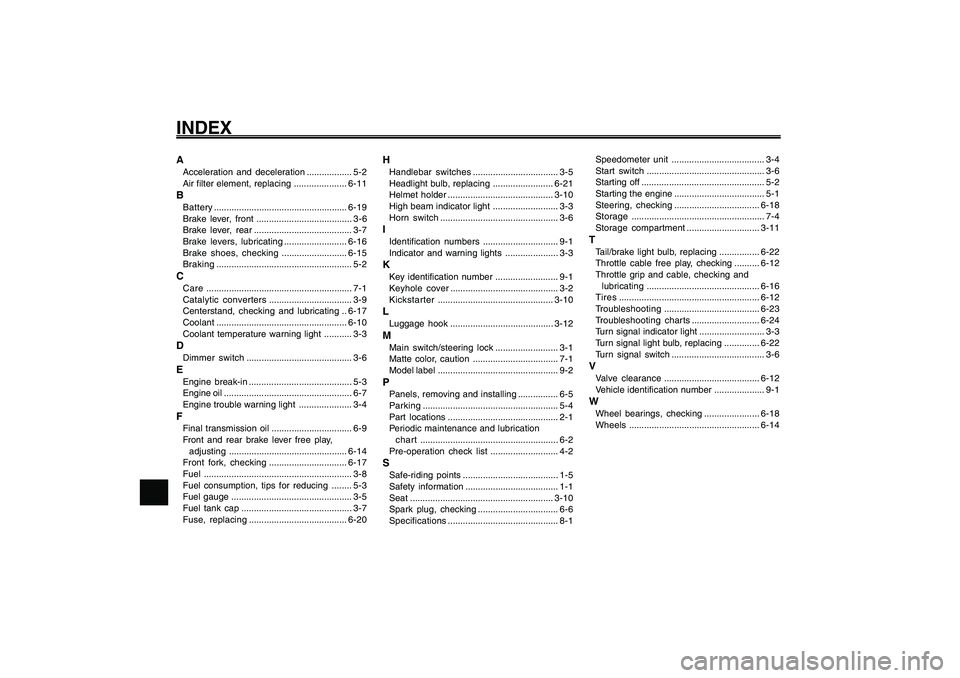
INDEXAAcceleration and deceleration.................. 5-2
Air filter element, replacing .....................6-11BBattery.....................................................6-19
Brake lever, front ...................................... 3-6
Brake lever, rear....................................... 3-7
Brake levers, lubricating.........................6-16
Brake shoes, checking ..........................6-15
Braking...................................................... 5-2CCare.......................................................... 7-1
Catalytic converters................................. 3-9
Centerstand, checking and lubricating ..6-17
Coolant....................................................6-10
Coolant temperature warning light ........... 3-3DDimmer switch.......................................... 3-6EEngine break-in ......................................... 5-3
Engine oil ................................................... 6-7
Engine trouble warning light ..................... 3-4FFinal transmission oil................................ 6-9
Front and rear brake lever free play,
adjusting...............................................6-14
Front fork, checking...............................6-17
Fuel........................................................... 3-8
Fuel consumption, tips for reducing ........ 5-3
Fuel gauge ................................................ 3-5
Fuel tank cap ............................................ 3-7
Fuse, replacing.......................................6-20
HHandlebar switches.................................. 3-5
Headlight bulb, replacing........................6-21
Helmet holder..........................................3-10
High beam indicator light .......................... 3-3
Horn switch............................................... 3-6IIdentification numbers.............................. 9-1
Indicator and warning lights ..................... 3-3KKey identification number......................... 9-1
Keyhole cover........................................... 3-2
Kickstarter..............................................3-10LLuggage hook .........................................3-12MMain switch/steering lock......................... 3-1
Matte color, caution .................................. 7-1
Model label................................................ 9-2PPanels, removing and installing................ 6-5
Parking...................................................... 5-4
Part locations............................................ 2-1
Periodic maintenance and lubrication
chart ....................................................... 6-2
Pre-operation check list........................... 4-2SSafe-riding points...................................... 1-5
Safety information..................................... 1-1
Seat .........................................................3-10
Spark plug, checking................................ 6-6
Specifications............................................ 8-1Speedometer unit..................................... 3-4
Start switch............................................... 3-6
Starting off ................................................. 5-2
Starting the engine.................................... 5-1
Steering, checking..................................6-18
Storage..................................................... 7-4
Storage compartment.............................3-11
TTail/brake light bulb, replacing ................6-22
Throttle cable free play, checking ..........6-12
Throttle grip and cable, checking and
lubricating.............................................6-16
Tires........................................................6-12
Troubleshooting......................................6-23
Troubleshooting charts...........................6-24
Turn signal indicator light.......................... 3-3
Turn signal light bulb, replacing ..............6-22
Turn signal switch ..................................... 3-6VValve clearance......................................6-12
Vehicle identification number .................... 9-1WWheel bearings, checking ......................6-18
Wheels....................................................6-14