brake light YAMAHA GIGGLE50 2009 Owners Manual
[x] Cancel search | Manufacturer: YAMAHA, Model Year: 2009, Model line: GIGGLE50, Model: YAMAHA GIGGLE50 2009Pages: 74, PDF Size: 0.9 MB
Page 6 of 74
1
2
3
4
5
6
7
8
9
EAU10210
TABLE OF CONTENTSSAFETY INFORMATION .................... 1-1
Further safe-riding points ................ 1-5
DESCRIPTION ................................... 2-1
Left view .......................................... 2-1
Right view ........................................ 2-2
Controls and instruments ................ 2-3
INSTRUMENT AND CONTROL FUNC-
TIONS................................................. 3-1
Main switch/steering lock ................ 3-1
Keyhole cover ................................. 3-2
Indicator and warning lights ............ 3-3
Speedometer unit............................ 3-4
Fuel gauge ...................................... 3-5
Handlebar switches........................ 3-5
Front brake lever ............................. 3-6
Rear brake lever ............................. 3-7
Fuel tank cap ................................... 3-7
Fuel................................................. 3-8
Catalytic converters ......................... 3-9
Kickstarter......................................3-10
Seat...............................................3-10
Helmet holder................................3-10
Storage compartment ....................3-11
Luggage hook...............................3-12
FOR YOUR SAFETY - PRE-OPERATION
CHECKS............................................ 4-1
Pre-operation check list .................. 4-2OPERATION AND IMPORTANT RIDING
POINTS............................................... 5-1
Starting the engine .......................... 5-1
Starting off ....................................... 5-2
Acceleration and deceleration........ 5-2
Braking............................................ 5-2
Tips for reducing fuel consumption . 5-3
Engine break-in............................... 5-3
Parking............................................ 5-4
PERIODIC MAINTENANCE AND
ADJUSTMENT................................... 6-1
Periodic maintenance and lubrication
chart............................................. 6-2
Removing and installing panels ..... 6-5
Checking the spark plug ................. 6-6
Engine oil........................................ 6-7
Final transmission oil ...................... 6-9
Coolant..........................................6-10
Replacing the air filter element .....6-11
Checking the throttle cable free
play............................................6-12
Valve clearance.............................6-12
Tires...............................................6-12
Cast wheels ...................................6-14
Adjusting the front and rear brake lever
free play .....................................6-14
Checking the front and rear brake
shoes.........................................6-15Checking and lubricating the throttle
grip and cable ............................6-16
Lubricating the front and rear brake
levers.........................................6-16
Checking and lubricating the
centerstand................................6-17
Checking the front fork ..................6-17
Checking the steering ...................6-18
Checking the wheel bearings .......6-18
Battery ...........................................6-19
Replacing the fuse ........................6-20
Replacing the headlight bulb ........6-21
Replacing the tail/brake light
bulb............................................6-22
Replacing a turn signal light
bulb............................................6-22
Troubleshooting............................6-23
Troubleshooting charts.................6-24
SCOOTER CARE AND STORAGE .... 7-1
Matte color caution .......................... 7-1
Care................................................. 7-1
Storage............................................ 7-4
SPECIFICATIONS.............................. 8-1
CONSUMER INFORMATION ............. 9-1
Identification numbers..................... 9-1
Page 12 of 74
1-12
EAU10221
Q QQ Q
Q
SAFETY INFORMATION
1
2
3
4
5
6
7
8
9
EAUT2030
Further safe-riding points●
Make sure to signal clearly when
making turns.
●
Braking can be extremely difficult
on a wet road. Avoid hard braking,
because the scooter could slide.
Apply the brakes slowly when stop-
ping on a wet surface.
●
Slow down as you approach a cor-
ner or turn. Once you have com-
pleted a turn, accelerate slowly.
●
Be careful when passing parked
cars. A driver might not see you and
open a door in your path.
●
Railroad crossings, streetcar rails,
iron plates on road construction
sites, and manhole covers become
extremely slippery when wet. Slow
down and cross them with caution.
Keep the scooter upright, otherwise
it could slide out from under you.
●
The brake lining could get wet when
you wash the scooter. After wash-
ing the scooter, check the brakes
before riding.
●
Always wear a helmet, gloves, trou-
sers (tapered around the cuff and
ankle so they do not flap), and a
bright colored jacket.
●
Do not carry too much luggage on
the scooter. An overloaded scooter
is unstable.
1-5
Safe-riding points
tric failure could result, which could
cause a dangerous loss of lights or
engine power.
Aftermarket Tires and Rims
The tires and rims that came with your
scooter were designed to match the
performance capabilities and to provide
the best combination of handling, brak-
ing, and comfort. Other tires, rims, sizes,
and combinations may not be appropri-
ate. Refer to page 6-12 for tire specifi-
cations and more information on replac-
ing your tires.
Page 15 of 74
2-15
1
2
3
4
5
6
7
8
9
EAU10401
DESCRIPTION
2-2
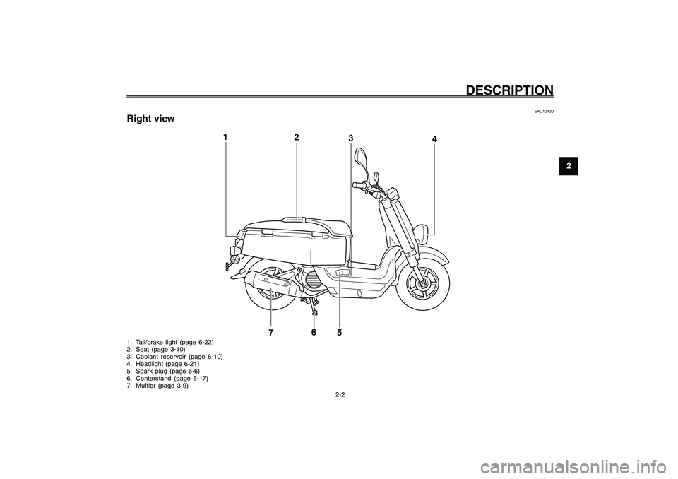
EAU10420
Right view1. Tail/brake light (page 6-22)
2. Seat (page 3-10)
3. Coolant reservoir (page 6-10)
4. Headlight (page 6-21)
5. Spark plug (page 6-6)
6. Centerstand (page 6-17)
7. Muffler (page 3-9)
2
3 1
4
5
6
7
Page 22 of 74
3-22
1
2
3
4
5
6
7
8
9
EAU1044E
INSTRUMENT AND CONTROL FUNCTIONSDimmer switch
Turn signal switch
Horn switch
Start switch
Brake lever, front
EAU12460
Turn signal switch “
4 44 4
4/
6 66 6
6”
To signal a right-hand turn, push this
switch to “6”. To signal a left-hand turn,
push this switch to “4”. When released,
the switch returns to the center position.
To cancel the turn signal lights, push the
switch in after it has returned to the cen-
ter position.
EAU12500
Horn switch “
* ** *
*”
Press this switch to sound the horn.
EAU12400
Dimmer switch “
& && &
&/
% %% %
%”
Set this switch to “&” for the high beam
and to “%” for the low beam.
EAUM1132
Start switch “
, ,, ,
,”
Push this switch while applying the front
or rear brake to crank the engine with
the starter. See page 5-1 for starting in-
structions prior to starting the engine.
3-6
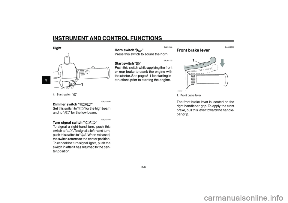
EAU12900
Front brake lever
1
ZAUM00**1. Front brake leverThe front brake lever is located on the
right handlebar grip. To apply the front
brake, pull this lever toward the handle-
bar grip. Right
ZAUM00**
1
1. Start switch ","
Page 32 of 74
5-32
1
2
3
4
5
6
7
8
9
EAU15943
OPERATION AND IMPORTANT RIDING POINTS
EAU15943
OPERATION AND IMPORTANT RIDING POINTS
5-1
Starting the engine
EAU15951
Read the Owner’s Manual carefully to
become familiar with all controls. If there
is a control or function you do not un-
derstand, ask your Yamaha dealer.
EWA10271
WARNING
Failure to familiarize yourself with
the controls can lead to loss of con-
trol, which could cause an accident
or injury.
EAU45310
TIP
This model is equipped with a lean angle
sensor to stop the engine in case of a
turnover. To start the engine after a turn-
over, be sure to turn the main switch to
“OFF” and then to “ON”. Failing to do so
will prevent the engine from starting
even though the engine will crank when
pushing the start switch.
EAUT2251
Starting the engine
ECA10250
NOTICESee page 5-3 for engine break-in in-
structions prior to operating the ve-
hicle for the first time.1. Turn the key to “ON”.
ECAT1070
NOTICEThe engine trouble warning light and
coolant temperature warning light
should come on for a few seconds,
then go off. If these warning lights do
not go off, have a Yamaha dealer check
their electrical circuits.2. Close the throttle completely.
3. Start the engine by pushing the
start switch while applying the front
or rear brake.
NOTICE:
For maxi-
mum engine life, never acceler-
ate hard when the engine is
cold!
[ECA11041]
If the engine does not start, release
the start switch, wait a few sec-
onds, and then try again. Each
starting attempt should be as short
as possible to preserve the battery.
Do not crank the engine more than
5 seconds on any one attempt. If
the engine does not start with the
starter motor, try using the
kickstar ter.
Page 57 of 74
6-57
1
2
3
4
5
6
7
8
9
EAU1722A
PERIODIC MAINTENANCE AND ADJUSTMENT
6-22
Tail/brake light bulb, replacing
Turn signal light bulb, replacing
EAU24204
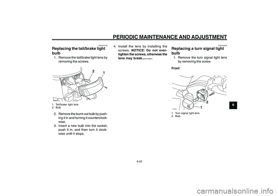
Replacing a turn signal light
bulb1. Remove the turn signal light lens
by removing the screw.
FrontZAUM00**
2
1
1. Turn signal light lens
2. Bulb
EAU24133
Replacing the tail/brake light
bulb1. Remove the tail/brake light lens by
removing the screws.ZAUM00**
1
2
1. Tail/brake light lens
2. Bulb2. Remove the burnt-out bulb by push-
ing it in and turning it counterclock-
wise.
3. Insert a new bulb into the socket,
push it in, and then turn it clock-
wise until it stops.4. Install the lens by installing the
screws.
NOTICE:
Do not over-
tighten the screws, otherwise the
lens may break.[ECA10681]
Page 62 of 74
7-62
1
2
3
4
5
6
7
8
9
EAU25991
SCOOTER CARE AND STORAGE
7-2
luted mild detergent with water
may be used. Be sure to rinse off
any detergent residue using
plenty of water, as it is harmful
to plastic parts.
● ●● ●
●
Do not use any harsh chemical
products on plastic parts. Be sure
to avoid using cloths or sponges
which have been in contact with
strong or abrasive cleaning prod-
ucts, solvent or thinner, fuel
(gasoline), rust removers or in-
hibitors, brake fluid, antifreeze or
electrolyte.
● ●● ●
●
Do not use high-pressure wash-
ers or steam-jet cleaners since
they cause water seepage and
deterioration in the following ar-
eas: seals (of wheel and
swingarm bearings, fork and
brakes), electric components
(couplers, connectors, instru-
ments, switches and lights),
breather hoses and vents.
● ●● ●
●
For scooters equipped with a
windshield: Do not use strongcleaners or hard sponges as they
will cause dulling or scratching.
Some cleaning compounds for
plastic may leave scratches on
the windshield. Test the product
on a small hidden part of the
windshield to make sure that it
does not leave any marks. If the
windshield is scratched, use a
quality plastic polishing com-
pound after washing.
After normal use
Remove dirt with warm water, a mild
detergent, and a soft, clean sponge, and
then rinse thoroughly with clean water.
Use a toothbrush or bottlebrush for hard-
to-reach areas. Stubborn dirt and insects
will come off more easily if the area is
covered with a wet cloth for a few min-
utes before cleaning.After riding in the rain, near the sea oron salt-sprayed roads
Since sea salt or salt sprayed on the
roads during winter are extremely corro-sive in combination with water, carry out
the following steps after each ride in the
rain, near the sea or on salt-sprayed
roads.
TIP
Salt sprayed on roads in the winter may
remain well into spring.1. Clean the scooter with cold water
and a mild detergent after the en-
gine has cooled down.
NOTICE:
Do
not use warm water since it in-
creases the corrosive action of
the salt.
[ECA10791]
2. Apply a corrosion protection spray
on all metal, including chrome- and
nickel-plated, surfaces to prevent
corrosion.
After cleaning
1. Dry the scooter with a chamois or
an absorbing cloth.
2. Use a chrome polish to shine
chrome, aluminum and stainless-
steel parts, including the exhaust
Page 63 of 74
7-63
1
2
3
4
5
6
7
8
9
EAU25991
SCOOTER CARE AND STORAGE
7-3
system. (Even the thermally in-
duced discoloring of stainless-steel
exhaust systems can be removed
through polishing.)
3. To prevent corrosion, it is recom-
mended to apply a corrosion pro-
tection spray on all metal, includ-
ing chrome- and nickel-plated, sur-
faces.
4. Use spray oil as a universal cleaner
to remove any remaining dirt.
5. Touch up minor paint damage
caused by stones, etc.
6. Wax all painted surfaces.
7. Let the scooter dry completely be-
fore storing or covering it.
EWA10941
WARNING
Contaminants on the brakes or tires
can cause loss of control.● ●● ●
●
Make sure that there is no oil or
wax on the brakes or tires. If nec-
essary, clean the brake discs and
brake linings with a regular brake
disc cleaner or acetone, and
wash the tires with warm waterand a mild detergent.
● ●● ●
●
Before operating the scooter test
its braking performance and cor-
nering behavior.
ECA10800
NOTICE● ●● ●
●
Apply spray oil and wax spar-
ingly and make sure to wipe off
any excess.
● ●● ●
●
Never apply oil or wax to any rub-
ber and plastic parts, but treat
them with a suitable care prod-
uct.
● ●● ●
●
Avoid using abrasive polishing
compounds as they will wear
away the paint.
TIP●
Consult a Yamaha dealer for advice
on what products to use.
●
Washing, rainy weather or humid
climates can cause the headlight
lens to fog. Turning the headlight onfor a short period of time will help
remove the moisture from the lens.
Page 67 of 74

8-67
1
2
3
4
5
6
7
8
9
EAU26320
SPECIFICATIONS
8-2 Trail
84.0 mm (3.31 in)
Front tireType
Tubeless
Size
120/90-10 57J
Manufacturer/model
CHENG SHIN / C-6022Rear tireType
Tubeless
Size
120/90-10 57J
Manufacturer/model
CHENG SHIN / C-6022LoadingMaximum load
177 kg (390 lb)Tire air pressure (measured on cold
tires)Front
175 kPa (1.75 kgf/cm
2, 25 psi, 1.75 bar)
Rear
175 kPa (1.75 kgf/cm2, 25 psi, 1.75 bar)
Front wheelWheel type
Cast wheel
Rim size
10 x 3.00Rear wheelWheel type
Cast wheelRim size
10 x 3.00
Front brakeType
Drum brake
Operation
Right hand operationRear brakeType
Drum brake
Operation
Left hand operationFront suspensionType
Telescopic fork
Spring/shock absorber type
Coil spring
Wheel travel
65.0 mm (2.56 in)Rear suspensionType
Unit swing
Spring/shock absorber type
Coil spring
Wheel travel
56.0 mm (2.20 in)Electrical systemIgnition system
TCI
Charging system
AC magnetoBatteryModel
GTX5L-BSVoltage, capacity
12 V, 4.0 Ah
HeadlightBulb type
Halogen bulbBulb voltage, wattage x quantityHeadlight
12 V, 35 W/35.0 W x 1
Tail/brake light
12 V, 5.0 W/21.0 W x 1
Front turn signal light
12 V, 10.0 W x 2
Rear turn signal light
12 V, 10.0 W x 2
Meter lighting
12 V, 1.7 W x 1
High beam indicator light
12 V, 1.7 W x 1
Turn signal indicator light
14 V, 3.0 W x 1
Coolant temperature warning light
12 V, 1.7 W x 1
Engine trouble warning light
12 V, 1.7 W x 1FusesMain fuse
15.0 A
Page 70 of 74
1
2
3
4
5
6
7
8
9
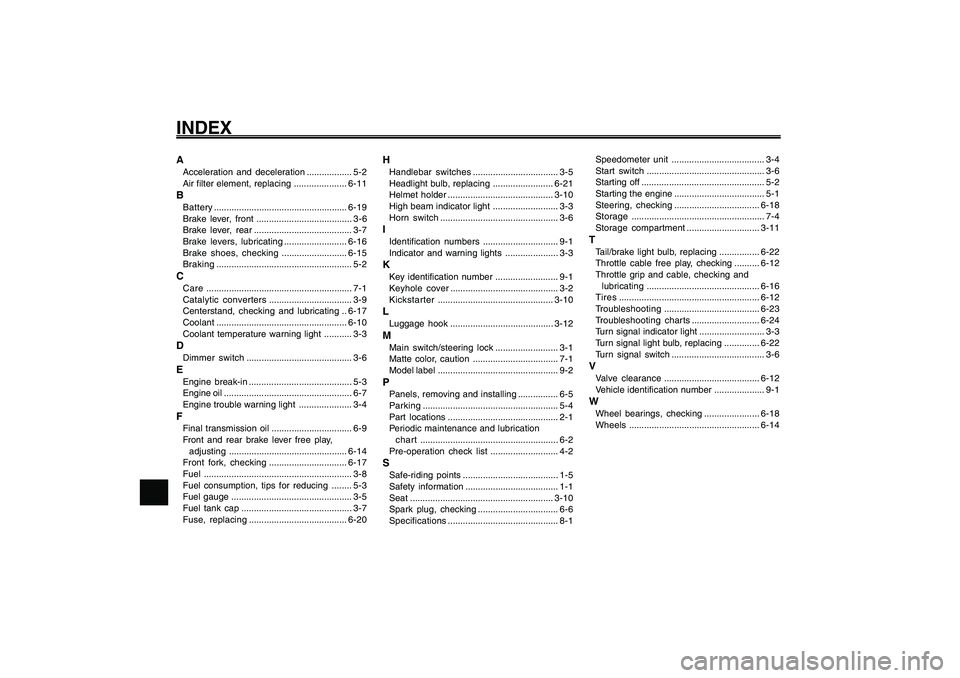
INDEXAAcceleration and deceleration.................. 5-2
Air filter element, replacing .....................6-11BBattery.....................................................6-19
Brake lever, front ...................................... 3-6
Brake lever, rear....................................... 3-7
Brake levers, lubricating.........................6-16
Brake shoes, checking ..........................6-15
Braking...................................................... 5-2CCare.......................................................... 7-1
Catalytic converters................................. 3-9
Centerstand, checking and lubricating ..6-17
Coolant....................................................6-10
Coolant temperature warning light ........... 3-3DDimmer switch.......................................... 3-6EEngine break-in ......................................... 5-3
Engine oil ................................................... 6-7
Engine trouble warning light ..................... 3-4FFinal transmission oil................................ 6-9
Front and rear brake lever free play,
adjusting...............................................6-14
Front fork, checking...............................6-17
Fuel........................................................... 3-8
Fuel consumption, tips for reducing ........ 5-3
Fuel gauge ................................................ 3-5
Fuel tank cap ............................................ 3-7
Fuse, replacing.......................................6-20
HHandlebar switches.................................. 3-5
Headlight bulb, replacing........................6-21
Helmet holder..........................................3-10
High beam indicator light .......................... 3-3
Horn switch............................................... 3-6IIdentification numbers.............................. 9-1
Indicator and warning lights ..................... 3-3KKey identification number......................... 9-1
Keyhole cover........................................... 3-2
Kickstarter..............................................3-10LLuggage hook .........................................3-12MMain switch/steering lock......................... 3-1
Matte color, caution .................................. 7-1
Model label................................................ 9-2PPanels, removing and installing................ 6-5
Parking...................................................... 5-4
Part locations............................................ 2-1
Periodic maintenance and lubrication
chart ....................................................... 6-2
Pre-operation check list........................... 4-2SSafe-riding points...................................... 1-5
Safety information..................................... 1-1
Seat .........................................................3-10
Spark plug, checking................................ 6-6
Specifications............................................ 8-1Speedometer unit..................................... 3-4
Start switch............................................... 3-6
Starting off ................................................. 5-2
Starting the engine.................................... 5-1
Steering, checking..................................6-18
Storage..................................................... 7-4
Storage compartment.............................3-11
TTail/brake light bulb, replacing ................6-22
Throttle cable free play, checking ..........6-12
Throttle grip and cable, checking and
lubricating.............................................6-16
Tires........................................................6-12
Troubleshooting......................................6-23
Troubleshooting charts...........................6-24
Turn signal indicator light.......................... 3-3
Turn signal light bulb, replacing ..............6-22
Turn signal switch ..................................... 3-6VValve clearance......................................6-12
Vehicle identification number .................... 9-1WWheel bearings, checking ......................6-18
Wheels....................................................6-14