key YAMAHA GIGGLE50 2009 Owners Manual
[x] Cancel search | Manufacturer: YAMAHA, Model Year: 2009, Model line: GIGGLE50, Model: YAMAHA GIGGLE50 2009Pages: 74, PDF Size: 0.9 MB
Page 4 of 74
1
2
3
4
5
6
7
8
9
EAU10122
IMPORTANT MANUAL INFORMATIONQ
EAU10132
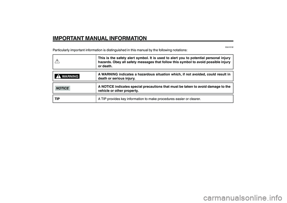
Particularly important information is distinguished in this manual by the following notations:
This is the safety alert symbol. It is used to alert you to potential personal injury
hazards. Obey all safety messages that follow this symbol to avoid possible injury
or death.
A WARNING indicates a hazardous situation which, if not avoided, could result in
death or serious injury.
A NOTICE indicates special precautions that must be taken to avoid damage to the
vehicle or other property.
A TIP provides key information to make procedures easier or clearer.
WARNING
NOTICETIP
Page 6 of 74
1
2
3
4
5
6
7
8
9
EAU10210
TABLE OF CONTENTSSAFETY INFORMATION .................... 1-1
Further safe-riding points ................ 1-5
DESCRIPTION ................................... 2-1
Left view .......................................... 2-1
Right view ........................................ 2-2
Controls and instruments ................ 2-3
INSTRUMENT AND CONTROL FUNC-
TIONS................................................. 3-1
Main switch/steering lock ................ 3-1
Keyhole cover ................................. 3-2
Indicator and warning lights ............ 3-3
Speedometer unit............................ 3-4
Fuel gauge ...................................... 3-5
Handlebar switches........................ 3-5
Front brake lever ............................. 3-6
Rear brake lever ............................. 3-7
Fuel tank cap ................................... 3-7
Fuel................................................. 3-8
Catalytic converters ......................... 3-9
Kickstarter......................................3-10
Seat...............................................3-10
Helmet holder................................3-10
Storage compartment ....................3-11
Luggage hook...............................3-12
FOR YOUR SAFETY - PRE-OPERATION
CHECKS............................................ 4-1
Pre-operation check list .................. 4-2OPERATION AND IMPORTANT RIDING
POINTS............................................... 5-1
Starting the engine .......................... 5-1
Starting off ....................................... 5-2
Acceleration and deceleration........ 5-2
Braking............................................ 5-2
Tips for reducing fuel consumption . 5-3
Engine break-in............................... 5-3
Parking............................................ 5-4
PERIODIC MAINTENANCE AND
ADJUSTMENT................................... 6-1
Periodic maintenance and lubrication
chart............................................. 6-2
Removing and installing panels ..... 6-5
Checking the spark plug ................. 6-6
Engine oil........................................ 6-7
Final transmission oil ...................... 6-9
Coolant..........................................6-10
Replacing the air filter element .....6-11
Checking the throttle cable free
play............................................6-12
Valve clearance.............................6-12
Tires...............................................6-12
Cast wheels ...................................6-14
Adjusting the front and rear brake lever
free play .....................................6-14
Checking the front and rear brake
shoes.........................................6-15Checking and lubricating the throttle
grip and cable ............................6-16
Lubricating the front and rear brake
levers.........................................6-16
Checking and lubricating the
centerstand................................6-17
Checking the front fork ..................6-17
Checking the steering ...................6-18
Checking the wheel bearings .......6-18
Battery ...........................................6-19
Replacing the fuse ........................6-20
Replacing the headlight bulb ........6-21
Replacing the tail/brake light
bulb............................................6-22
Replacing a turn signal light
bulb............................................6-22
Troubleshooting............................6-23
Troubleshooting charts.................6-24
SCOOTER CARE AND STORAGE .... 7-1
Matte color caution .......................... 7-1
Care................................................. 7-1
Storage............................................ 7-4
SPECIFICATIONS.............................. 8-1
CONSUMER INFORMATION ............. 9-1
Identification numbers..................... 9-1
Page 17 of 74
3-17
1
2
3
4
5
6
7
8
9
EAU1044E
INSTRUMENT AND CONTROL FUNCTIONS
3-1
Main switch/steering lock
EAU10460
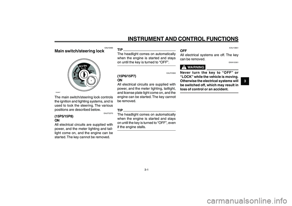
Main switch/steering lockZAUM00**The main switch/steering lock controls
the ignition and lighting systems, and is
used to lock the steering. The various
positions are described below.
EAUT2270
(15P5/15P8)
ON
All electrical circuits are supplied with
power, and the meter lighting and tail-
light come on, and the engine can be
started. The key cannot be removed.
EAUT2060
(15P6/15P7)
ON
All electrical circuits are supplied with
power, and the meter lighting, taillight,
and license plate light come on, and the
engine can be started. The key cannot
be removed.TIP
The headlight comes on automatically
when the engine is started and stays
on until the key is turned to “OFF”, even
if the engine stalls.
EAU10661
OFF
All electrical systems are off. The key
can be removed.
EWA10061
WARNING
Never turn the key to “OFF” or
“LOCK” while the vehicle is moving.
Otherwise the electrical systems will
be switched off, which may result in
loss of control or an accident.
EAU1044E
INSTRUMENT AND CONTROL FUNCTIONS
TIP
The headlight comes on automatically
when the engine is started and stays
on until the key is turned to “OFF”.
Page 18 of 74
3-18
1
2
3
4
5
6
7
8
9
EAU1044E
INSTRUMENT AND CONTROL FUNCTIONS
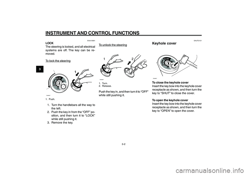
To unloc
k the steer
ing
12
ZAUM00**1. Turn.
2. Release.Push the key in, and then turn it to “OFF”
while still pushing it.
EAUT2121
Keyhole coverZAUM00**To close the keyhole cover
Insert the key bow into the keyhole cover
receptacle as shown, and then turn the
key to “SHUT” to close the cover.
To open the keyhole cover
Insert the key bow into the keyhole cover
receptacle as shown, and then turn the
key to “OPEN” to open the cover. Keyhole cover
3-2
EAU10681
LOCK
The steering is locked, and all electrical
systems are off. The key can be re-
moved.To loc
k the steer
ing
ZAUM00**
1
1. Push.1. Turn the handlebars all the way to
the left.
2. Push the key in from the “OFF” po-
sition, and then turn it to “LOCK”
while still pushing it.
3. Remove the key.
Page 19 of 74
3-19
1
2
3
4
5
6
7
8
9
EAU1044E
INSTRUMENT AND CONTROL FUNCTIONS
EAU11020
Turn signal indicator light “
5 55 5
5”
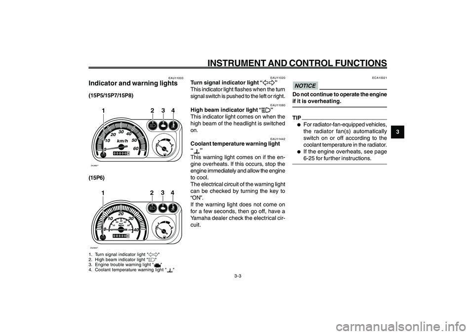
This indicator light flashes when the turn
signal switch is pushed to the left or right.
EAU11080
High beam indicator light “
& && &
&”
This indicator light comes on when the
high beam of the headlight is switched
on. Indicator and warning lights
Turn signal indicator light
High beam indicator light
Coolant temperature warning light
EAU11442
Coolant temperature warning light
“
”
This warning light comes on if the en-
gine overheats. If this occurs, stop the
engine immediately and allow the engine
to cool.
The electrical circuit of the warning light
can be checked by turning the key to
“ON”.
If the warning light does not come on
for a few seconds, then go off, have a
Yamaha dealer check the electrical cir-
cuit.
3-3
EAU11003
Indicator and warning lights(15P5/15P7/15P8)ZAUM00**
3
24
1
(15P6)ZAUM00**
0102030
40
50
60
3
24
1
1. Turn signal indicator light "5"
2. High beam indicator light "&"
3. Engine trouble warning light "
"
4. Coolant temperature warning light "
"
ECA10021
NOTICEDo not continue to operate the engine
if it is overheating.TIP●
For radiator-fan-equipped vehicles,
the radiator fan(s) automatically
switch on or off according to the
coolant temperature in the radiator.
●
If the engine overheats, see page
6-25 for further instructions.
Page 20 of 74
3-20
1
2
3
4
5
6
7
8
9
EAU1044E
INSTRUMENT AND CONTROL FUNCTIONS
3-4
EAUT2310
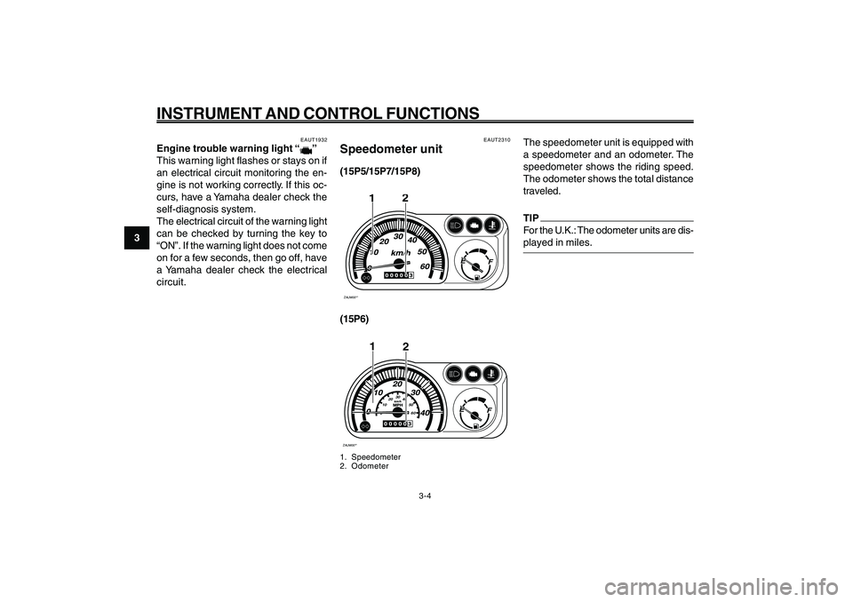
Speedometer unit(15P5/15P7/15P8)ZAUM00**
2
1
(15P6)ZAUM00**
2
0102030
40
50
60
1
1. Speedometer
2. Odometer
Engine trouble warning light
Speedometer unit
The speedometer unit is equipped with
a speedometer and an odometer. The
speedometer shows the riding speed.
The odometer shows the total distance
traveled.
TIP
For the U.K.: The odometer units are dis-
played in miles.
EAUT1932
Engine trouble warning light “
”
This warning light flashes or stays on if
an electrical circuit monitoring the en-
gine is not working correctly. If this oc-
curs, have a Yamaha dealer check the
self-diagnosis system.
The electrical circuit of the warning light
can be checked by turning the key to
“ON”. If the warning light does not come
on for a few seconds, then go off, have
a Yamaha dealer check the electrical
circuit.
Page 23 of 74
3-23
1
2
3
4
5
6
7
8
9
EAU1044E
INSTRUMENT AND CONTROL FUNCTIONS
3-7
Brake lever, rear
Fuel tank cap
EAUT2281
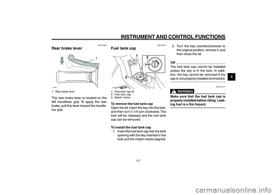
Fuel tank capZAUM00**
3
1
2
1. Fuel tank cap lid
2. Fuel tank cap
3. Match marksTo remove the fuel tank cap
Open the lid, insert the key into the lock,
and then turn it 1/4 turn clockwise. The
lock will be released and the fuel tank
cap can be removed.
To install the fuel tank cap
1. Inser t the fuel tank cap into the tank
opening with the key inserted in the
lock and the match marks aligned.2. Turn the key counterclockwise to
the original position, remove it, and
then close the lid.
TIP
The fuel tank cap cannot be installed
unless the key is in the lock. In addi-
tion, the key cannot be removed if the
cap is not properly installed and locked.
EWA10131
WARNING
Make sure that the fuel tank cap is
properly installed before riding. Leak-
ing fuel is a fire hazard.
EAU12950
Rear brake lever
1
ZAUM00**1. Rear brake leverThe rear brake lever is located on the
left handlebar grip. To apply the rear
brake, pull this lever toward the handle-
bar grip.
Page 26 of 74
3-26
1
2
3
4
5
6
7
8
9
EAU1044E
INSTRUMENT AND CONTROL FUNCTIONS
3-10
Kickstarter
Seat
Helmet holder
EAU13891
SeatZAUM00**To open the seat
1. Insert the key in the lock, and then
turn it as shown.
2. Fold the seat up.
To close the seat
1. Fold the seat down, and then push
it down to lock it in place.
2. Remove the key.TIP
Make sure that the seat is properly se-
cured before riding.
EAUT2041
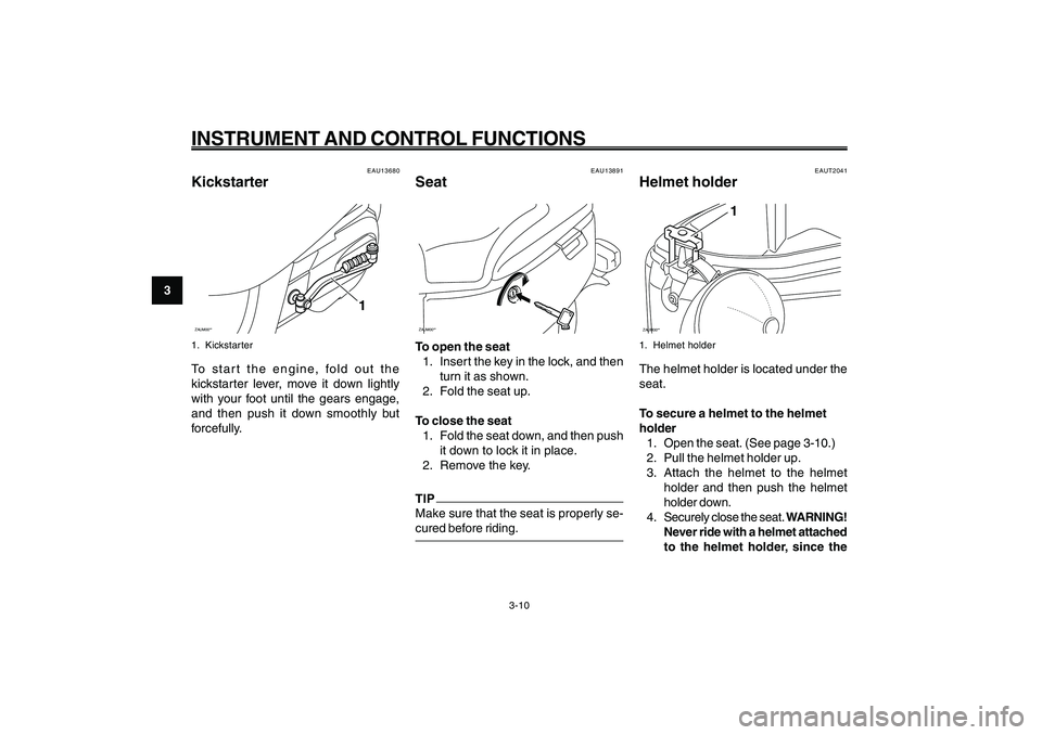
Helmet holderZAUM00**
1
1. Helmet holderThe helmet holder is located under the
seat.
To secure a helmet to the helmet
holder
1. Open the seat. (See page 3-10.)
2. Pull the helmet holder up.
3. Attach the helmet to the helmet
holder and then push the helmet
holder down.
4. Securely close the seat. WARNING!
Never ride with a helmet attached
to the helmet holder, since the
EAU13680
KickstarterZAUM00**
1
1. KickstarterTo start the engine, fold out the
kickstarter lever, move it down lightly
with your foot until the gears engage,
and then push it down smoothly but
forcefully.
Page 32 of 74
5-32
1
2
3
4
5
6
7
8
9
EAU15943
OPERATION AND IMPORTANT RIDING POINTS
EAU15943
OPERATION AND IMPORTANT RIDING POINTS
5-1
Starting the engine
EAU15951
Read the Owner’s Manual carefully to
become familiar with all controls. If there
is a control or function you do not un-
derstand, ask your Yamaha dealer.
EWA10271
WARNING
Failure to familiarize yourself with
the controls can lead to loss of con-
trol, which could cause an accident
or injury.
EAU45310
TIP
This model is equipped with a lean angle
sensor to stop the engine in case of a
turnover. To start the engine after a turn-
over, be sure to turn the main switch to
“OFF” and then to “ON”. Failing to do so
will prevent the engine from starting
even though the engine will crank when
pushing the start switch.
EAUT2251
Starting the engine
ECA10250
NOTICESee page 5-3 for engine break-in in-
structions prior to operating the ve-
hicle for the first time.1. Turn the key to “ON”.
ECAT1070
NOTICEThe engine trouble warning light and
coolant temperature warning light
should come on for a few seconds,
then go off. If these warning lights do
not go off, have a Yamaha dealer check
their electrical circuits.2. Close the throttle completely.
3. Start the engine by pushing the
start switch while applying the front
or rear brake.
NOTICE:
For maxi-
mum engine life, never acceler-
ate hard when the engine is
cold!
[ECA11041]
If the engine does not start, release
the start switch, wait a few sec-
onds, and then try again. Each
starting attempt should be as short
as possible to preserve the battery.
Do not crank the engine more than
5 seconds on any one attempt. If
the engine does not start with the
starter motor, try using the
kickstar ter.
Page 35 of 74
5-35
1
2
3
4
5
6
7
8
9
EAU15943
OPERATION AND IMPORTANT RIDING POINTS
EAU17213
ParkingWhen parking, stop the engine, and
then remove the key from the main
switch.
EWA10311
WARNING
● ●● ●
●
Since the engine and exhaust
system can become very hot,
park in a place where pedestri-
ans or children are not likely to
touch them and be burned.
● ●● ●
●
Do not park on a slope or on soft
ground, otherwise the vehicle
may overturn, increasing the risk
of a fuel leak and fire.
● ●● ●
●
Do not park near grass or other
flammable materials which
might catch fire.
Parking
5-4