warning YAMAHA GIGGLE50 2009 Owners Manual
[x] Cancel search | Manufacturer: YAMAHA, Model Year: 2009, Model line: GIGGLE50, Model: YAMAHA GIGGLE50 2009Pages: 74, PDF Size: 0.9 MB
Page 3 of 74
1
2
3
4
5
6
7
8
9
EAU10050
INTRODUCTION
EAU10113
Welcome to the Yamaha world of motorcycling!
As the owner of the XF50E, you are benefiting from Yamaha’s vast experience and newest technology regarding the design
and manufacture of high-quality products, which have earned Yamaha a reputation for dependability.
Please take the time to read this manual thoroughly, so as to enjoy all advantages of your XF50E. The Owner’s Manual does
not only instruct you in how to operate, inspect and maintain your scooter, but also in how to safeguard yourself and others
from trouble and injury.
In addition, the many tips given in this manual will help keep your scooter in the best possible condition. If you have any
further questions, do not hesitate to contact your Yamaha dealer.
The Yamaha team wishes you many safe and pleasant rides. So, remember to put safety first!
Yamaha continually seeks advancements in product design and quality. Therefore, while this manual contains the most
current product information available at the time of printing, there may be minor discrepancies between your scooter and this
manual. If there is any question concerning this manual, please consult a Yamaha dealer.
EWA12411
WARNING
Please read this manual carefully and completely before operating this scooter.
Page 4 of 74
1
2
3
4
5
6
7
8
9
EAU10122
IMPORTANT MANUAL INFORMATIONQ
EAU10132
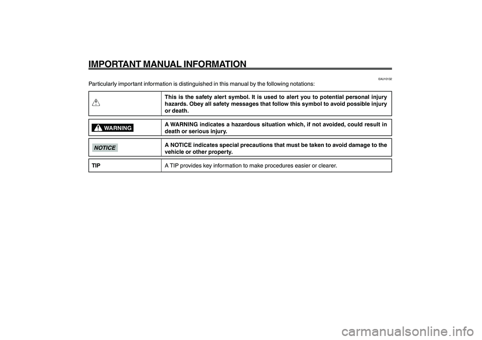
Particularly important information is distinguished in this manual by the following notations:
This is the safety alert symbol. It is used to alert you to potential personal injury
hazards. Obey all safety messages that follow this symbol to avoid possible injury
or death.
A WARNING indicates a hazardous situation which, if not avoided, could result in
death or serious injury.
A NOTICE indicates special precautions that must be taken to avoid damage to the
vehicle or other property.
A TIP provides key information to make procedures easier or clearer.
WARNING
NOTICETIP
Page 6 of 74
1
2
3
4
5
6
7
8
9
EAU10210
TABLE OF CONTENTSSAFETY INFORMATION .................... 1-1
Further safe-riding points ................ 1-5
DESCRIPTION ................................... 2-1
Left view .......................................... 2-1
Right view ........................................ 2-2
Controls and instruments ................ 2-3
INSTRUMENT AND CONTROL FUNC-
TIONS................................................. 3-1
Main switch/steering lock ................ 3-1
Keyhole cover ................................. 3-2
Indicator and warning lights ............ 3-3
Speedometer unit............................ 3-4
Fuel gauge ...................................... 3-5
Handlebar switches........................ 3-5
Front brake lever ............................. 3-6
Rear brake lever ............................. 3-7
Fuel tank cap ................................... 3-7
Fuel................................................. 3-8
Catalytic converters ......................... 3-9
Kickstarter......................................3-10
Seat...............................................3-10
Helmet holder................................3-10
Storage compartment ....................3-11
Luggage hook...............................3-12
FOR YOUR SAFETY - PRE-OPERATION
CHECKS............................................ 4-1
Pre-operation check list .................. 4-2OPERATION AND IMPORTANT RIDING
POINTS............................................... 5-1
Starting the engine .......................... 5-1
Starting off ....................................... 5-2
Acceleration and deceleration........ 5-2
Braking............................................ 5-2
Tips for reducing fuel consumption . 5-3
Engine break-in............................... 5-3
Parking............................................ 5-4
PERIODIC MAINTENANCE AND
ADJUSTMENT................................... 6-1
Periodic maintenance and lubrication
chart............................................. 6-2
Removing and installing panels ..... 6-5
Checking the spark plug ................. 6-6
Engine oil........................................ 6-7
Final transmission oil ...................... 6-9
Coolant..........................................6-10
Replacing the air filter element .....6-11
Checking the throttle cable free
play............................................6-12
Valve clearance.............................6-12
Tires...............................................6-12
Cast wheels ...................................6-14
Adjusting the front and rear brake lever
free play .....................................6-14
Checking the front and rear brake
shoes.........................................6-15Checking and lubricating the throttle
grip and cable ............................6-16
Lubricating the front and rear brake
levers.........................................6-16
Checking and lubricating the
centerstand................................6-17
Checking the front fork ..................6-17
Checking the steering ...................6-18
Checking the wheel bearings .......6-18
Battery ...........................................6-19
Replacing the fuse ........................6-20
Replacing the headlight bulb ........6-21
Replacing the tail/brake light
bulb............................................6-22
Replacing a turn signal light
bulb............................................6-22
Troubleshooting............................6-23
Troubleshooting charts.................6-24
SCOOTER CARE AND STORAGE .... 7-1
Matte color caution .......................... 7-1
Care................................................. 7-1
Storage............................................ 7-4
SPECIFICATIONS.............................. 8-1
CONSUMER INFORMATION ............. 9-1
Identification numbers..................... 9-1
Page 8 of 74
1-8
EAU10221
Q QQ Q
Q
SAFETY INFORMATION
1
2
3
4
5
6
7
8
9
EAU10221
Q QQ Q
Q
SAFETY INFORMATION
1-1
Safety information
EAU10263
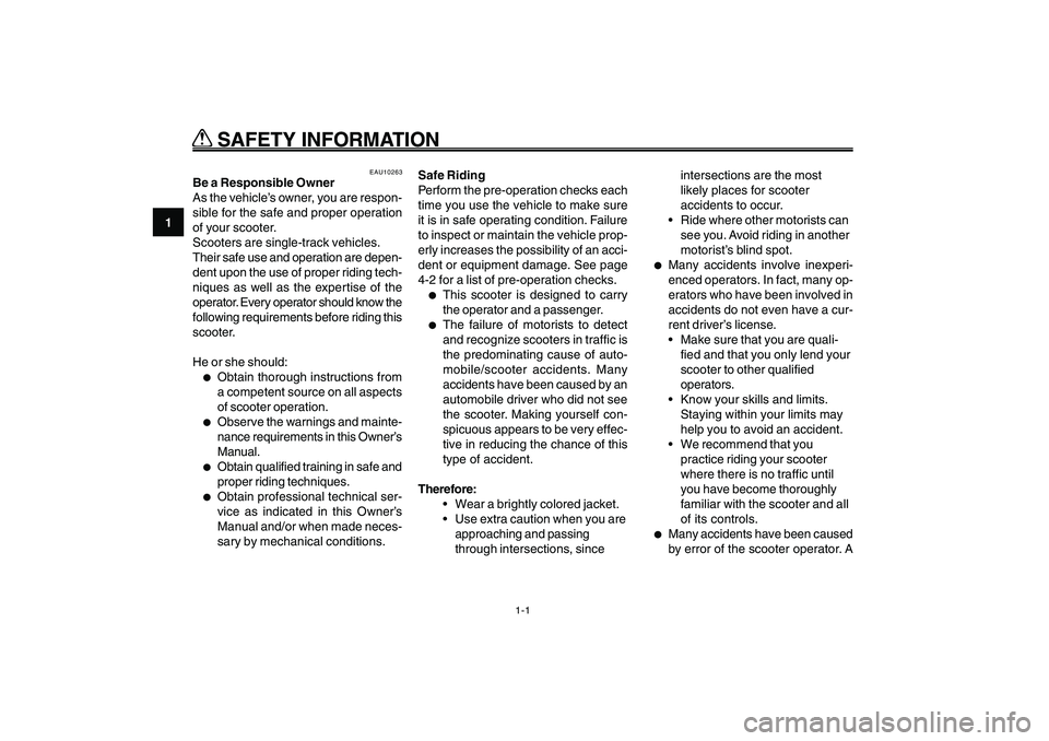
Be a Responsible Owner
As the vehicle’s owner, you are respon-
sible for the safe and proper operation
of your scooter.
Scooters are single-track vehicles.
Their safe use and operation are depen-
dent upon the use of proper riding tech-
niques as well as the expertise of the
operator. Every operator should know the
following requirements before riding this
scooter.
He or she should:●
Obtain thorough instructions from
a competent source on all aspects
of scooter operation.
●
Observe the warnings and mainte-
nance requirements in this Owner’s
Manual.
●
Obtain qualified training in safe and
proper riding techniques.
●
Obtain professional technical ser-
vice as indicated in this Owner’s
Manual and/or when made neces-
sary by mechanical conditions.Safe Riding
Perform the pre-operation checks each
time you use the vehicle to make sure
it is in safe operating condition. Failure
to inspect or maintain the vehicle prop-
erly increases the possibility of an acci-
dent or equipment damage. See page
4-2 for a list of pre-operation checks.
●
This scooter is designed to carry
the operator and a passenger.
●
The failure of motorists to detect
and recognize scooters in traffic is
the predominating cause of auto-
mobile/scooter accidents. Many
accidents have been caused by an
automobile driver who did not see
the scooter. Making yourself con-
spicuous appears to be very effec-
tive in reducing the chance of this
type of accident.
Therefore:
Wear a brightly colored jacket.
Use extra caution when you are
approaching and passing
through intersections, sinceintersections are the most
likely places for scooter
accidents to occur.
Ride where other motorists can
see you. Avoid riding in another
motorist’s blind spot.
●
Many accidents involve inexperi-
enced operators. In fact, many op-
erators who have been involved in
accidents do not even have a cur-
rent driver’s license.
Make sure that you are quali-
fied and that you only lend your
scooter to other qualified
operators.
Know your skills and limits.
Staying within your limits may
help you to avoid an accident.
We recommend that you
practice riding your scooter
where there is no traffic until
you have become thoroughly
familiar with the scooter and all
of its controls.
●
Many accidents have been caused
by error of the scooter operator. A
Page 17 of 74
3-17
1
2
3
4
5
6
7
8
9
EAU1044E
INSTRUMENT AND CONTROL FUNCTIONS
3-1
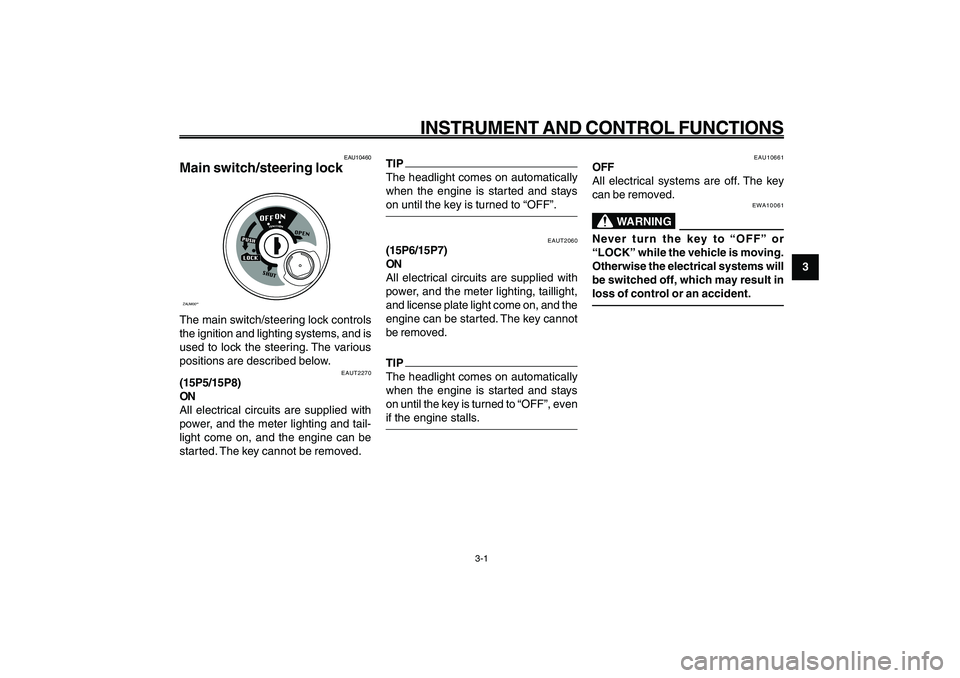
Main switch/steering lock
EAU10460
Main switch/steering lockZAUM00**The main switch/steering lock controls
the ignition and lighting systems, and is
used to lock the steering. The various
positions are described below.
EAUT2270
(15P5/15P8)
ON
All electrical circuits are supplied with
power, and the meter lighting and tail-
light come on, and the engine can be
started. The key cannot be removed.
EAUT2060
(15P6/15P7)
ON
All electrical circuits are supplied with
power, and the meter lighting, taillight,
and license plate light come on, and the
engine can be started. The key cannot
be removed.TIP
The headlight comes on automatically
when the engine is started and stays
on until the key is turned to “OFF”, even
if the engine stalls.
EAU10661
OFF
All electrical systems are off. The key
can be removed.
EWA10061
WARNING
Never turn the key to “OFF” or
“LOCK” while the vehicle is moving.
Otherwise the electrical systems will
be switched off, which may result in
loss of control or an accident.
EAU1044E
INSTRUMENT AND CONTROL FUNCTIONS
TIP
The headlight comes on automatically
when the engine is started and stays
on until the key is turned to “OFF”.
Page 19 of 74
3-19
1
2
3
4
5
6
7
8
9
EAU1044E
INSTRUMENT AND CONTROL FUNCTIONS
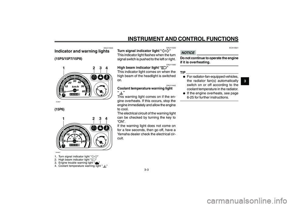
EAU11020
Turn signal indicator light “
5 55 5
5”
This indicator light flashes when the turn
signal switch is pushed to the left or right.
EAU11080
High beam indicator light “
& && &
&”
This indicator light comes on when the
high beam of the headlight is switched
on. Indicator and warning lights
Turn signal indicator light
High beam indicator light
Coolant temperature warning light
EAU11442
Coolant temperature warning light
“
”
This warning light comes on if the en-
gine overheats. If this occurs, stop the
engine immediately and allow the engine
to cool.
The electrical circuit of the warning light
can be checked by turning the key to
“ON”.
If the warning light does not come on
for a few seconds, then go off, have a
Yamaha dealer check the electrical cir-
cuit.
3-3
EAU11003
Indicator and warning lights(15P5/15P7/15P8)ZAUM00**
3
24
1
(15P6)ZAUM00**
0102030
40
50
60
3
24
1
1. Turn signal indicator light "5"
2. High beam indicator light "&"
3. Engine trouble warning light "
"
4. Coolant temperature warning light "
"
ECA10021
NOTICEDo not continue to operate the engine
if it is overheating.TIP●
For radiator-fan-equipped vehicles,
the radiator fan(s) automatically
switch on or off according to the
coolant temperature in the radiator.
●
If the engine overheats, see page
6-25 for further instructions.
Page 20 of 74
3-20
1
2
3
4
5
6
7
8
9
EAU1044E
INSTRUMENT AND CONTROL FUNCTIONS
3-4
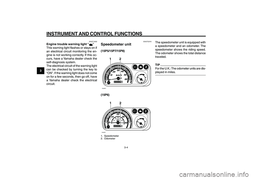
EAUT2310
Speedometer unit(15P5/15P7/15P8)ZAUM00**
2
1
(15P6)ZAUM00**
2
0102030
40
50
60
1
1. Speedometer
2. Odometer
Engine trouble warning light
Speedometer unit
The speedometer unit is equipped with
a speedometer and an odometer. The
speedometer shows the riding speed.
The odometer shows the total distance
traveled.
TIP
For the U.K.: The odometer units are dis-
played in miles.
EAUT1932
Engine trouble warning light “
”
This warning light flashes or stays on if
an electrical circuit monitoring the en-
gine is not working correctly. If this oc-
curs, have a Yamaha dealer check the
self-diagnosis system.
The electrical circuit of the warning light
can be checked by turning the key to
“ON”. If the warning light does not come
on for a few seconds, then go off, have
a Yamaha dealer check the electrical
circuit.
Page 23 of 74
3-23
1
2
3
4
5
6
7
8
9
EAU1044E
INSTRUMENT AND CONTROL FUNCTIONS
3-7
Brake lever, rear
Fuel tank cap
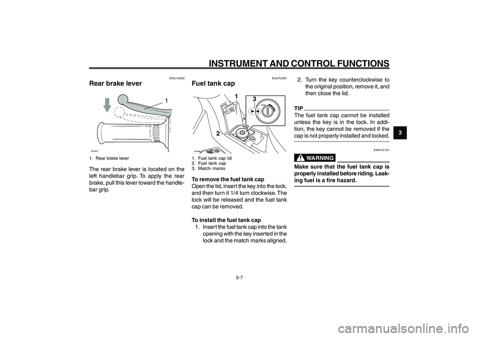
EAUT2281
Fuel tank capZAUM00**
3
1
2
1. Fuel tank cap lid
2. Fuel tank cap
3. Match marksTo remove the fuel tank cap
Open the lid, insert the key into the lock,
and then turn it 1/4 turn clockwise. The
lock will be released and the fuel tank
cap can be removed.
To install the fuel tank cap
1. Inser t the fuel tank cap into the tank
opening with the key inserted in the
lock and the match marks aligned.2. Turn the key counterclockwise to
the original position, remove it, and
then close the lid.
TIP
The fuel tank cap cannot be installed
unless the key is in the lock. In addi-
tion, the key cannot be removed if the
cap is not properly installed and locked.
EWA10131
WARNING
Make sure that the fuel tank cap is
properly installed before riding. Leak-
ing fuel is a fire hazard.
EAU12950
Rear brake lever
1
ZAUM00**1. Rear brake leverThe rear brake lever is located on the
left handlebar grip. To apply the rear
brake, pull this lever toward the handle-
bar grip.
Page 24 of 74
3-24
1
2
3
4
5
6
7
8
9
EAU1044E
INSTRUMENT AND CONTROL FUNCTIONS
3-8
smoking, or while in the vicinity of
sparks, open flames, or other
sources of ignition such as the pi-
lot lights of water heaters and
clothes dryers.
2. Do not overfill the fuel tank. Stop
filling when the fuel reaches the
bottom of the filler tube. Because
fuel expands when it heats up, heat
from the engine or the sun can
cause fuel to spill out of the fuel
tank.
3. Wipe up any spilled fuel immedi-
ately.
NOTICE:
Immediately wipe
off spilled fuel with a clean, dry,
soft cloth, since fuel may dete-
riorate painted surfaces or plas-
tic parts.
[ECA10071]
4. Be sure to securely close the fuel
tank cap.
EWA15151
WARNING
Gasoline is poisonous and can
cause injury or death. Handle gaso-
line with care. Never siphon gasoline
by mouth. If you should swallowsome gasoline or inhale a lot of gaso-
line vapor, or get some gasoline in
your eyes, see your doctor immedi-
ately. If gasoline spills on your skin,
wash with soap and water. If gaso-
line spills on your clothing, change
your clothes.
EAU33520
Recommended fuel:
REGULAR UNLEADED GASOLINE
ONLY
Fuel tank capacity:
4.5 L (1.19 US gal) (0.99 Imp.gal)
ECA11400
NOTICEUse only unleaded gasoline. The use
of leaded gasoline will cause severe
damage to internal engine parts, such
as the valves and piston rings, as well
as to the exhaust system.Your Yamaha engine has been designed
to use regular unleaded gasoline with a
research octane number of 91 or higher.
If knocking (or pinging) occurs, use a
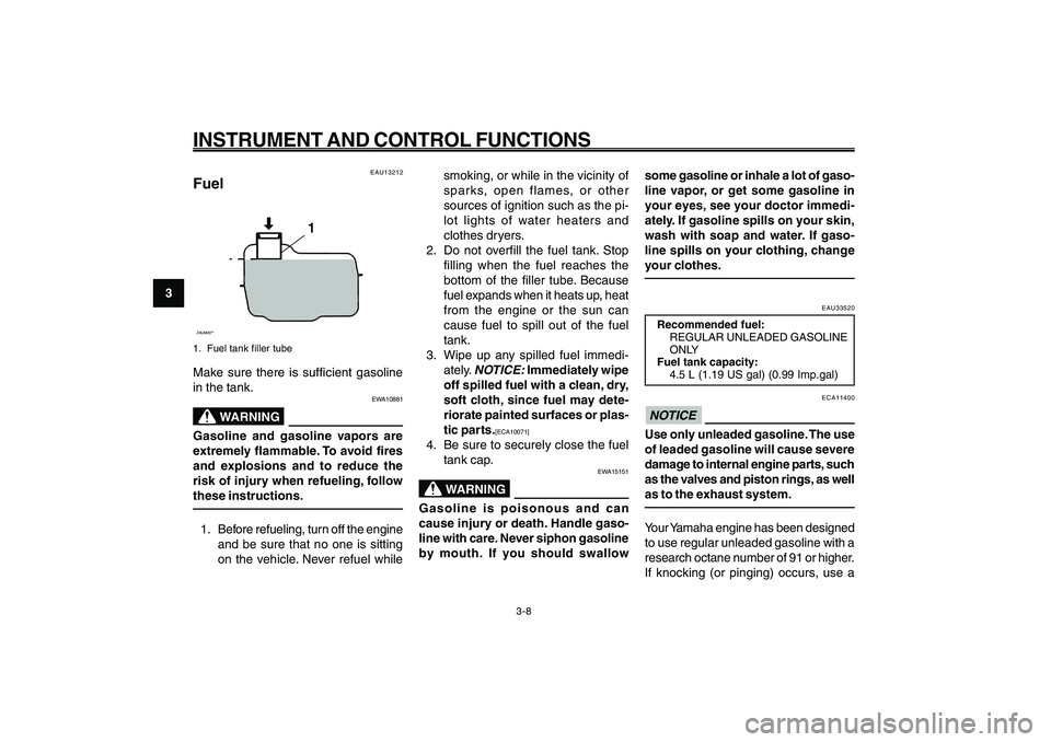
EAU13212
FuelZAUM00**
1
1. Fuel tank filler tubeMake sure there is sufficient gasoline
in the tank.
EWA10881
WARNING
Gasoline and gasoline vapors are
extremely flammable. To avoid fires
and explosions and to reduce the
risk of injury when refueling, follow
these instructions.1. Before refueling, turn off the engine
and be sure that no one is sitting
on the vehicle. Never refuel while Fuel
Page 25 of 74
3-25
1
2
3
4
5
6
7
8
9
EAU1044E
INSTRUMENT AND CONTROL FUNCTIONS
3-9
Catalytic converters
EAU13445
Catalytic convertersThis vehicle is equipped with catalytic
converters in the exhaust system.
EWA10862
WARNING
The exhaust system is hot after op-
eration. To prevent a fire hazard or
burns:● ●● ●
●
Do not park the vehicle near pos-
sible fire hazards such as grass
or other materials that easily
burn.
● ●● ●
●
Park the vehicle in a place where
pedestrians or children are not
likely to touch the hot exhaust
system.
● ●● ●
●
Make sure that the exhaust sys-
tem has cooled down before do-
ing any maintenance work.
● ●● ●
●
Do not allow the engine to idle
more than a few minutes. Long
idling can cause a build-up of
heat.
ECA10701
NOTICEUse only unleaded gasoline. The use
of leaded gasoline will cause
unrepairable damage to the catalytic
converter.
gasoline of a different brand or premium
unleaded fuel. Use of unleaded fuel will
extend spark plug life and reduce main-
tenance costs.