clock YAMAHA SR400 2016 Owners Manual
[x] Cancel search | Manufacturer: YAMAHA, Model Year: 2016, Model line: SR400, Model: YAMAHA SR400 2016Pages: 96, PDF Size: 2.52 MB
Page 22 of 96
Instrument and control functions
3-8
1
2
3
4
5
6
7
8
9
10
11
12
13
14
EAU13125
Fuel tank cap
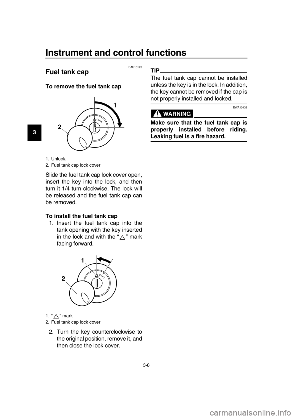
To remove the fuel tank cap
Slide the fuel tank cap lock cover open,
insert the key into the lock, and then
turn it 1/4 turn clockwise. The lock will
be released and the fuel tank cap can
be removed.
To install the fuel tank cap 1. Insert the fuel tank cap into the tank opening with the key inserted
in the lock and with the “ ” mark
facing forward.
2. Turn the key counterclockwise to the original position, remove it, and
then close the lock cover.
TIP
The fuel tank cap cannot be installed
unless the key is in the lock. In addition,
the key cannot be removed if the cap is
not properly installed and locked.
WARNING
EWA10132
Make sure that the fuel tank cap is
properly installed before riding.
Leaking fuel is a fire hazard.
1. Unlock.
2. Fuel tank cap lock cover
1. “ ” mark
2. Fuel tank cap lock cover
2
1
1
2
2RD-28199-E1.book 8 ページ 2015年9月3日 木曜日 午後3時42分
Page 40 of 96
Periodic maintenance and adjustment
6-2
1
2
3
4
5
6
7
8
9
10
11
12
13
14
EAU17303
Emission controls not only function to
ensure cleaner air, but are also vital to
proper engine operation and maximum
performance. In the following periodic
maintenance charts, the services relat-
ed to emissions control are grouped
separately. These services require
specialized data, knowledge, and
equipment. Maintenance, replacement,
or repair of the emission control devic-
es and systems may be performed by
any repair establishment or individual
that is certified (if applicable). Yamaha
dealers are trained and equipped to
perform these particular services.
EAU59370
Owner’s tool kit
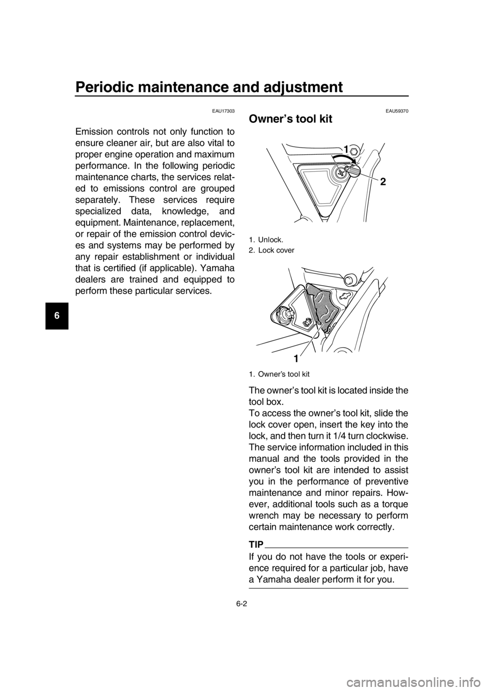
The owner’s tool kit is located inside the
tool box.
To access the owner’s tool kit, slide the
lock cover open, insert the key into the
lock, and then turn it 1/4 turn clockwise.
The service information included in this
manual and the tools provided in the
owner’s tool kit are intended to assist
you in the performance of preventive
maintenance and minor repairs. How-
ever, additional tools such as a torque
wrench may be necessary to perform
certain maintenance work correctly.
TIP
If you do not have the tools or experi-
ence required for a particular job, have
a Yamaha dealer perform it for you.
1. Unlock.
2. Lock cover
1. Owner’s tool kit
1 2
1
2RD-28199-E1.book 2 ページ 2015年9月3日 木曜日 午後3時42分
Page 74 of 96
Periodic maintenance and adjustment
6-36
1
2
3
4
5
6
7
8
9
10
11
12
13
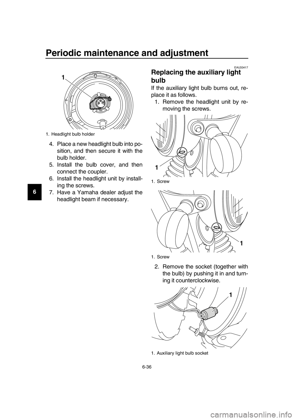
14 4. Place a new headlight bulb into po-
sition, and then secure it with the
bulb holder.
5. Install the bulb cover, and then connect the coupler.
6. Install the headlight unit by install- ing the screws.
7. Have a Yamaha dealer adjust the headlight beam if necessary.
EAU33417
Replacing the auxiliary light
bulb
If the auxiliary light bulb burns out, re-
place it as follows.1. Remove the headlight unit by re- moving the screws.
2. Remove the socket (together with the bulb) by pushing it in and turn-
ing it counterclockwise.
1. Headlight bulb holder
1
1. Screw
1. Screw
1. Auxiliary light bulb socket
1
1
1
2RD-28199-E1.book 36 ページ 2015年9月3日 木曜日 午後3時42分
Page 75 of 96
Periodic maintenance and adjustment
6-37
1
2
3
4
5
6
7
8
9
10
11
12
13
14
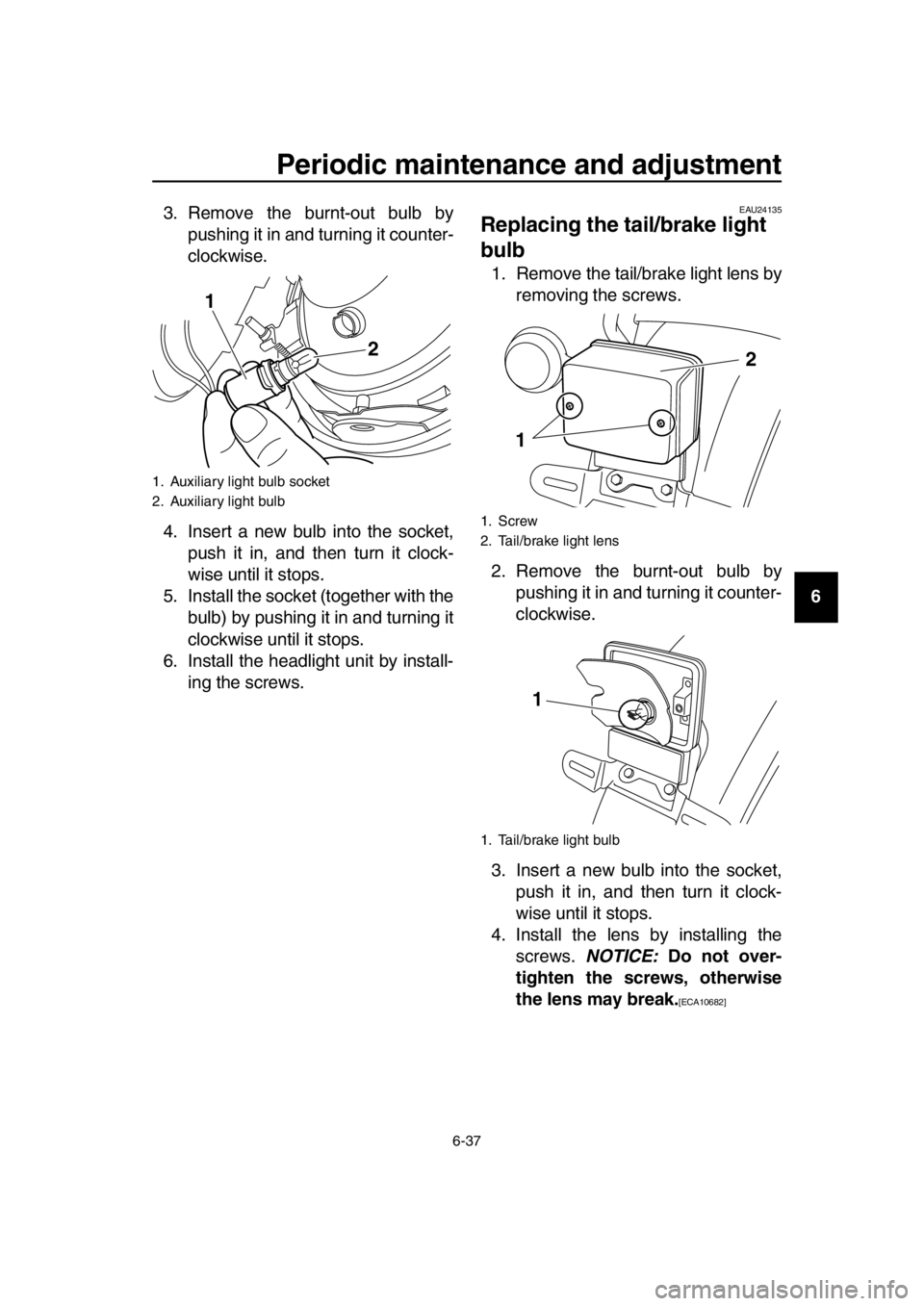
3. Remove the burnt-out bulb by
pushing it in and turning it counter-
clockwise.
4. Insert a new bulb into the socket, push it in, and then turn it clock-
wise until it stops.
5. Install the socket (together with the bulb) by pushing it in and turning it
clockwise until it stops.
6. Install the headlight unit by install- ing the screws.
EAU24135
Replacing the tail/brake light
bulb
1. Remove the tail/brake light lens byremoving the screws.
2. Remove the burnt-out bulb by pushing it in and turning it counter-
clockwise.
3. Insert a new bulb into the socket, push it in, and then turn it clock-
wise until it stops.
4. Install the lens by installing the screws. NOTICE: Do not over-
tighten the screws, otherwise
the lens may break.
[ECA10682]
1. Auxiliary light bulb socket
2. Auxiliary light bulb
1
2
1. Screw
2. Tail/brake light lens
1. Tail/brake light bulb
1 2
1
2RD-28199-E1.book 37 ページ 2015年9月3日 木曜日 午後3時42分
Page 76 of 96
Periodic maintenance and adjustment
6-38
1
2
3
4
5
6
7
8
9
10
11
12
13
14
EAU60010
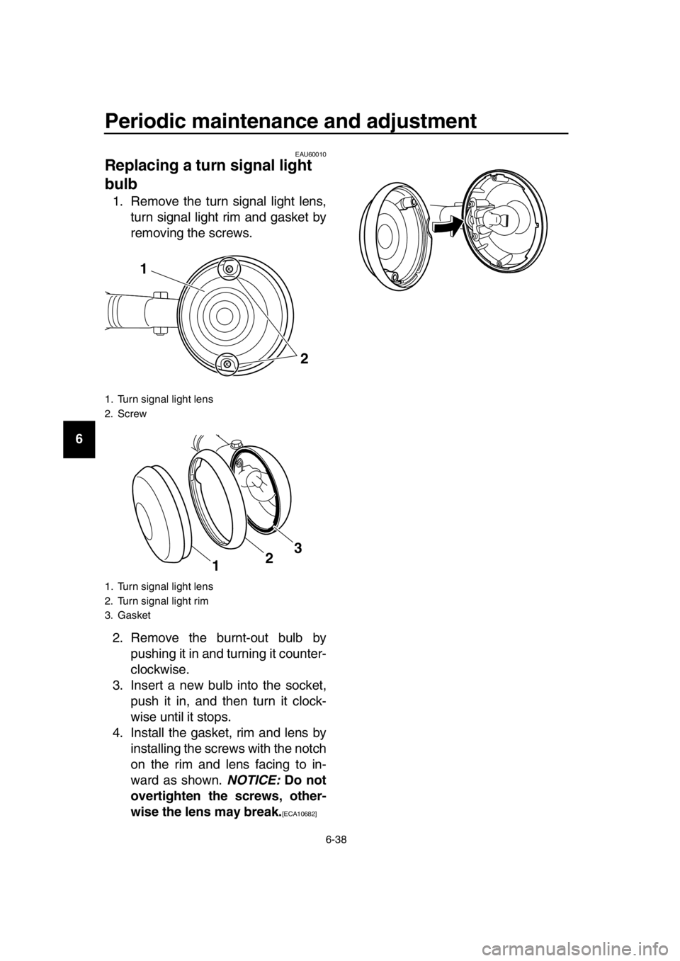
Replacing a turn signal light
bulb
1. Remove the turn signal light lens, turn signal light rim and gasket by
removing the screws.
2. Remove the burnt-out bulb by pushing it in and turning it counter-
clockwise.
3. Insert a new bulb into the socket, push it in, and then turn it clock-
wise until it stops.
4. Install the gasket, rim and lens by installing the screws with the notch
on the rim and lens facing to in-
ward as shown. NOTICE: Do not
overtighten the screws, other-
wise the lens may break.
[ECA10682]
1. Turn signal light lens
2. Screw
1. Turn signal light lens
2. Turn signal light rim
3. Gasket
1
2
3
2
1
2RD-28199-E1.book 38 ページ 2015年9月3日 木曜日 午後3時42分