YAMAHA TDR 125 2000 Repair Manual
Manufacturer: YAMAHA, Model Year: 2000, Model line: TDR 125, Model: YAMAHA TDR 125 2000Pages: 104, PDF Size: 4.88 MB
Page 61 of 104
6-16
PERIODIC MAINTENANCE AND MINOR REPAIR
1
2
3
4
5
6
7
8
9
NOTE:
If the specified idle speed cannot be
obtained by performing the above
adjustment, consult a Yamaha deal-
er.
Standard idle speed:
1,300 ~ 1,500 r/min
1,400 ~ 1,500 r/min
(A, CH only)
EAU00634
Throttle cable free play
adjustment
NOTE:
Before checking the throttle cable
free play, the engine idling speed
should be adjusted.
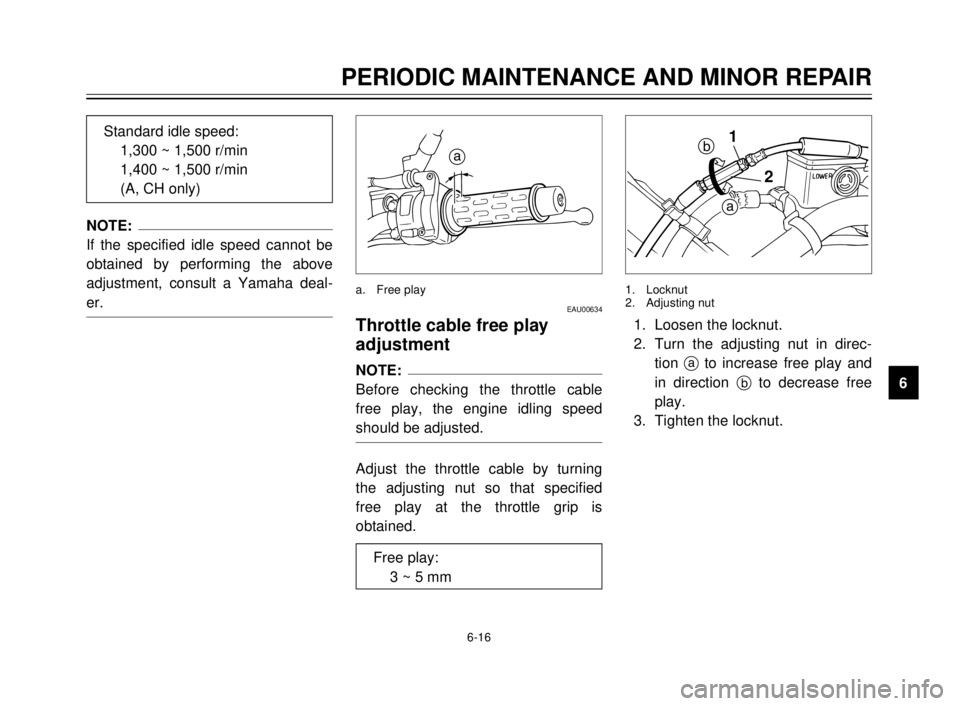
Adjust the throttle cable by turning
the adjusting nut so that specified
free play at the throttle grip is
obtained.
a. Free play
a
Free play:
3 ~ 5 mm
2 1
b
a
1. Loosen the locknut.
2. Turn the adjusting nut in direc-
tion ato increase free play and
in direction bto decrease free
play.
3. Tighten the locknut.
1. Locknut
2. Adjusting nut
5AE-9-E3 (ENG) 4/11/0 11:06 AM Page 59
Page 62 of 104

6-17
PERIODIC MAINTENANCE AND MINOR REPAIR
1
2
3
4
5
6
7
8
9
EAU00647Tires
To ensure maximum performance,
long service, and safe operation, note
the following:
Tire air pressure
Always check and adjust the tire
pressure before operating the motor-
cycle.
EW000082
w
Tire inflation pressure should be
checked and adjusted when the
temperature of the tire equals the
ambient air temperature. Tire infla-
tion pressure must be adjusted
according to total weight of cargo,
rider, passenger, and accessories
(fairing, saddlebags, etc. if
approved for this model), and vehi-
cle speed.
* Load is the total weight of cargo, rider, passenger
and accessories. Maximum load*180 kg
179 kg (CH, A)
Cold tire pressure Front Rear
175 kPa 200 kPa
Up to 90 kg load* (1.75 kg/cm
2, (2.00 kg/cm2,1.75 bar) 2.00 bar)
90 kg load ~175 kPa 225 kPa
Maximum load*(1.75 kg/cm
2, (2.25 kg/cm2,
1.75 bar) 2.25 bar)
EW000083
w
Proper loading of your motorcycle
is important for several character-
istics of your motorcycle, such as
handling, braking, performance
and safety. Do not carry loosely
packed items that can shift.
Securely pack your heaviest items
close to the center of the motorcy-
cle, and distribute the weight even-
ly from side to side. Properly
adjust the suspension for your
load, and check the condition and
pressure of your tires. NEVER
OVERLOAD YOUR MOTORCYCLE.
Make sure the total weight of the
cargo, rider, passenger, and
accessories (fairing, saddlebags,
etc. if approved for this model)
does not exceed the maximum
load of the motorcycle. Operation
of an overloaded motorcycle could
cause tire damage, an accident, or
even injury.
5AE-9-E3 (ENG) 4/11/0 11:06 AM Page 60
Page 63 of 104
6-18
PERIODIC MAINTENANCE AND MINOR REPAIR
1
2
3
4
5
6
7
8
9 Tire inspection
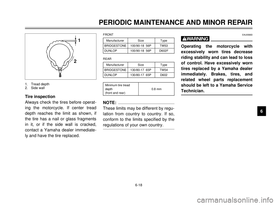
Always check the tires before operat-
ing the motorcycle. If center tread
depth reaches the limit as shown, if
the tire has a nail or glass fragments
in it, or if the side wall is cracked,
contact a Yamaha dealer immediate-
ly and have the tire replaced.
1
2
1. Tread depth
2. Side wall
NOTE:
These limits may be different by regu-
lation from country to country. If so,
conform to the limits specified by the
regulations of your own country.
Manufacturer Size Type
BRIDGESTONE 100/90-18 56P TW53
DUNLOP 100/90-18 56P D602F
FRONT
Manufacturer Size Type
BRIDGESTONE 130/80-17 65P TW54
DUNLOP 130/80-17 65P D602
REAR
Minimum tire tread
depth 0.8 mm
(front and rear)
EAU00683
w
Operating the motorcycle with
excessively worn tires decrease
riding stability and can lead to loss
of control. Have excessively worn
tires replaced by a Yamaha dealer
immediately. Brakes, tires, and
related wheel parts replacement
should be left to a Yamaha Service
Technician.
5AE-9-E3 (ENG) 4/11/0 11:06 AM Page 61
Page 64 of 104
6-19
PERIODIC MAINTENANCE AND MINOR REPAIR
1
2
3
4
5
6
7
8
9
EAU00687Wheels
To ensure maximum performance,
long service, and safe operation, note
the following:
8Always inspect the wheels
before a ride. Check for cracks,
bends, or warpage of the wheels.
If any abnormal condition exists
in a wheel, consult a Yamaha
dealer. Do not attempt even
small repairs to the wheel. If a
wheel is deformed or cracked, it
must be replaced.
8Tires and wheels should be bal-
anced whenever either one is
changed or replaced. Failure to
have a wheel balanced can
result in poor performance,
adverse handling characteristics,
and shortened tire life.
8Ride at moderate speeds after
changing a tire since the tire sur-
face must first be broken in for it
to develop its optimal character-
istics.
a
b12 3
EAU00694
Clutch lever free play
adjustment
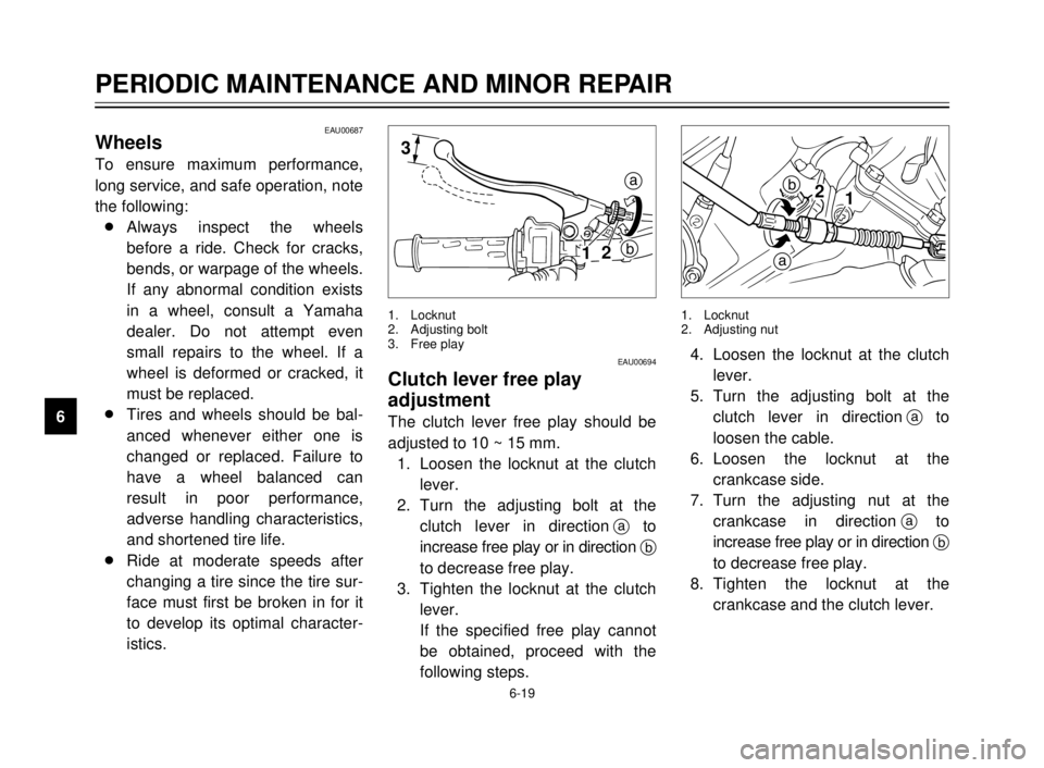
The clutch lever free play should be
adjusted to 10 ~ 15 mm.
1. Loosen the locknut at the clutch
lever.
2. Turn the adjusting bolt at the
clutch lever in directionato
increase free play or in direction b
to decrease free play.
3. Tighten the locknut at the clutch
lever.
If the specified free play cannot
be obtained, proceed with the
following steps.
1. Locknut
2. Adjusting bolt
3. Free play
b
a
12
4. Loosen the locknut at the clutch
lever.
5. Turn the adjusting bolt at the
clutch lever in directionato
loosen the cable.
6. Loosen the locknut at the
crankcase side.
7. Turn the adjusting nut at the
crankcase in directionato
increase free play or in direction b
to decrease free play.
8. Tighten the locknut at the
crankcase and the clutch lever.
1. Locknut
2. Adjusting nut
5AE-9-E3 (ENG) 4/11/0 11:06 AM Page 62
Page 65 of 104
6-20
PERIODIC MAINTENANCE AND MINOR REPAIR
1
2
3
4
5
6
7
8
9
1
2
b
a3
EAU00696
Front brake lever free play
adjustment
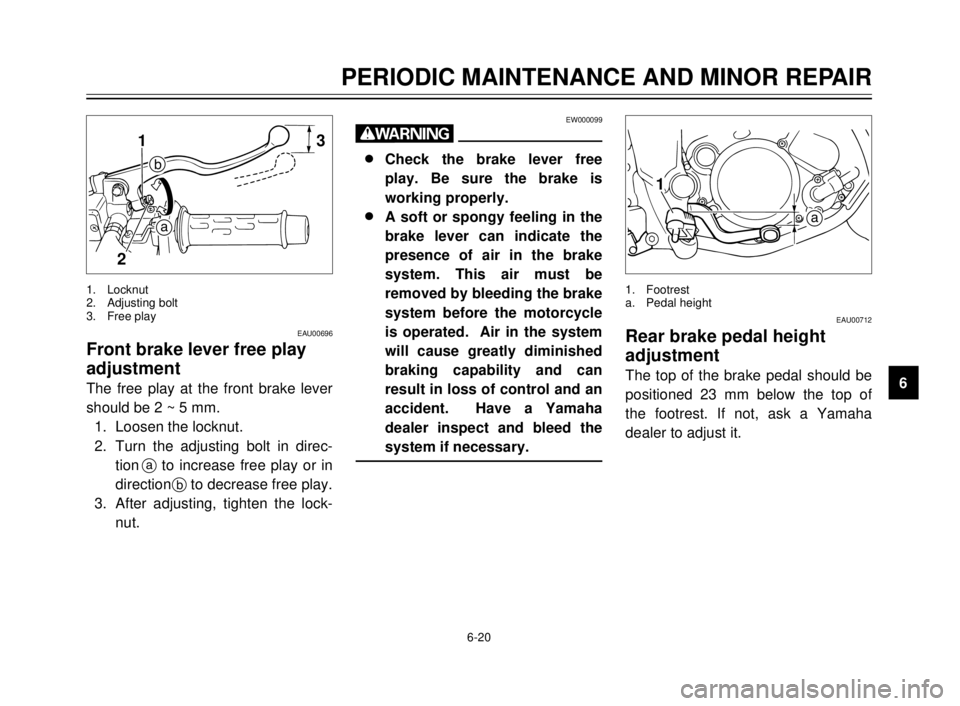
The free play at the front brake lever
should be 2 ~ 5 mm.
1. Loosen the locknut.
2. Turn the adjusting bolt in direc-
tionato increase free play or in
directionbto decrease free play.
3. After adjusting, tighten the lock-
nut.
1. Locknut
2. Adjusting bolt
3. Free play
EW000099
w
8 8
Check the brake lever free
play. Be sure the brake is
working properly.
8 8
A soft or spongy feeling in the
brake lever can indicate the
presence of air in the brake
system. This air must be
removed by bleeding the brake
system before the motorcycle
is operated. Air in the system
will cause greatly diminished
braking capability and can
result in loss of control and an
accident. Have a Yamaha
dealer inspect and bleed the
system if necessary.
a
1
EAU00712
Rear brake pedal height
adjustment
The top of the brake pedal should be
positioned 23 mm below the top of
the footrest. If not, ask a Yamaha
dealer to adjust it.
1. Footrest
a. Pedal height
5AE-9-E3 (ENG) 4/11/0 11:06 AM Page 63
Page 66 of 104
6-21
PERIODIC MAINTENANCE AND MINOR REPAIR
1
2
3
4
5
6
7
8
9
EW000109
w
A soft or spongy feeling in the
brake pedal can indicate the pres-
ence of air in the brake system.
This air must be removed by
bleeding the brake system before
the motorcycle is operated. Air in
the system will cause greatly
diminished braking capability and
can result in loss of control and an
accident. Have a Yamaha dealer
inspect and bleed the system if
necessary.
EAU00713
Brake light switch
adjustment
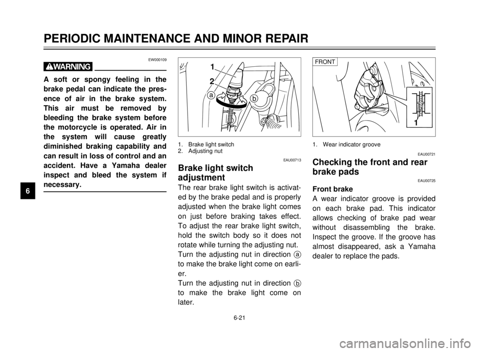
The rear brake light switch is activat-
ed by the brake pedal and is properly
adjusted when the brake light comes
on just before braking takes effect.
To adjust the rear brake light switch,
hold the switch body so it does not
rotate while turning the adjusting nut.
Turn the adjusting nut in direction a
to make the brake light come on earli-
er.
Turn the adjusting nut in direction b
to make the brake light come on
later.
ba
1
2
1. Brake light switch
2. Adjusting nut
EAU00721
Checking the front and rear
brake pads
EAU00725
Front brake
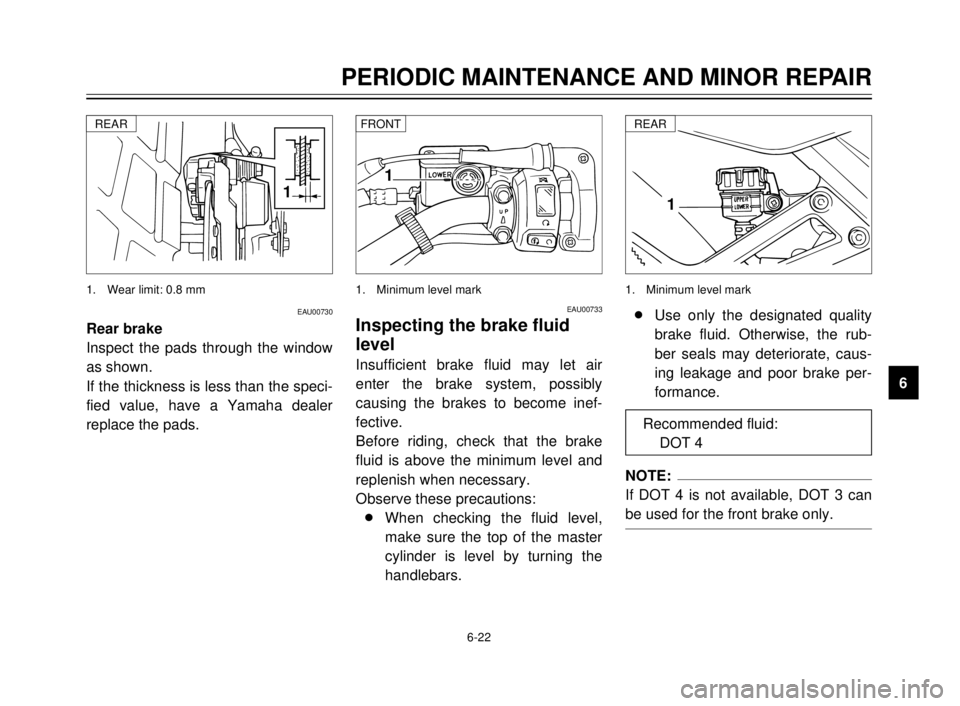
A wear indicator groove is provided
on each brake pad. This indicator
allows checking of brake pad wear
without disassembling the brake.
Inspect the groove. If the groove has
almost disappeared, ask a Yamaha
dealer to replace the pads.
1
1. Wear indicator grooveFRONT
5AE-9-E3 (ENG) 4/11/0 11:06 AM Page 64
Page 67 of 104
6-22
PERIODIC MAINTENANCE AND MINOR REPAIR
1
2
3
4
5
6
7
8
9
1
1. Wear limit: 0.8 mmREAR
EAU00733
Inspecting the brake fluid
level
Insufficient brake fluid may let air
enter the brake system, possibly
causing the brakes to become inef-
fective.
Before riding, check that the brake
fluid is above the minimum level and
replenish when necessary.
Observe these precautions:
8When checking the fluid level,
make sure the top of the master
cylinder is level by turning the
handlebars.
1
1. Minimum level markFRONT
1
1. Minimum level mark
8Use only the designated quality
brake fluid. Otherwise, the rub-
ber seals may deteriorate, caus-
ing leakage and poor brake per-
formance.
NOTE:
If DOT 4 is not available, DOT 3 can
be used for the front brake only.
REAR
Recommended fluid:
DOT 4
EAU00730
Rear brake
Inspect the pads through the window
as shown.
If the thickness is less than the speci-
fied value, have a Yamaha dealer
replace the pads.
5AE-9-E3 (ENG) 4/11/0 11:06 AM Page 65
Page 68 of 104
6-23
PERIODIC MAINTENANCE AND MINOR REPAIR
1
2
3
4
5
6
7
8
98Refill with the same type of brake
fluid. Mixing fluids may result in a
harmful chemical reaction and
lead to poor brake performance.
8Be careful that water does not
enter the master cylinder when
refilling. Water will significantly
lower the boiling point of the fluid
and may result in vapor lock.
8Brake fluid may deteriorate paint-
ed surfaces or plastic parts.
Always clean up spilled fluid
immediately.
8Have a Yamaha dealer check
the cause if the brake fluid level
goes down.
EAU00742Brake fluid replacement
The brake fluid should be replaced
only by trained Yamaha service per-
sonnel. Have the Yamaha dealer
replace the following components
during periodic maintenance or when
they are damaged or leaking:
8oil seals (every two years)
8brake hoses (every four years)
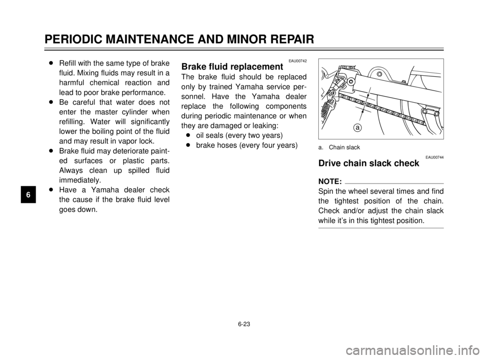
EAU00744Drive chain slack check
NOTE:
Spin the wheel several times and find
the tightest position of the chain.
Check and/or adjust the chain slack
while it’s in this tightest position.
a
a. Chain slack
5AE-9-E3 (ENG) 4/11/0 11:06 AM Page 66
Page 69 of 104
6-24
PERIODIC MAINTENANCE AND MINOR REPAIR
1
2
3
4
5
6
7
8
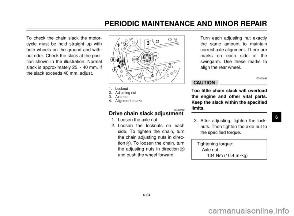
9 To check the chain slack the motor-
cycle must be held straight up with
both wheels on the ground and with-
out rider. Check the slack at the posi-
tion shown in the illustration. Normal
slack is approximately 25 ~ 40 mm. If
the slack exceeds 40 mm, adjust.
EAU00762Drive chain slack adjustment
1. Loosen the axle nut.
2. Loosen the locknuts on each
side. To tighten the chain, turn
the chain adjusting nuts in direc-
tiona. To loosen the chain, turn
the adjusting nuts in directionb
and push the wheel forward.
3
412
a
b
1. Locknut
2. Adjusting nut
3. Axle nut
4. Alignment marks
Turn each adjusting nut exactly
the same amount to maintain
correct axle alignment. There are
marks on each side of the
swingarm. Use these marks to
align the rear wheel.
EC000096
cC
Too little chain slack will overload
the engine and other vital parts.
Keep the slack within the specified
limits.
3. After adjusting, tighten the lock-
nuts. Then tighten the axle nut to
the specified torque.
Tightening torque:
Axle nut:
104 Nm (10.4 m0kg)
5AE-9-E3 (ENG) 4/11/0 11:06 AM Page 67
Page 70 of 104
6-25
PERIODIC MAINTENANCE AND MINOR REPAIR
1
2
3
4
5
6
7
8
9
EAU03006
Drive chain lubrication
The chain consists of many parts
which work with each other. If the
chain is not maintained properly, it
will wear out quickly. Therefore, the
chain must be serviced regularly.
This service is especially necessary
when riding in dusty areas. This
motorcycle is equipped with a sealed
type chain. Steam cleaning, high-
pressure washers, and solvents can
damage the drive chain, so do not
use these for cleaning it. Use only
kerosene to clean the drive chain.
Wipe it dry, and thoroughly lubricate it
with SAE 30 ~ 50W motor oil. Do not
use any other lubricants on the drive
chain. They may contain solvents
that could damage the sealed chain.
EC000097
cC
Be sure to oil the chain after wash-
ing the motorcycle or riding in the
rain.
EAU02962
Cable inspection and
lubrication
EW000112
w
Damage to the outer housing of
cables may lead to internal rusting
and interfere with the cable move-
ment. Replace damaged cables as
soon as possible to prevent unsafe
conditions.
Lubricate the cables and cable ends.
If a cable does not operate smoothly,
ask a Yamaha dealer to replace it.
Recommended lubricant:
Engine oil
EAU00773
Throttle cable and grip
lubrication
The throttle twist grip assembly
should be greased at the time that
the cable is lubricated, since the grip
must be removed to get at the end of
the throttle cable. After removing the
screws, hold the end of the cable up
in the air and put in several drops of
lubricant. With the throttle grip disas-
sembled, coat the metal surface of
the grip assembly with a suitable all-
purpose grease.
5AE-9-E3 (ENG) 4/11/0 11:06 AM Page 68